Endress+Hauser iTEMP TMT162 Operating Instructions Manual
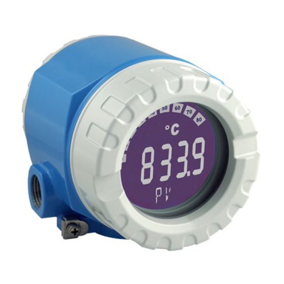
Temperature field transmitter
Hide thumbs
Also See for iTEMP TMT162:
- Operating instructions manual (160 pages) ,
- Brief operating instructions (52 pages) ,
- Technical information (25 pages)

Related Manuals for Endress+Hauser iTEMP TMT162


Summary of Contents for Endress+Hauser iTEMP TMT162
-
Page 1: Operating Instructions
Products Solutions Services BA01801T/09/EN/01.17 71380552 Valid as of version 04.01 (device version) Operating Instructions iTEMP TMT162 Temperature field transmitter... -
Page 3: Table Of Contents
Requirements for the personnel ... . 7 10.1 Endress+Hauser services ....40 Designated use ...... -
Page 4: Important Document Information
Important document information iTEMP TMT162 Important document information Function of document and how to use 1.1.1 Document function These Operating Instructions contain all the information that is required in various phases of the life cycle of the device: from product identification, incoming acceptance and storage, to mounting, connection, operation and commissioning through to troubleshooting, maintenance and disposal. - Page 5 TMT162 Important document information Symbol Meaning Ground connection A grounded terminal which, as far as the operator is concerned, is grounded via a grounding system. Protective ground connection A terminal which must be connected to ground prior to establishing any other connections.
-
Page 6: Documentation
This manual applies in addition to the Operating Instructions, Technical Information and ATEX Safety Instructions. The requirements specific for the protection function are described in this Safety Manual. The document types listed are available: In the Download Area of the Endress+Hauser Internet site: www.endress.com → Downloads Registered trademarks HART®... -
Page 7: Basic Safety Instructions
Conversions to the device Unauthorized modifications to the device are not permitted and can lead to unforeseeable dangers. ‣ If, despite this, modifications are required, consult with Endress+Hauser. Repair To ensure continued operational safety and reliability: ‣ Carry out repairs on the device only if they are expressly permitted. -
Page 8: Product Safety
It meets general safety standards and legal requirements. It also complies with the EC directives listed in the device-specific EC Declaration of Conformity. Endress+Hauser confirms this by affixing the CE mark to the device. -
Page 9: Identification
TMT162 Incoming acceptance and product identification Incoming acceptance and product identification Incoming acceptance A0024856 Unpack the temperature transmitter carefully. Is the packaging or content damaged? Damaged components may not be installed as the manufacturer can otherwise not guarantee compliance with the original safety requirements or the material resistance, and can therefore not be held responsible for any resulting damage. -
Page 10: Scope Of Delivery
Incoming acceptance and product identification iTEMP TMT162 3.2.1 Nameplate Is this the correct device? Check the data on the nameplate of the device and compare them against the requirements of the measuring point: Order code, serial number and TAG of device Power supply, degree of protection, etc. -
Page 11: Transport And Storage
TMT162 Incoming acceptance and product identification HART® protocol certification The temperature transmitter is registered by the HART® FieldComm Group. The device meets the requirements of the HART Communication Protocol Specifications, Revision 7 (HCF 7.6). Transport and storage Carefully remove all the packaging material and protective covers that are part of the transported package. -
Page 12: Installation
Installation iTEMP TMT162 Installation If stable sensors are used, the device can be fitted directly to the sensor. For remote mounting to a wall or stand pipe, two mounting brackets are available. The illuminated display can be mounted in four different positions. - Page 13 TMT162 Installation 6. Guide the fieldbus cables (5) through the cable gland of the fieldbus transmitter housing into the connection compartment. 7. Screw the cable gland tight as described in the Ensuring the degree of protection section→ 20. The cable gland must meet explosion protection requirements.
-
Page 14: Display Mounting
Installation iTEMP TMT162 Display mounting Pro of- OF F Tes t 90° WR ITE LOC K 90° 90° 90° 3 mm A0025417 4 4 display installation positions, attachable in 90° stages Cover clamp Housing cover with O-ring Display with fitting kit and twist protection Electronics module 1. -
Page 15: Wiring
TMT162 Wiring Wiring Connection conditions CAUTION The electronics could be destroyed ‣ Switch off power supply before installing or connecting the device. Failure to observe this may result in destruction of parts of the electronics. ‣ When connecting Ex-certified devices, please take special note of the instructions and connection schematics in the Ex-specific supplement to these Operating Instructions. - Page 16 Wiring iTEMP TMT162 Terminal assignment Sensor 1 Bus connection and supply voltage Sensor 1 2-wire 3-wire 4-wire Sensor 2 A0024515-EN 5 Wiring the field transmitter NOTICE When connecting 2 sensors ensure that there is no galvanic connection between the sensors (e.g.
-
Page 17: Connecting The Measuring Device
TMT162 Wiring Connecting the measuring device 5.3.1 Cable glands or entries CAUTION Risk of damage ‣ Switch off power supply before installing or connecting the device. Failure to observe this may result in destruction of parts of the electronics. - Page 18 HELP SEND HOME Commubox A0033548 7 HART® connection with Endress+Hauser power supply unit, including integrated communication resistor Temperature field transmitter HART® handheld communicator PLC/DCS Configuration software, e.g. FieldCare Configuration via Field Xpert SFX350/370 Power supply unit, e.g. RN221 from Endress+Hauser ³...
-
Page 19: Special Connection Instructions
TMT162 Wiring A0010984 9 Shielding and grounding the signal cable at one end with HART® communication Supply unit Grounding point for HART® communication cable shield Grounding of the cable shield at one end Optional grounding of the field device, isolated from cable shielding... -
Page 20: Ensuring The Degree Of Protection
Wiring iTEMP TMT162 3 mm A0033829 11 Surge arrester function test Ohmmeter in high-impedance range = surge arrester working Ohmmeter in low-impedance range = surge arrester defective . Notify Endress +Hauser Service. Dispose of the defective surge arrester module as electronic waste. -
Page 21: Post-Connection Check
TMT162 Wiring Post-connection check Device condition and specifications Notes Is the device or cable undamaged (visual inspection)? Electrical connection Notes Does the supply voltage match the specifications on Standard mode and SIL mode: U = 11.5 to 42 V... -
Page 22: Operating Options
Hardware settings via DIP switch and proof-test button HART® handheld communicator PLC/DCS Configuration software, e.g. FieldCare Commubox: Power supply and modem for field devices with HART® protocol Configuration via Field Xpert SFX350/370 Power supply unit and active barrier, .e.g. RN221 from Endress+Hauser Endress+Hauser... - Page 23 TMT162 Operating options 6.1.1 Display and operating elements Display elements °F °C A0034101 14 LC display of the field transmitter (backlit, attachable in 90° stages) Item No. Function Description Bar graph display In increments of 10% with indicators for underranging and overranging.
- Page 24 Operating options iTEMP TMT162 Pro of- OF F Tes t WR ITE LOC K 3 mm A0033847 Procedure for setting the DIP switch or activating the proof test: 1. Remove the cover clamp. 2. Unscrew the housing cover together with the O-ring.
-
Page 25: Menu
TMT162 Operating options Structure and function of the operating menu 6.2.1 Structure of the operating menu Operating menu for operators and maintenances Setup Device tag Unit Sensor type Lower range value Upper range value Advanced setup Enter access code... - Page 26 Operating options iTEMP TMT162 The configuration in the SIL mode is different from the configuration in the standard mode. For more detailed information please refer to the Functional Safety Manual (SD01632T/09). Submenus and user roles Certain parts of the menu are assigned to certain user roles. Each user role corresponds to typical tasks within the lifecycle of the device.
-
Page 27: Operating Tool
6.3.2 DeviceCare Function range The fastest way to configure Endress+Hauser field devices is with the dedicated DeviceCare tool. DeviceCare' s user-friendly design enables transparent and intuitive device connection and configuration. Intuitive menus and step-by-step instructions with status information ensure optimum transparency. - Page 28 Operating options iTEMP TMT162 Source for device description files See data → 29 6.3.3 Field Xpert Function range Field Xpert is an industrial PDA with integrated touchscreen for commissioning and maintaining field devices in explosion hazardous and safe areas. It enables the efficient configuration of FOUNDATION fieldbus, HART and WirelessHART devices.
-
Page 29: System Integration
Sources for obtaining device descriptions (DD) or device type managers (DTM) FieldCare • www.endress.com → Download Area → Software (Endress+Hauser) • CD-ROM (contact Endress+Hauser) • DVD (contact Endress+Hauser) DeviceCare www.endress.com → Download Area → Software (Endress+Hauser) AMS Device Manager Please ask the operating tool manufacturer for information on where to (Emerson Process Management) obtain the DD/DTM. -
Page 30: Device Variables And Measured Values
System integration iTEMP TMT162 Device variables and measured values The following measured values are assigned to the individual device variables: Device variable code Measured value Sensor 1 Sensor 2 Device temperature Average of sensor 1 and sensor 2 Difference between sensor 1 and sensor 2... - Page 31 TMT162 System integration Command No. Designation 12, Cmd012 Read message 13, Cmd013 Read TAG, descriptor, date 14, Cmd014 Read primary variable transducer information 15, Cmd015 Read device information 16, Cmd016 Read final assembly number 17, Cmd017 Write message 18, Cmd018...
- Page 32 System integration iTEMP TMT162 Command No. Designation 523, Cmd523 Read condensed status mapping array 524, Cmd524 Write condensed status mapping 525, Cmd525 Reset condensed status map 526, Cmd526 Write status simulation mode 527, Cmd527 Simulate status bit Endress+Hauser...
-
Page 33: Commissioning
TMT162 Commissioning Commissioning Post-installation check Before commissioning the measuring point make sure that all final checks have been carried out: • "Post-installation check" checklist, → 12 • "Post-connection check” checklist, → 15 Switching on the transmitter Once the final checks have been successfully completed, it is time to switch on the supply voltage. -
Page 34: Diagnostics And Troubleshooting
In the event of a serious fault, a device might have to be returned to the manufacturer for repair. Refer to the "Return" section before returning the device to Endress+Hauser. → 43 Check display (local display) Display is blank - no connection to 1. - Page 35 TMT162 Diagnostics and troubleshooting Application errors without status messages for RTD sensor connection Problem Possible cause Solution Device programming is incorrect Change the Connection type device (number of wires). function. Device programming is incorrect Change scaling. (scaling). Incorrect RTD configured.
-
Page 36: Diagnostic Events
Diagnostics and troubleshooting iTEMP TMT162 Diagnostic events 9.2.1 Displaying diagnostic events NOTICE Status signals and diagnostic behavior can be configured manually for certain diagnostic events. If a diagnostic event occurs, however, it is not guaranteed that the measured values are valid for the event and comply with the process for the status signals S and M and the diagnostic behavior: 'Warning' and Disabled'. - Page 37 TMT162 Diagnostics and troubleshooting Diagnostic event and event text The fault can be identified by means of the diagnostic event. The event text helps you by providing information on the fault. Diagnostic event Status signal Event number Event text ↓...
- Page 38 Diagnostics and troubleshooting iTEMP TMT162 Diagnosti Customizable Customizable Status Diagnostic signal Short text Corrective measure behavior number from the from the factory factory customizable customizable Diagnostics for the sensor Device failure - sensor n 1. Restart device Alarm (sensor RJ) 2.
- Page 39 TMT162 Diagnostics and troubleshooting Diagnosti Customizable Customizable Status Diagnostic signal Short text Corrective measure behavior number from the from the factory factory customizable customizable Data transfer failed 1. Check connection. Alarm 2. Retry data transfer. Up-/download active Up-/download active, please wait.
-
Page 40: Compatibility
No special maintenance work is required for the temperature transmitter. 10.1 Endress+Hauser services Endress+Hauser offers a wide variety of services for maintenance such as recalibration, maintenance service or device tests. Your Endress+Hauser Sales Center can provide detailed information on the services. -
Page 41: Repair
TMT162 Repair Repair 11.1 General notes Repairs that are not described in these Operating Instructions must only be carried out directly by the manufacturer or by the service department. 11.2 Spare parts Spare parts currently available for the product can be found online at: http://www.products.endress.com/spareparts_consumables. - Page 42 Repair iTEMP TMT162 Item No. 1 Housing Cable entry: 2 x thread NPT ½" + terminal block + 1 dummy plug 2 x thread M20x1.5 + terminal block + 1 dummy plug 2 x thread G ½" + terminal block + 1 dummy plug...
-
Page 43: Return
Various accessories, which can be ordered with the device or subsequently from Endress +Hauser, are available for the device. Detailed information on the order code in question is available from your local Endress+Hauser sales center or on the product page of the Endress+Hauser website: www.endress.com. -
Page 44: Communication-Specific Accessories
DeviceCare is the tool developed by Endress+Hauser for the configuration of Endress+Hauser devices. All smart devices in a plant can be configured via a point- to-point or point-to-bus connection. The user-friendly menus enable transparent and intuitive access to the field devices. -
Page 45: System Products
TMT162 Accessories 12.4 System products Accessories Description Graphic Data Manager The Advanced Data Manager Memograph M is a flexible and powerful system for Memograph M organizing process values. The measured process values are clearly presented on the display and logged safely, monitored for limit values and analyzed. Via... -
Page 46: Technische Daten
Technische Daten iTEMP TMT162 Technische Daten 13.1 Input Measured variable Temperature (temperature-linear transmission behavior), resistance and voltage. Measuring range It is possible to connect two sensors that are independent of one another . The measuring inputs are not galvanically isolated from each other. - Page 47 TMT162 Technische Daten Thermocouples as Description Measuring range limits Min. span per standard Type L (Fe-CuNi) (41) –200 to +900 °C (–328 to +1 652 °F) –150 to +900 °C (–238 to +1 652 °F) DIN 43710 50 K (90 °F) Type U (Cu-CuNi) (42) –200 to +600 °C (–328 to +1 112 °F)
- Page 48 Technische Daten iTEMP TMT162 Load = (U - 11.5 V) / 0.023 A (current Load (Ω) b max. b max. output) 1348 36.25 V 1098 17.25 V 42 V 11.5 V Supply voltage (V DC) A0033806-EN Linearization/transmission Temperature-linear, resistance-linear, voltage-linear...
-
Page 49: Power Supply
TMT162 Technische Daten Minimum operating voltage 11.5 V Multidrop current 4.0 mA Time for connection setup • Normal mode: 9 s • SIL mode: 10 s No Multidrop current in SIL mode Write protection for device • Hardware: Write protection using DIP switch on electronics module in the device parameters •... - Page 50 Technische Daten iTEMP TMT162 communication lines (fieldbus systems) and power supply is diverted to ground. The functionality of the transmitter is not affected as no problematic voltage drop occurs. Connection data: Maximum continuous voltage (rated voltage) = 42 V Nominal current I = 0.5 A at T...
- Page 51 TMT162 Technische Daten Maximum measured error In accordance with DIN EN 60770 and the reference conditions specified above. The measured error data correspond to ±2 s (Gaussian distribution), i.e. 95.45%. The data include non-linearities and repeatability. Typical Standard Designation Measuring range Typical measured error (±)
- Page 52 Technische Daten iTEMP TMT162 Standard Designation Measuring range Measured error (±) Resistance Resistance Ω 10 to 400 Ω 33 mΩ ME = ± (21 mΩ + 0.003% * transmitter (MV - LRV)) 0.03 % ( 4.8 µA) 10 to 2 000 Ω...
- Page 53 TMT162 Technische Daten Total measured error of transmitter at current output = √(Measured error digital² + Measured error D/A²) Sample calculation with Pt100, measuring range 0 to +200 °C (+32 to +392 °F), measured value +200 °C (+392 °F), ambient temperature +25 °C (+77 °F), supply voltage 24 V: Measured error digital = 0.06 °C + 0.006% * (200 °C - (-200 °C)):...
- Page 54 Technische Daten iTEMP TMT162 • Callendar-Van-Dusen coefficients (Pt100 resistance thermometer) The Callendar-Van-Dusen equation is described as: R T = R 0 [1+AT+BT²+C(T-100)T³] The coefficients A, B and C are used to match the sensor (platinum) and transmitter in order to improve the accuracy of the measuring system. The coefficients for a standard sensor are specified in IEC 751.
- Page 55 TMT162 Technische Daten Ambient temperature: Supply voltage: Designation Standard Influence (±) per 1 °C (1.8 °F) change Influence (±) per V change Ni100 (6) DIN 43760 ≤ 0.004 °C ≤ 0.005 °C IPTS-68 (0.007 °F) (0.009 °F) Ni120 (7) ≤...
- Page 56 Technische Daten iTEMP TMT162 Ambient temperature: Supply voltage: Designation Standard Influence (±) per 1 °C (1.8 °F) change Influence (±) per V change GOST ≤ 0.02 °C Type L (43) R8.8585-2001 (0.04 °F) Voltage transmitter (mV) 0.001 % 0.001 % 20 to 100 mV ≤...
- Page 57 TMT162 Technische Daten Long-term drift, thermocouples (TC) and voltage transmitters Designation Standard Long-term drift (±) after 1 year after 3 years after 5 years Based on measured value ≤ 0.048% * (MV - LRV) or ≤ 0.072% * (MV - LRV) or ≤...
- Page 58 Technische Daten iTEMP TMT162 For hazardous areas see Ex documentation → 61 The display can react slowly at temperatures < –20 °C (–4 °F). The legibility of the display cannot be guaranteed at temperatures < –30 °C (–22 °F).
- Page 59 TMT162 Technische Daten 13.6 Mechanical construction Design, dimensions Dimensions in mm (in) °C 112 (4.41) 132.5 (5.22)* A0024608 17 Die-cast aluminum housing for general applications, or optional stainless steel housing (316L) * Dimensions without display = 112 mm (4.41") 94 (3.7)
- Page 60 Maritime guidelines For the type approval certificates (GL, BV etc.) currently available, please contact your Endress+Hauser Sales Center for information. All data relating to shipbuilding can be found in separate type approval certificates which can be requested as needed. Functional safety SIL 2/3 (hardware/software) certified to: •...
- Page 61 TMT162 Technische Daten 13.8 Documentation Supplementary ATEX documentation: – ATEX/IECEx II 2G Ex d IIC T6...T4 Gb: XA00031R/09/a3 – ATEX/IECEx II 2D Ex tb IIIC T110 °C Db: XA00032R/09/a3 – ATEX/IECEx II 1G Ex ia IIC T6/T5/T4: XA00033R/09/a3 – ATEX II 3G Ex nA IIC T6…T4 Gc: XA00035R/09/a3 –...
-
Page 62: Description
Operating menu and parameter description iTEMP TMT162 Operating menu and parameter description The following tables list all the parameters in the "Setup", "Diagnostics" and "Expert" operating menus. The page number refers to where a description of the parameter can be found. - Page 63 TMT162 Operating menu and parameter description Error current → 78 Current trimming 4 mA → 78 Current trimming 20 mA → 78 Reset trim → 78 Setup → Advanced setup→ Display → Display interval → 79 Value 1 display →...
- Page 64 Operating menu and parameter description iTEMP TMT162 Order code → 87 Configuration counter → 88 Diagnosis → Measured values → Sensor 1 value → 88 Sensor 2 value → 88 Device temperature → 88 Diagnosis →...
- Page 65 TMT162 Operating menu and parameter description Expert → Sensor → Sensor n → Sensor type n → 69 Connection type n → 70 2-wire compensation n → 70 Reference junction n → 70 RJ preset value →...
- Page 66 Operating menu and parameter description iTEMP TMT162 Expert → Communication → HART configuration → Device tag → 69 HART short tag → 101 HART address → 101 No. of preambles → 102 Configuration changed → 102 Reset configuration changed →...
- Page 67 TMT162 Operating menu and parameter description Expert → Diagnosis → Actual diagnostics → 84 Previous diagnostics 1 → 84 Operating time → 84 Expert → Diagnosis → Diagnostic list→ Actual diagnostics count → 85 Actual diagnostics →...
- Page 68 Operating menu and parameter description iTEMP TMT162 Expert → Diagnosis → Diagnostic settings → Diagnostic behavior→ → 115 Sensor, electronics, process, configuration Expert → Diagnosis → Diagnostic settings → Status signal → → 116 Sensor, electronics, process, configuration...
-
Page 69: Setup" Menu
TMT162 Operating menu and parameter description 14.1 "Setup" menu This menu contains all the parameters that are needed to configure the basic settings of the device. The transmitter can be put into operation with this limited parameter set. n = Stands for the number of sensor inputs (1 and 2) - Page 70 Operating menu and parameter description iTEMP TMT162 User entry A list of all the possible sensor types is provided in the "Technical data" section.→ 46 Factory setting Sensor type 1: Pt100 IEC751 Sensor type 2: No sensor Connection type n Navigation Setup →...
- Page 71 TMT162 Operating menu and parameter description Description Use this function to select reference junction measurement for temperature compensation of thermocouples (TC). • If Preset value is selected, the compensation value is specified via the RJ preset value parameter. • Temperature measured must be configured for channel 2 if Measured value...
- Page 72 Operating menu and parameter description iTEMP TMT162 Options • Sensor 1 (measured value) • Sensor 2 (measured value) • Device temperature • Average of the two measured values: 0.5 x (SV1+SV2) • Difference between sensor 1 and sensor 2: SV1-SV2 •...
- Page 73 TMT162 Operating menu and parameter description 14.1.1 "Advanced setup" submenu Drift/difference mode If two sensors are connected and the measured values differ by a specified value, a status signal is generated as a diagnostic event. The drift/difference monitoring function can be used to verify the correctness of the measured values and for mutual monitoring of the connected sensors.
- Page 74 Operating menu and parameter description iTEMP TMT162 Additional information Software device write protection is also switched on and off with this parameter. Software device write protection in conjunction with download from an operating tool with offline capabilities • Download, the device does not have a defined write protection code: The download is performed as normal.
- Page 75 TMT162 Operating menu and parameter description "Sensor" submenu Sensor offset n n = Stands for the number of sensor inputs (1 and 2) Navigation Setup → Advanced setup → Sensor → Sensor offset n Expert → Sensor → Sensor n → Sensor offset n Description Use this function to set the zero point correction (offset) of the sensor measured value.
- Page 76 Operating menu and parameter description iTEMP TMT162 Description Alarm delay for drift detection monitoring. Useful for example in the event of different thermal mass ratings for the sensors in conjunction with a high temperature gradient in the process. User entry...
- Page 77 TMT162 Operating menu and parameter description NOTICE Current trimming does not affect the digital HART ® value. This can cause the measured value shown on the display to differ marginally from the value displayed in the higher-level system. ‣...
- Page 78 Operating menu and parameter description iTEMP TMT162 Factory setting Min. Failure current Navigation Setup → Advanced setup → Current output→ Failure current Expert → Output → Failure current Prerequisite The Max. option is enabled in the Failure mode parameter. Description Use this function to set the value the current output adopts in an alarm condition.
- Page 79 TMT162 Operating menu and parameter description Navigation Setup → Advanced setup → Current output → Reset trim Expert → Output → Reset trim Description The Wizard resets the 4 to 20 mA values for trimming to the default value.
- Page 80 Operating menu and parameter description iTEMP TMT162 Display text n 1, 2 or 3 - depends on the display value set Navigation Setup → Advanced setup → Display → Display text n Expert → System → Display → Display text n Description Display text for this channel that appears on the screen in the 14-segment display.
- Page 81 TMT162 Operating menu and parameter description Description Indicates whether the device has been ordered with SIL certification. The SIL option is required to operate the device in the SIL mode. User entry • No • Yes Factory setting Operational state Navigation Setup →...
- Page 82 Operating menu and parameter description iTEMP TMT162 SIL checksum Navigation Setup → Advanced setup → SIL → SIL checksum Description Displays the calculated SIL checksum. The SIL checksum displayed can be used to check the device configuration. If 2 devices have identical configurations, the SIL checksum is also identical. This can make for easy device replacement because if the checksum is the same, the device configuration is guaranteed to be identical too.
- Page 83 TMT162 Operating menu and parameter description Navigation Setup → Advanced setup → Administration → Device reset Expert → System → Device reset Description Use this function to reset the device configuration - either entirely or in part - to a defined state.
-
Page 84: Diagnostics" Menu
Operating menu and parameter description iTEMP TMT162 14.2 "Diagnostics" menu All the information that describes the device, the device status and the process conditions can be found in this group. Actual diagnostics Navigation Diagnostics → Actual diagnostics Expert → Diagnostics → Actual diagnostics Description Use this function to display the current diagnostics message. - Page 85 TMT162 Operating menu and parameter description Actual diagnostics count Navigation Diagnostics → Diagnostic list → Actual diagnostics count Expert → Diagnostics → Diagnostic list → Actual diagnostics count Description Use this function to display the number of diagnosis messages currently pending in the device.
- Page 86 Operating menu and parameter description iTEMP TMT162 14.2.2 "Event logbook" submenu Previous diagnostics n n = Number of diagnostics messages (n = 1 to 5) Navigation Diagnostics → Diagnostic list → Previous diagnostics n Expert → Diagnostics → Diagnostic list → Previous diagnostics n Description Use this function to display the diagnostics messages that occurred in the past.
- Page 87 Use this function to display the serial number of the device. It can also be found on the nameplate. Uses of the serial number • To identify the measuring device quickly, e.g. when contacting Endress+Hauser. • To obtain specific information on the measuring device using the Device Viewer: www.endress.com/deviceviewer Display Max.
- Page 88 Operating menu and parameter description iTEMP TMT162 Configuration counter Navigation Diagnostics → Device info. → Configuration counter Expert → Diagnostics → Device info. → Configuration counter Description Use this function to display the counter reading for changes to device parameters.
- Page 89 TMT162 Operating menu and parameter description Description Use this function to display the minimum temperature measured in the past at sensor input 1 or 2 (peakhold indicator). Sensor n max value n = Stands for the number of sensor inputs (1 and 2) Navigation Diagnostics →...
- Page 90 Operating menu and parameter description iTEMP TMT162 Display Measured value display ↔ C491 (current output simulation) User entry • Off • On Factory setting Additional information The simulation value is defined in the Value current output parameter. Value current output Navigation Diagnostics →...
-
Page 91: Expert" Menu
TMT162 Operating menu and parameter description 14.3 "Expert" menu The parameter groups for the Expert setup contain all the parameters of the "Setup" and "Diagnostics" operating menus, as well as other parameters that are solely reserved for experts. Descriptions of the additional parameters can be found in this section. - Page 92 Operating menu and parameter description iTEMP TMT162 Additional information The current output reacts with an exponential delay to fluctuations in the measured value. The time constant of this delay is specified by this parameter. If a low time constant is entered, the current output follows the measured value quickly.
- Page 93 TMT162 Operating menu and parameter description "Sensor 1/2" submenu n = Stands for the number of sensor inputs (1 and 2) Sensor type n → 69 Navigation Setup → Sensor type n Expert → Sensor → Sensor n → Sensor type n Connection type n →...
- Page 94 Operating menu and parameter description iTEMP TMT162 Sensor n lower limit Navigation Expert → Sensor → Sensor n → Sensor n lower limit Description Displays the minimum physical full scale value. Sensor n upper limit Navigation Expert → Sensor → Sensor n → Sensor n upper limit Description Displays the maximum physical full scale value.
- Page 95 TMT162 Operating menu and parameter description 4. Enter the reference temperature for the value at the start of the measuring range for the Sensor trimming lower value parameter. Based on the difference between the specified reference temperature and the temperature actually measured at the input, the transmitter internally calculates a correction factor which is now used to linearize the input signal.
- Page 96 Operating menu and parameter description iTEMP TMT162 User entry Depends on the selected sensor type and the assignment of the current output (PV). Factory setting + 850 °C Sensor trimming min span Navigation Expert → Sensor → Sensor n → Sensor trimming → Sensor trimming min span Prerequisite: The Customer-specific option is enabled in the Sensor trimming parameter.
- Page 97 TMT162 Operating menu and parameter description Call./v. Dusen coeff. R0 Navigation Expert → Sensor → Sensor n → Linearization → Call./v. Dusen coeff. R0 Prerequisite: The RTD platinum (Callendar/Van Duse) option is enabled in the Sensor type parameter. Description Use this function to set the R0 Value only for linearization with the Callendar/Van Dusen polynomial.
- Page 98 Operating menu and parameter description iTEMP TMT162 Prerequisite: The RTD poly nickel or RTD copper polynomial option is enabled in the Sensor type parameter. Description Use this function to set the coefficients for sensor linearization of copper/nickel resistance thermometers. Factory setting Polynomial coeff.
- Page 99 TMT162 Operating menu and parameter description Drift/difference mode → 75 Navigation Setup → Advanced setup → Sensor → Drift/difference mode Expert → Sensor → Diagnostic settings → Drift/difference mode Drift/difference alarm delay → 75 Navigation Setup → Advanced setup → Sensor → Drift/difference alarm delay Expert →...
- Page 100 Operating menu and parameter description iTEMP TMT162 Calibration countdown Navigation Expert → Sensor → Diagnostic settings → Calibration countdown Description Use this function to view the time remaining until the next calibration. Calibration countdown only runs when the device is active. Example: If the calibration counter is set to 365 days on January 1, 2011 and no electricity is supplied to the device for 100 days, the alarm for the calibration appears on April 10, 2012.
- Page 101 TMT162 Operating menu and parameter description Current trimming 20 mA → 78 Navigation Setup → Advanced setup → Current output→ Current trimming 20 mA Expert → Output → Current trimming 20 mA Reset trim → 78 Navigation Setup →...
- Page 102 Operating menu and parameter description iTEMP TMT162 Additional information The measured value can only be transmitted via the current value is the address is set to "0". The current is fixed at 4.0 mA for all other addresses (Multidrop mode).
- Page 103 TMT162 Operating menu and parameter description Factory setting 0x11CE Device revision Navigation Expert → Communication → HART info → Device revision Description Use this function to view the device revision with which the device is registered with the HART ®...
- Page 104 Operating menu and parameter description iTEMP TMT162 HART descriptor Navigation Expert → Communication → HART info → HART descriptor Description Use this function to define a description for the measuring point. User entry Up to 16 alphanumeric characters (letters, numbers and special characters)
- Page 105 TMT162 Operating menu and parameter description User entry Date in the format year-month-day (YYYY-MM-DD) Factory setting 2010-01-01 Process unit tag Navigation Expert → Communication → HART info → Process unit tag Description Use this function to enter the process unit in which the device is installed.
- Page 106 Operating menu and parameter description iTEMP TMT162 Factory setting Altitude Navigation Expert → Communication → HART info → Altitude Description Use this function to enter the altitude data that describe the device location. User entry –1.0 · 10 to +1.0 · 10...
- Page 107 TMT162 Operating menu and parameter description Description Use this function to display the primary HART value Assign SV Navigation Expert → Communication → HART output → Assign SV Description Use this function to assign a measured variable to the secondary HART value (SV).
- Page 108 Operating menu and parameter description iTEMP TMT162 Description Use this function to assign a measured variable to the quaternary (fourth) HART value (QV). Options See Assign current output (PV) parameter, → 69 Factory setting Sensor 1 Navigation Expert → Communication → HART output→ QV...
- Page 109 TMT162 Operating menu and parameter description User entry • Command 1 Read out the primary variable • Command 2 Read out the current and the main measured value as a percentage • Command 3 Read out the dynamic HART variables and the current •...
- Page 110 Operating menu and parameter description iTEMP TMT162 Burst trigger mode Navigation Expert → Communication → Burst configuration → Burst trigger mode Prerequisite: This parameter can only be selected if the Burst mode option is enabled. Description Use this function to select the event that triggers burst message X.
- Page 111 TMT162 Operating menu and parameter description Prerequisite: This parameter can only be selected if the Burst mode option is enabled. Description Use this function to enter the minimum time span between two burst commands of burst message X. The value is entered in the milliseconds unit.
- Page 112 Operating menu and parameter description iTEMP TMT162 Description This function can be used locally to facilitate the identification of the device in the field. Once the Squawk function has been activated, all the segments flash on the display. Options • Squawk once: Display of device flashes for 60 seconds and then returns to normal operation.
- Page 113 TMT162 Operating menu and parameter description Description Use this function to display the first, second and/or third part of the extended order code. On account of length restrictions, the extended order code is split into a maximum of 3 parameters.
- Page 114 Operating menu and parameter description iTEMP TMT162 Navigation Diagnostics → Measured values → Sensor n value Expert → Diagnostics → Measured values → Sensor n value Sensor n raw value n = Stands for the number of sensor inputs (1 and 2) Navigation Expert→...
- Page 115 TMT162 Operating menu and parameter description Options • No • Yes Factory setting "Simulation" submenu Diagnostic simulation Navigation Expert → Diagnostics → Simulation → Diagnostic simulation Description Use this function to switch diagnostics simulation on and off. Display If simulation is active, the relevant diagnostic event is displayed with the configured status signal.
- Page 116 Operating menu and parameter description iTEMP TMT162 User entry • Alarm • Warning • Disabled Factory setting For detailed information see the ' O verview of diagnostic events' → 37 Status signal Navigation Expert → Diagnostics → Diagnostic settings → Status signal...
-
Page 117: Index
TMT162 Index Index 0 … 9 Device ID (parameter) ..... . . 103 Device info (submenu) ....86, 111 2-wire compensation (parameter) . - Page 118 Index iTEMP TMT162 HART output (submenu) ..... 106 Reset device temp. min/max values (parameter) ..114 HART revision ......103 Reset sensor min/max values (parameter) .
- Page 120 www.addresses.endress.com...
Need help?
Do you have a question about the iTEMP TMT162 and is the answer not in the manual?
Questions and answers