Sign In
Upload
Manuals
Brands
Endress+Hauser Manuals
Transmitter
iTEMP TMT162
Endress+Hauser iTEMP TMT162 Manuals
Manuals and User Guides for Endress+Hauser iTEMP TMT162. We have
12
Endress+Hauser iTEMP TMT162 manuals available for free PDF download: Operating Instructions Manual, Brief Operating Instructions, Technical Information, Safety Instructions
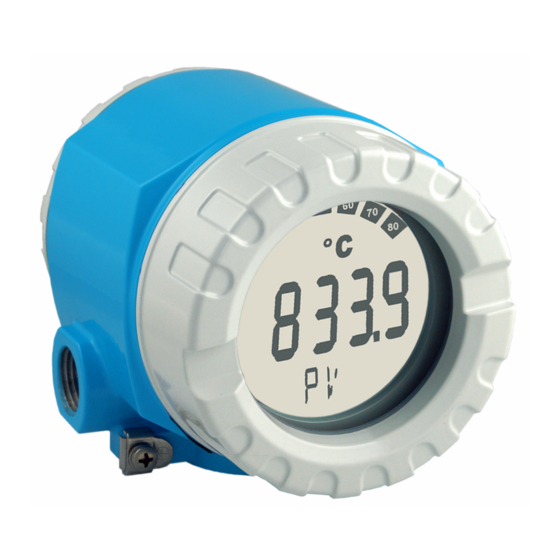
Endress+Hauser iTEMP TMT162 Operating Instructions Manual (160 pages)
Temperature field transmitter
Brand:
Endress+Hauser
| Category:
Transmitter
| Size: 5 MB
Table of Contents
Deutsch
4
Table of Contents
4
Sicherheitshinweise
5
Bestimmungsgemäße Verwendung
5
Montage, Inbetriebnahme, Bedienung
5
Betriebssicherheit
5
Rücksendung
5
Sicherheitszeichen und -Symbole
6
Identifizierung
7
Gerätebezeichnung
7
Typenschild
7
Lieferumfang
7
Zertifikate und Zulassungen
7
Montage auf einen Blick
8
Montage
8
Montagebedingungen
9
Abmessungen
9
Montageort
9
Montage
9
Direkte Sensormontage
9
Abgesetzte Montage
10
Montagekontrolle
10
Verdrahtung
11
Verdrahtung auf einen Blick
11
Anschluss Sensor
12
Anschluss Messeinheit
12
Anschluss HART
12
Schirmung und Potenzialausgleich
13
Schutzart
14
Anschlusskontrolle
14
Bedienung
15
Anzeige- und Bedienelemente
15
Anzeigedarstellung
15
Anzeigesymbole
15
Vor-Ort-Bedienung
16
Einstellung der Hardware
16
Kommunikation über HART® Protokoll
17
HART® Communicator DXR275/375
17
Fieldcare
19
Readwin® 2000
19
Kommandoklassen IM HART® -Protokoll
20
Quick-Setup
21
Installationskontrolle
21
Messgerät Einschalten
21
Inbetriebnahme
21
Gerätekonfiguration
22
Beschreibung Gerätefunktionen
22
Unterstützte HART® Kommandos
30
Wartung
32
Zubehör
32
Störungsbehebung
33
Fehlersuchanleitung
33
Fehlermeldungen
33
Korrosionserkennung
35
Überwachung der Versorgungsspannung
35
Applikationsfehler für RTD-Anschluss
36
Applikationsfehler Allgemein
36
Applikationsfehler ohne Meldungen
36
Applikationsfehler für TC-Anschluss
37
Ersatzteile
38
Rücksendung
39
Entsorgung
39
Software-/Firmwarehistorie
40
Technische Daten
41
Eingang
41
Ausgang
42
Hilfsenergie
43
Messgenauigkeit
43
Umgebungsbedingungen
46
Konstruktiver Aufbau
48
Zertifikate und Zulassungen
49
Ergänzende Dokumentation
49
Anhang
50
Die Callendar - Van Dusen Methode
50
Polynom RTD
52
Anwendung mit Readwin® 2000
52
Index
54
English
57
Designated Use
58
Installation, Commissioning and Operation
58
Safety Notes
58
Notes on Safety Conventions and Icons
59
Operational Safety
59
Returns
59
Certificates and Approvals
60
Delivery Contents
60
Identification
60
Legend Plate
60
Registered Trademarks
60
Unit Identification
60
Dimensions
61
Installation
61
Installation Conditions
61
Quick Installation Guide
61
Direct Installation to a Sensor
62
Installation
62
Installation Point
62
Installation Check
63
Remote Installation
63
Quick Wiring Guide
64
Wiring
64
Connecting the Measuring Unit
65
Connecting the Sensor
65
HART® Connection
65
Degree of Protection
66
Shielding and Potential Equalization
66
Connection Check
67
Display and Operating Elements
68
Display Icons
68
Display Indication
68
Operation
68
Local Operation
69
Setup of the Hardware
69
Communication Using the HART® Protocol
70
HART® Communicator DXR275/375
71
Fieldcare
72
Readwin® 2000
72
Command Classification in the HART
73
Protocol
73
Commissioning
74
Installation Check
74
Quick Setup
74
Switch on the Device
74
Description of Device Functions
75
Device Configuration
75
Supported HART® Commands
83
Accessories
85
Maintenance
85
Error Messages
86
Trouble-Shooting
86
Trouble-Shooting Instructions
86
Corrosion Detection
87
Application Errors for RTD Connection
88
Application Errors Without Messages
88
General Application Errors
88
Monitoring the Supply Voltage
88
Application Errors for TC Connection
89
Spare Parts
90
Disposal
91
Returns
91
Software-/Firmware History
92
Input
93
Technical Data
93
Output
94
Performance Characteristics
95
Power Supply
95
Environment Conditions
97
Mechanical Construction
99
Certificates and Approvals
100
Documentation
100
Appendix
102
The Callendar - Van Dusen Method
102
How to Use with Readwin® 2000
104
Polynomial RTD
104
Français
108
Conseils de Sécurité
109
Montage, Mise en Service, Exploitation
109
Retour de Matériel
109
Sécurité de Fonctionnement
109
Utilisation Conforme
109
Symboles de Sécurité Utilisés
110
Certificats et Agréments
111
Contenu de la Livraison
111
Désignation de L'appareil
111
Identification
111
Plaque Signalétique
111
Montage
112
Montage en Bref
112
Conditions de Montage
113
Dimensions
113
Lieu de Montage
113
Montage
113
Montage Direct du Capteur
113
Contrôle du Montage
114
Montage Déporté
114
Câblage
115
Câblage en Bref
115
Raccordement du Capteur
116
Raccordement HART
116
Raccordement Unité de Mesure
116
Blindage et Compensation de Potentiel
117
Contrôle du Raccordement
118
Protection
118
Affichage
119
Configuration
119
Eléments D'affichage et de Configuration
119
Symboles D'affichage
119
Configuration Sur Site
120
Réglage du Hardware
120
Communication Via Protocole HART
121
HART® Communicator DXR275/375
121
Fieldcare
123
Hart
123
Readwin® 2000
123
Contrôle de L'installation
124
Mettre L'appareil de Mesure Sous Tension
124
Mise en Service
124
Quick-Setup
124
Configuration D'appareil
125
Description des Fonctions D'appareil
125
Commandes Supportées Par HART
135
Accessoires
136
Maintenance
136
Messages D'erreur
137
Recherche des Défauts
138
Suppression des Défauts
138
Reconnaissance de Corrosion
139
Surveillance Tension D'alimentation
139
Erreur D'application en Général
140
Erreur D'application pour Raccordement RTD
140
Erreur D'application Sans Messages
140
Erreur D'application pour Raccordement TC
141
Mise au Rebut
143
Pièces de Rechange
143
Retour de Matériel
143
Historique Software/Logiciel
144
Entrée
145
Caractéristiques Techniques
146
Alimentation Électrique
147
Sortie
147
Précision de Mesure
149
Conditions Environnantes
150
Construction
152
Certificats et Agréments
154
Documentation Complémentaire
154
Annexe
156
La Méthode Callendar - Van Dusen
156
Application Avec Readwin® 2000
158
Index
158
Polynome RTD 158
158
Advertisement
Endress+Hauser iTEMP TMT162 Operating Instructions Manual (121 pages)
Temperature field transmitter
Brand:
Endress+Hauser
| Category:
Transmitter
| Size: 4 MB
Table of Contents
Operating Instructions
1
Table of Contents
3
1 Important Document Information
4
Electrical Symbols
4
Function of Document and How to Use
4
Safety Instructions
4
Symbols Used
4
Symbols for Certain Types of Information
5
Tool Symbols
5
Documentation
6
Registered Trademarks
6
2 Basic Safety Instructions
7
Designated Use
7
Operational Safety
7
Requirements for the Personnel
7
Workplace Safety
7
IT Security
8
Product Safety
8
Incoming Acceptance and Product Identification
9
Nameplate
10
Scope of Delivery
10
Transport and Storage
11
Direct Sensor Mounting
12
Installation Conditions
12
Mounting the Transmitter
12
Remote Mounting
13
Display Mounting
14
Post-Installation Check
14
Connecting the Sensor
15
Connection Conditions
15
5 Wiring
15
Terminal Assignment
16
Cable Glands or Entries
17
Connecting the HART Communication Resistor
17
Connecting the Measuring Device
17
Shielding and Grounding
18
Special Connection Instructions
19
Surge Arrester Function Test
19
Ensuring the Degree of Protection
20
Post-Connection Check
21
6 Operating Options
22
Overview of Operation Options
22
Display and Operating Elements
23
Procedure for Setting the DIP Switch or Activating the Proof Test
24
Structure and Function of the Operating Menu
25
Submenus and User Roles
26
Access to the Operating Menu Via the Operating Tool
27
Devicecare
27
Fieldcare
27
AMS Device Manager
28
Field Communicator 475
28
Field Xpert
28
Simatic Pdm
28
HART Device Variables and Measured Values
29
7 System Integration
29
Device Variables and Measured Values
30
Supported HART ® Commands
30
8 Commissioning
33
Enabling Configuration
33
Post-Installation Check
33
Switching on the Transmitter
33
9 Diagnostics and Troubleshooting
34
Displaying Diagnostic Events
36
Overview of Diagnostic Events
37
Endress+Hauser Services
40
10 Maintenance
40
Software History and Overview of Compatibility
40
General Notes
41
11 Repair
41
Spare Parts
41
Device-Specific Accessories
43
Disposal
43
Return
43
Communication-Specific Accessories
44
Service-Specific Accessories
44
System Products
45
Technical Data
46
13 Technische Daten
46
Power Supply
49
Performance Characteristics
50
Measured Error for Thermocouples (TC) and Voltage Transmitters
52
Environment
57
Mechanical Construction
59
Certificates and Approvals
60
Operating Menu and Parameter Description
62
"Setup" Menu
69
"Advanced Setup" Submenu
73
Drift/Difference Mode
73
Enter Access Code
73
Access Status Tooling
74
Locking Status
74
Drift/Difference Alarm Delay
75
Sensor Offset N
75
Drift/Difference Set Point
76
Sensor Switch Set Point
76
Failure Mode
77
Output Current
77
Current Trimming 20 Ma
78
Current Trimming 4 Ma
78
Failure Current
78
Reset Trim
78
Display Interval
79
Value 1 Display (Value 2 or 3 Display)
79
Decimal Places 1 (Decimal Places 2 or 3)
80
Display Text N
80
SIL Option
80
Enter SIL Checksum
81
Operational State
81
Deactivate SIL
82
Force Safe State
82
Restart Device
82
SIL Checksum
82
Define Device Write Protection Code
83
"Diagnose List" Submenu
84
"Diagnostics" Menu
84
Actual Diagnostics
84
Previous Diagnostics 1/Operating Time
84
Actual Diag Channel
85
Actual Diagnostics Count
85
Current Diagnostics
85
"Event Logbook" Submenu
86
Device Tag
86
Previous Diag N Channel
86
Previous Diagnostics N
86
Device Name
87
Firmware Version
87
Order Code
87
Serial Number
87
Configuration Counter
88
Device Temperature
88
Sensor N Value
88
"Sumulation" Submenu
89
Current Output Simulation
89
Device Temperature Min/Device Temperature Max
89
Sensor N Max Value
89
Value Current Output
90
"Expert" Menu
91
Damping
91
Alarm Delay
92
Mains Filter
92
Measurement Channels
92
Sensor N Lower Limit
94
Sensor N Upper Limit
94
Sensor Serial Number
94
Sensor Trimming
95
Sensor Trimming Lower Value
95
Sensor Trimming Upper Value
95
Sensor Trimming Min Span
96
Call./V. Dusen Coeff. A, B and C
97
Call./V. Dusen Coeff. R0
97
Polynomial Coeff. A, B
97
Polynomial Coeff. R0
97
Control
99
Start Value
99
Calibration Countdown
100
HART Address
101
HART Short Tag
101
Configuration Changed
102
Device Type
102
No. of Preambles
102
Reset Configuration Changed
102
Device ID
103
Device Revision
103
HART Revision
103
Manufacturer ID
103
Hardware Revision
104
HART Date Code
104
HART Descriptor/Hart Message
104
Software Revision
104
Latitude
105
Location Description
105
Longitude
105
Process Unit Tag
105
Altitude
106
Location Method
106
Pv
106
Assign SV
107
Assign TV
107
Sv
107
TV / Assign QV
107
Burst Command
108
Burst Mode
108
Qv
108
Burst Variable N
109
Burst Trigger Level
110
Burst Trigger Mode
110
Min. Update Period
110
Max. Update Period
111
Squawk
111
Extended Order Code 1-3
112
Manufacturer
113
Reset Device Temp. Min/Max Values
114
Reset Sensor Min/Max Values
114
Sensor N Raw Value
114
Diagnostic Behavior
115
Diagnostic Simulation
115
Status Signal
116
Endress+Hauser iTEMP TMT162 Operating Instructions Manual (156 pages)
Temperature field transmitter
Brand:
Endress+Hauser
| Category:
Measuring Instruments
| Size: 4 MB
Table of Contents
Deutsch
5
Table of Contents
5
Sicherheitshinweise
6
Bestimmungsgemäße Verwendung
6
Montage, Inbetriebnahme, Bedienung
6
Betriebssicherheit
6
Rücksendung
6
Sicherheitszeichen und -Symbole
7
Identifizierung
8
Gerätebezeichnung
8
Lieferumfang
8
Zertifikate und Zulassungen
8
Montage
9
Montage auf einen Blick
9
Montagebedingungen
10
Montage
10
Montagekontrolle
11
Verdrahtung auf einen Blick
12
Verdrahtung
12
Anschluss Sensor
13
Anschluss Messeinheit
13
Schirmung und Potenzialausgleich
14
Schutzart
15
Anschlusskontrolle
15
Bedienung
16
Anzeige- und Bedienelemente
16
Vor-Ort-Bedienung
17
Kommunikation über HART® Protokoll
18
Inbetriebnahme
21
Installationskontrolle
21
Messgerät Einschalten
21
Quick-Setup
21
Gerätekonfiguration
22
Wartung
32
Zubehör
32
Fehlermeldungen
33
Fehlersuchanleitung
33
Störungsbehebung
33
Applikationsfehler ohne Meldungen
36
Ersatzteile
38
Rücksendung
39
Entsorgung
39
Software-/Firmwarehistorie
40
Technische Daten
41
Anhang
49
Die Callendar - Van Dusen Methode
49
Polynom RTD
51
Index
52
English
57
Designated Use
58
Installation, Commissioning and Operation
58
Safety Notes
58
Notes on Safety Conventions and Icons
59
Operational Safety
59
Returns
59
Certificates and Approvals
60
Delivery Contents
60
Identification
60
Registered Trademarks
60
Unit Identification
60
Installation
61
Quick Installation Guide
61
Installation
62
Installation Conditions
62
Installation Check
63
Quick Wiring Guide
64
Wiring
64
Connecting the Measuring Unit
65
Connecting the Sensor
65
Shielding and Potential Equalization
66
Connection Check
67
Degree of Protection
67
Display and Operating Elements
68
Operation
68
Local Operation
69
Communication Using the HART® Protocol
70
Commissioning
74
Installation Check
74
Quick Setup
74
Switch on the Device
74
Device Configuration
75
Accessories
85
Maintenance
85
Error Messages
86
Trouble-Shooting
86
Trouble-Shooting Instructions
86
Application Errors Without Messages
88
Spare Parts
90
Disposal
91
Returns
91
Software-/Firmware History
92
Technical Data
93
Appendix
101
The Callendar - Van Dusen Method
101
Polynomial RTD
103
Index
104
Français
107
Conseils de Sécurité
108
Montage, Mise en Service, Exploitation
108
Retour de Matériel
108
Sécurité de Fonctionnement
108
Utilisation Conforme
108
Symboles de Sécurité Utilisés
109
Certificats et Agréments
110
Contenu de la Livraison
110
Désignation de L'appareil
110
Identification
110
Montage
111
Montage en Bref
111
Conditions de Montage
112
Montage
112
Contrôle du Montage
113
Câblage
114
Câblage en Bref
114
Raccordement du Capteur
115
Raccordement Unité de Mesure
115
Blindage et Compensation de Potentiel
116
Contrôle du Raccordement
117
Protection
117
Configuration
118
Eléments D'affichage et de Configuration
118
Configuration Sur Site
119
Communication Via Protocole HART
120
Contrôle de L'installation
123
Mettre L'appareil de Mesure Sous Tension
123
Mise en Service
123
Quick-Setup
123
Configuration D'appareil
124
Accessoires
134
Maintenance
134
Messages D'erreur
135
Recherche des Défauts
135
Suppression des Défauts
135
Erreur D'application Sans Messages
138
Pièces de Rechange
140
Mise au Rebut
141
Retour de Matériel
141
Historique Software/Logiciel
142
Caractéristiques Techniques
143
Annexe
151
La Méthode Callendar - Van Dusen
151
Polynome RTD
153
Index
154
Advertisement
Endress+Hauser iTEMP TMT162 Operating Instructions Manual (122 pages)
Temperature Field Transmitter HART Communication
Brand:
Endress+Hauser
| Category:
Transmitter
| Size: 4 MB
Table of Contents
Table of Contents
3
Symbols
4
About this Document
4
Function of Document and How to Use
4
Documentation
6
Registered Trademarks
7
Safety Instructions
8
Requirements for the Personnel
8
Intended Use
8
Workplace Safety
8
Operational Safety
8
Incoming Acceptance
9
Identification
9
Incoming Acceptance and Product
9
IT Security
9
Product Safety
9
Product Identification
10
Certificates and Approvals
10
Storage and Transport
10
Mounting
12
Mounting Requirements
12
Mounting the Transmitter
12
Display Mounting
14
Post-Mounting Check
14
Connecting the Sensor
15
Connecting Requirements
15
Electrical Connection
15
Connecting the Measuring Instrument
17
Special Connection Instructions
19
Ensuring the Degree of Protection
21
Post-Connection Check
21
Operation Options
22
Overview of Operation Options
22
Structure and Function of the Operating Menu
25
Access to the Operating Menu Via the Operating Tool
27
System Integration
30
HART Device Variables and Measured Values
30
Device Variables and Measured Values
31
Supported HART Commands
31
Commissioning
33
Function Check
33
Switching on the Device
33
Protecting Settings from Unauthorized Access
33
Diagnosis and Troubleshooting
35
General Trouble Shooting
35
Overview of Diagnostic Information
37
Diagnostic List
38
Cleaning
41
Firmware History
41
Maintenance
41
Repair
42
General Notes
42
Spare Parts
42
Return
44
Disposal
44
Accessories
44
Device-Specific Accessories
44
Service-Specific Accessories
45
System Products
45
Technical Data
47
Input
47
Output
48
Power Supply
51
Performance Characteristics
52
Environment
59
Mechanical Construction
61
Certificates and Approvals
62
Operating Menu and Parameter
63
Description
63
Endress+Hauser
64
Actual Diagnostics 1 to 3
68
Operating Time
68
Previous Diagnostics 1
68
Reset Backup
68
Setup" Menu
70
Failure Current
79
Failure Mode
79
Ma Current Trimming
79
Output Current
79
20 Ma Current Trimming
80
Display Interval
80
Reset Trim
80
Display Text
81
Value 1 Display
81
Operational State
82
SIL Option
82
Deactivate SIL
83
Force Safe State
83
SIL Checksum
83
Device Reset
84
Expert Mode
84
Restart Device
84
Diagnostics" Menu
86
Expert" Menu
93
Index
119
Endress+Hauser iTEMP TMT162 Operating Instructions Manual (56 pages)
Temperature field transmitter
Brand:
Endress+Hauser
| Category:
Transmitter
| Size: 6 MB
Table of Contents
Brief Overview
4
Safety Message
4
Table of Contents
5
Safety Notes
6
Designated Use
6
Installation, Commissioning and Operation
6
Operational Safety
7
Hazardous Areas
7
Returns
7
Safety Pictograms and Symbols
7
Identification
8
Unit Identification
8
Delivery Contents
8
Registered Trademarks
9
Installation
9
Quick Installation Guide
9
Installation Conditions
10
Installation Point
10
Installation
10
Installation Check
10
Wiring
11
Quick Wiring Guide
11
Terminal Layout
11
Connecting the Sensor
12
Connecting the Measuring Unit
12
HART ® Connection
12
Screening and Potential Equalisation
13
Degree of Protection
14
Connection Check
14
Operation
15
Display and Operating Elements
15
Local Operation
16
Communication Using the HART® Protocol
17
Commissioning
20
Installation Check
20
Switch on the Device
20
Quick Setup
20
Device Configuration
21
Description of Device Functions
21
Supported HART ® Commands
29
Maintenance
31
Accessories
31
Trouble-Shooting
31
Trouble-Shooting Instructions
31
Error Messages
31
Application Errors Without Messages
34
Spare Parts
36
Returns
37
Disposal
37
Software History
38
Technical Data
39
Power Supply
40
Performance Characteristics
40
Ambient Temperature Limits
42
Environment Conditions
42
Endress+Hauser iTEMP TMT162 Brief Operating Instructions (48 pages)
Temperature field transmitter
Brand:
Endress+Hauser
| Category:
Transmitter
| Size: 2 MB
Table of Contents
Deutsch
3
Table of Contents
3
Sicherheitshinweise
4
Bestimmungsgemäße Verwendung
4
Montage, Inbetriebnahme, Bedienung
4
Betriebssicherheit
4
Rücksendung
5
Sicherheitszeichen und -Symbole
5
Montage
6
Montage auf einen Blick
6
Montagebedingungen
7
Montage
7
Montagekontrolle
8
Verdrahtung
9
Verdrahtung auf einen Blick
9
Anschluss Sensor
10
Geräteanschluss
10
Schirmung und Potenzialausgleich
12
Schutzart
12
Anschlusskontrolle
13
Inbetriebnahme
14
Installations- und Funktionskontrolle
14
Einschalten des Gerätes
14
Anzeige- und Bedienelemente
14
English
17
Designated Use
18
Installation, Commissioning and Operation
18
Operational Safety
18
Safety Instructions
18
Notes on Safety Conventions and Icons
19
Return
19
Installation Instructions
20
Quick Installation Guide
20
Installation Conditions
21
Installation Instructions
21
Post-Installation Check
22
Quick Wiring Guide
23
Wiring
23
Connecting the Device
24
Connecting the Sensor
24
Degree of Protection
26
Shielding and Potential Equalization
26
Connection Check
27
Commissioning
28
Display and Operating Elements
28
Function Check
28
Switching on the Device
28
Français
31
Conseils de Sécurité
32
Montage, Mise en Service, Exploitation
32
Sécurité de Fonctionnement
32
Utilisation Conforme
32
Retour de Matériel
33
Symboles de Sécurité Utilisés
33
Montage
34
Montage en Bref
34
Conditions de Montage
35
Montage
35
Contrôle du Montage
36
Câblage
37
Câblage en Bref
37
Raccordement Capteur
38
Raccordement Unité
38
Blindage Et Compensation de Potentiel
40
Protection
40
Contrôle du Raccordement
41
Contrôle de L'installation Et du Fonctionnement
42
Eléments D'affichage Et de Configuration
42
Mise en Service
42
Mise Sous Tension de L'appareil
42
Endress+Hauser iTEMP TMT162 Brief Operating Instructions (52 pages)
Dual-input temperature field transmitter with PROFIBUS PA protocol
Brand:
Endress+Hauser
| Category:
Measuring Instruments
| Size: 2 MB
Table of Contents
Deutsch
4
1 Wichtige Hinweise zum Dokument
4
Table of Contents
4
Funktion und Umgang mit dem Dokument
4
Verwendete Symbole
5
Anforderungen an das Personal
6
Bestimmungsgemäße Verwendung
6
Eingetragene Marken
6
2 Grundlegende Sicherheitshinweise
6
Arbeitssicherheit
7
Betriebssicherheit
7
Produktsicherheit
7
Warenannahme
8
3 Warenannahme und Produktidentifikation
8
Produktidentifikation
9
Transport und Lagerung
10
Kurzanleitung
10
4 Montage
11
Montagebedingungen
11
Transmitter Montieren
11
Anschlussbedingungen
14
5 Elektrischer Anschluss
14
Montagekontrolle
14
Sensor Anschließen
15
Messgerät Anschließen
16
Schutzart Sicherstellen
19
Anschlusskontrolle
20
6 Bedienmöglichkeiten
21
Übersicht zu Bedienungsmöglichkeiten
21
Messwertanzeige- und Bedienelemente
22
Einschalten des Transmitters
25
7 Inbetriebnahme
25
Installations- und Funktionskontrolle
25
English
27
1 Important Document Information
27
Function of Document and How to Use
27
Symbols Used
28
2 Basic Safety Instructions
29
Designated Use
29
Registered Trademarks
29
Requirements for Personnel
29
Workplace Safety
29
Operational Safety
30
Product Safety
30
Incoming Acceptance
31
3 Incoming Acceptance and Product Identification
31
Product Identification
32
4 Installation
33
Transport and Storage
33
Installation Conditions
34
Mounting the Transmitter
34
Connection Conditions
37
5 Electrical Connection
37
Post-Installation Check
37
Connecting the Sensor
38
Connecting the Measuring Device
39
Ensuring the Degree of Protection
42
Post-Connection Check
43
6 Operating Options
44
Overview of Operating Options
44
Display and Operating Elements
45
7 Commissioning
48
Function Check
48
Switching on the Transmitter
48
Endress+Hauser iTEMP TMT162 Operating Instructions Manual (56 pages)
Temperature field transmitter
Brand:
Endress+Hauser
| Category:
Transmitter
| Size: 1 MB
Table of Contents
Table of Contents
3
1 Safety Notes
4
Designated Use
4
Installation, Commissioning and Operation
4
Operational Safety
5
Returns
5
Safety Pictograms and Symbols
5
2 Identification
6
Unit Identification
6
Delivery Contents
6
Registered Trademarks
7
3 Installation
7
Quick Installation Guide
7
Installation Conditions
8
Installation
8
Installation Check
9
4 Wiring
10
Quick Wiring Guide
10
Connecting the Sensor
11
Connecting the Measuring Unit
11
Shielding and Potential Equalization
12
Degree of Protection
13
Connection Check
13
5 Operation
14
Display and Operating Elements
14
Local Operation
15
Communication Using the HART® Protocol
16
6 Commissioning
20
Installation Check
20
Switch on the Device
20
Quick Setup
20
Device Configuration
21
7 Maintenance
32
8 Accessories
32
9 Trouble-Shooting
33
Trouble-Shooting Instructions
33
Error Messages
33
Application Errors Without Messages
35
Spare Parts
38
Returns
40
Disposal
40
Software History
40
10 Technical Data
42
11 Appendix
51
The Callendar - Van Dusen Method
51
Polynomial RTD
53
Index
54
Endress+Hauser iTEMP TMT162 Brief Operating Instructions (24 pages)
Temperature field transmitter HART communication
Brand:
Endress+Hauser
| Category:
Transmitter
| Size: 3 MB
Table of Contents
Table of Contents
3
About this Document
3
Function of Document and How to Use
3
Symbols
4
Safety Instructions
5
Requirements for the Personnel
5
Intended Use
5
Workplace Safety
6
Operational Safety
6
Product Safety
6
Incoming Acceptance and Product Identification
6
Incoming Acceptance
6
Product Identification
7
Certificates and Approvals
8
Storage and Transport
8
Mounting
8
Mounting Requirements
8
Mounting the Transmitter
9
Post-Mounting Check
12
Electrical Connection
12
Connecting Requirements
12
Connecting the Sensor
13
Connecting the Measuring Device
15
Special Connection Instructions
17
Ensuring the Degree of Protection
18
Post-Connection Check
18
Operation Options
19
Overview of Operation Options
19
Access to the Operating Menu Via the Operating Tool
22
Commissioning
22
Post-Installation Check
22
Switching on the Device
22
Maintenance
23
Cleaning
23
Endress+Hauser iTEMP TMT162 Brief Operating Instructions (24 pages)
Temperature field transmitter
Brand:
Endress+Hauser
| Category:
Transmitter
| Size: 2 MB
Table of Contents
Table of Contents
3
About this Document
3
Function of Document and How to Use
3
Symbols
4
Safety Instructions
5
Requirements for the Personnel
5
Intended Use
5
Workplace Safety
5
Operational Safety
6
Product Safety
6
Incoming Acceptance and Product Identification
6
Incoming Acceptance
6
Product Identification
7
Certificates and Approvals
7
Storage and Transport
8
Mounting
8
Mounting Requirements
8
Mounting the Transmitter
9
Post-Mounting Check
11
Electrical Connection
11
Connecting Requirements
11
Connecting the Sensor
12
Connecting the Measuring Device
14
Ensuring the Degree of Protection
15
Post-Connection Check
16
Operation Options
17
Overview of Operation Options
17
Measured Value Display and Operating Elements
18
Commissioning
21
Function Check
21
Switching on the Transmitter
21
Maintenance
22
Cleaning
22
Endress+Hauser iTEMP TMT162 Technical Information (25 pages)
Temperature field transmitter with HART, FOUNDATION Fieldbus or PROFIBUS PA protocol
Brand:
Endress+Hauser
| Category:
Transmitter
| Size: 1 MB
Table of Contents
Technical Information
1
Function and System Design
2
Equipment Architecture
3
Output Signal
5
Protocol-Specific Data
7
Switch-On Delay
9
Power Supply
9
Electrical Connection
9
Performance Characteristics
10
Installation Conditions
12
Environment Conditions
12
Mechanical Construction
14
Design, Dimensions
14
Human Interface
15
Certificates and Approvals
16
Product Structure
19
Ordering Information
19
Endress+Hauser iTEMP TMT162 Safety Instructions (12 pages)
Temperature field transmitter
Brand:
Endress+Hauser
| Category:
Transmitter
| Size: 0 MB
Advertisement
Related Products
Endress+Hauser tmt142
Endress+Hauser TMT122
Endress+Hauser iTEMP PCP TMT 121
Endress+Hauser iTEMP TMT125
Endress+Hauser iTEMP TMT112
Endress+Hauser HART iTEMP TMT182B
Endress+Hauser iTEMP TMT111
Endress+Hauser iTEMP TMT82
Endress+Hauser iTEMP TMT71
Endress+Hauser iTEMP TMT84
Endress+Hauser Categories
Measuring Instruments
Transmitter
Radar
Switch
Accessories
More Endress+Hauser Manuals
Login
Sign In
OR
Sign in with Facebook
Sign in with Google
Upload manual
Upload from disk
Upload from URL