Symmetricom TimeProvider 1000 User Manual
Edge clock
Hide thumbs
Also See for TimeProvider 1000:
- User manual (298 pages) ,
- Release notice (8 pages) ,
- Reference manual (180 pages)

Related Manuals for Symmetricom TimeProvider 1000


Summary of Contents for Symmetricom TimeProvider 1000
- Page 1 TimeProvider 1000 and 1100 Edge Clock User Guide Revision C – August 2005 Part Number 097-58001-02...
- Page 2 2300 Orchard Parkway San Jose, CA 95131-1017 U.S.A. http://www.symmetricom.com Copyright © 2003–2005 Symmetricom, Inc. All rights reserved. Printed in U.S.A. All product names, service marks, trademarks, and registered trademarks used in this document are the property of their respective owners.
-
Page 3: Table Of Contents
Table of Contents Contents How to Use This Guide Purpose of This Guide ..........xiv Who Should Read This Guide . - Page 4 Table of Contents BesTime ............39 Normal Tracking .
- Page 5 Table of Contents Chapter 4 Provisioning the TimeProvider TL1 Overview ............80 TL1 Command Structure .
- Page 6 Table of Contents Provisioning Alarms ..........114 Provisioning the Alarm Levels .
- Page 7 Mechanical ............194 TimeProvider 1000 Front-Access Shelf......194 TimeProvider 1100 Rear-Access Shelf .
- Page 8 Table of Contents Default Output Parameters ......... . . 204 Overview .
- Page 9 TimeProvider 1100 Expansion Panel ......TimeProvider 1000 - Front Panel ....... . .
- Page 10 List of Figures TimeProvider User’s Guide 097-58001-02 Revision C – August 2005...
- Page 11 List of Tables Tables Typical Power Consumption ........30 SSU-Based Reference Selection Scenarios.
- Page 12 List of Tables Default Access Levels for TL1 Commands......198 Default Alarm Settings ......... . 199 Default Equipment Parameters.
- Page 13 How to Use This Guide This section describes the format, layout, and purpose of this guide. In This Preface Purpose of This Guide Who Should Read This Guide Structure of This Guide Conventions Used in This Guide Warnings, Cautions, Recommendations, and Notes Related Documents and Information Where to Find Answers to Product and Document Questions What’s New in This Document...
-
Page 14: Purpose Of This Guide
How to Use This Guide Purpose of This Guide The TimeProvider User’s Guide describes the procedures for unpacking, installing, using, maintaining, and troubleshooting the Symmetricom TimeProvider. It also includes appendixes that describe default values and how to install the included software application SynCraft. -
Page 15: Conventions Used In This Guide
A re-timing application A word or term being emphasized. Symmetricom does not A word or term given special emphasis. recommend... Warnings, Cautions, Recommendations, and Notes Warnings, Cautions, Recommendations, and Notes attract attention to essential or critical information in this guide. - Page 16 How to Use This Guide Warning: To avoid serious personal injury or death, do not disregard warnings. All warnings use this symbol. Warnings are installation, operation, or maintenance procedures, practices, or statements, that if not strictly observed, may result in serious personal injury or even death.
-
Page 17: Related Documents And Information
Where to Find Answers to Product and Document Questions For additional information about the products described in this guide, please contact your Symmetricom representative or your local sales office. You can also contact us on the web at www.symmetricom.com. What’s New in This Document This guide includes the following new topic: Addition of the Retimer module. - Page 18 How to Use This Guide xviii TimeProvider User’s Guide 097-58001-02 Revision C – August 2005...
-
Page 19: Chapter 1 Overview Of The Timeprovider
Chapter 1 Overview of the TimeProvider This chapter describes the TimeProvider product. In This Chapter Overview Operating Modes Performance Monitoring Physical Description Functional Description System Power Communication Ports Reference Input Signals Clock Performance Output Signals Alarms Synchronization Status Messages (SSMs) SmartClock BesTime 097-58001-02 Revision C –... -
Page 20: Overview
32 redundant universal timing outputs; an optional Expansion Panel provides an additional 32 redundant outputs. Using Symmetricom’s SmartClock™ technology design, the oscillators within the IOCs are enhanced with improved performance and accuracy. Using intelligent firmware algorithms, SmartClock “learns” the effects of the ageing of the clock while it is locked to a reference signal and stores this information in its memory. -
Page 21: Shelves
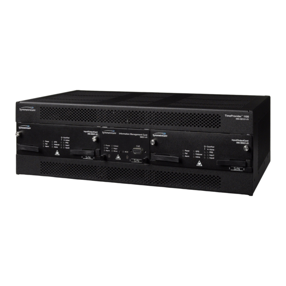
Shelves The TimeProvider is available in two shelf models. Each shelf supports up to 32 redundant output channels. The TimeProvider 1000 is a 175 mm tall ETSI shelf that meets the requirements of ETSI 300 119-4 January 1994. Figure 1-1 shows the TimeProvider 1000 shelf. -
Page 22: Expansion Panel
Chapter 1 Overview of the TimeProvider Overview Figure 1-2. TimeProvider 1100 Rear Access Shelf Expansion Panel The TimeProvider has an optional Expansion Panel that doubles (to 64) the number of output channels available. Figure 1-3 shows the rear-access version of the Expansion Panel. -
Page 23: Outputs
Chapter 1 Overview of the TimeProvider Overview The TimeProvider qualifies the input reference signals and detect the following errors: Loss of Signal (LOS), Alarm Indication Signal (AIS), Loss of Framing, and Synchronization Status Messages (SSM) where applicable. Reference Input Signals, on page 32, describes the inputs in more detail. Outputs The TimeProvider produces a variety of outputs to meet different signal standards. -
Page 24: Operating Modes
PRS, INP1, or INP2 connectors are used in conjunction with BesTime to extend compliance with GR-2830/G.812 standards. The PRR mode uses Symmetricom’s BesTime servo control that allows the TimeProvider to continue providing outputs in case GPS tracking is lost, the GPS data loses integrity, or if the IMC is removed from the shelf. -
Page 25: Performance Monitoring
Chapter 1 Overview of the TimeProvider Performance Monitoring Performance Monitoring The TimeProvider can monitor and qualify all enabled input signals based on phase measurements. It measures the phase differences between the inputs and the output of the corrected clock. From these phase measurements, the TimeProvider computes frequency offset and wander of the input signals. -
Page 26: Tdev Calculations
(Model 1000) and rear access (Model 1100), as shown Figure 1-1 Figure 1-2. Figure 1-4 illustrates the location of the connectors, cards, and modules in the TimeProvider 1000. TimeProvider User’s Guide 097-58001-02 Revision C – August 2005... -
Page 27: Timeprovider 1000 - Front Panel
Connector Connector Input Module IOC 1 Local Craft IOC 2 Connector Figure 1-4. TimeProvider 1000 - Front Panel Figure 1-5 illustrates the location of the connectors, cards, and modules in the TimeProvider 1100. Power Remote Serial Expansion Ethernet Power Connector... -
Page 28: Functional Description
Chapter 1 Overview of the TimeProvider Functional Description Functional Description The TimeProvider consists of a main shelf and slots for two IOCs and one IMC. One plug-in Input module and up to four plug-in Output modules complete the main shelf, which provides up to 32 outputs. The optional Expansion Panel can provide up to 32 additional outputs, to provide a total of 64 outputs. - Page 29 Chapter 1 Overview of the TimeProvider Functional Description Input Module The Input module receives the incoming reference signals and contains the alarm input/output connector. A variety of connector modules allows you to select the connector style and input impedance to match the wiring system at the installation site. Information Management Card (IMC) The Information Management Card, known as the IMC, contains a processor that manages communications between the two IOCs and the serial and Ethernet...
-
Page 30: System Power
Chapter 1 Overview of the TimeProvider System Power Output Module The Output module provides the output connectors for the TimeProvider. You can install up to four Output modules on the main shelf. Like the Input module, each Output module uses one of a variety of connectors that match the wiring system at the installation site. -
Page 31: Communication Ports
This EIA-232 port supports local control; you can configure the TimeProvider with TL1 commands using a terminal or personal computer (PC) with terminal emulation software or Symmetricom’s craft software, SynCraft. The connector is located on the front panel of the IMC. The default specifications are 9600-8-N-1. The Local port is configured as a DCE interface. -
Page 32: Reference Input Signals
Chapter 1 Overview of the TimeProvider Reference Input Signals Reference Input Signals The Input module accepts one or two E1, 2.048 MHz analog, 1.544 MHz or 6.312 MHz analog (Japan-specific), T1, and Composite Clock (including JCC and JCC4) inputs on ports INP1 and INP2. The CC inputs are used solely for Subtending mode;... -
Page 33: Ssms And Quality Level
Chapter 1 Overview of the TimeProvider Reference Input Signals Revertive Switching Telcordia GR-378 and GR-1244 define two reference selection modes: Revertive and Non-revertive. In the revertive mode, when an input used as the system reference is disqualified (for any reason), if that input returns, it reverts to the system reference when the disqualifying reason is removed. -
Page 34: Ssu-Based Reference Selection Scenarios
Chapter 1 Overview of the TimeProvider Reference Input Signals If the incoming signal does not include SSMs, or if you disable them, then you can provision the Quality Level to an appropriate value. The QLEVEL value is used in the same manner as the incoming SSM to determine which input is used when the active input is disqualified. -
Page 35: Gps Inputs
Non-revertive example. Priority Levels set to: INP1 = 3, and INP2 = 3 Revertive example. Priority Levels set to: INP1 = 1, and INP2 = 2 GPS Inputs Symmetricom provides a complete GPS antenna system for the TimeProvider. This includes the Symmetricom GPS Antenna, the TimeProvider Interface Unit (TPIU), and associated cables. -
Page 36: Clock Performance
Chapter 1 Overview of the TimeProvider Clock Performance Clock Performance Two IOCs are available: A Rubidium-based version that meets ST2/Type II standards. This IOC meets or exceeds the ITU G.812 Type II specification. A Quartz-based version that meets ST3E/Type I standards. This IOC meets or exceeds the ST3E requirements in ANSI T1.101 and Telcordia GR-1244, as well as the ITU-T G.812 TYPE III specification and ITU-T G.812 Type I specification. -
Page 37: Alarms
A similar timer (CLRDELAY) clears the alarm after the alarm condition is no longer present. Recommendation: To prevent Non-Service Affecting LOS alarms, Symmetricom recommends that you provision unused inputs to the Disabled state. For more information on connecting alarms, see... -
Page 38: Itu Ssm Quality Level Definitions
Chapter 1 Overview of the TimeProvider Synchronization Status Messages (SSMs) Table 1-4. ANSI SSM Quality Level Definitions (Continued) Description Quality Level Abbreviation SONET Minimum Clock traceable (20 ppm clock) Stratum 4 traceable (32 ppm clock) Do Not Use for synchronization Table 1-5. -
Page 39: Smartclock
BesTime The TimeProvider uses Symmetricom’s BesTime algorithm when it is in the PRR mode to provide enhanced GR-2830-CORE performance during bridging or holdover situations. BesTime minimizes the effect of transients on the reference signal on the outputs of the TimeProvider by comparing them against the system reference to produce the most stable outputs from the TimeProvider. -
Page 40: Normal Tracking
Chapter 1 Overview of the TimeProvider BesTime The BesTime algorithm is based on Symmetricom’s patented use of multiple-input phase-locked loops (MPLLs) to generate a correction signal for the local oscillator (LO) in the IOC. With GPS as the primary input signal in PRR mode, the signals on... -
Page 41: Chapter 2 Engineering And Ordering Procedures
Chapter 2 Engineering and Ordering Procedures This chapter describes the items available with the TimeProvider, and lists the part number for each item. In This Chapter Shelf Expansion Panel Input Modules Output Modules IMC and IOC Modules GPS Antenna Ordering and Parts List Accessories, Tools, and Equipment 097-58001-02 Revision C –... -
Page 42: Shelf
Chapter 2 Engineering and Ordering Procedures Shelf Shelf The TimeProvider is available in two configurations: Model 1000 Front Access and Model 1100 Rear Access. Model 1000 Front Access The ETSI-style shelf (990-58001-01) complies with ETSI 300-119 shelf projections. Each shelf accepts one IMC and one or two IOCs; the shelf also supports one Input module and from one to four Output modules. -
Page 43: Rear Access
Metric (Siemens) 1.6/5.6 Input module Output Modules Symmetricom has seven Output modules available for the TimeProvider that allow you to select the proper termination for your application. You can install any combination of up to four Output modules in the main shelf or in the available Expansion Panel. -
Page 44: Imc And Ioc Modules
Blank module (cover for any unused Output module locations) IMC and IOC Modules Symmetricom has several modules available for the TimeProvider that provide varying levels of clock stability. You can install any combination of IOC modules in the main shelf. -
Page 45: Gps Antenna
Chapter 2 Engineering and Ordering Procedures GPS Antenna GPS Antenna The following table identifies the parts available for the GPS antenna. Table 2-4. GPS Parts and Accessories Part Number Description 990-58545-01 TimeProvider Integrated GPS Antenna Kit, Rear Access 990-58545-02 TimeProvider Integrated GPS Antenna Kit, Front Access 090-58545-01 TimeProvider GPS Antenna 090-58545-21... -
Page 46: Ordering And Parts List
Chapter 2 Engineering and Ordering Procedures Ordering and Parts List Ordering and Parts List All IOCs, IMCs, and Input and Output Connector modules are sold separately. Use Table 2-5 to identify the available TimeProvider shelf types. Table 2-5. TimeProvider Shelves Model Outputs Part Number... -
Page 47: Chapter 3 Installing The Timeprovider
Chapter 3 Installing the TimeProvider This chapter describes the procedures for installing the TimeProvider shelf and the available Expansion Panel. In This Chapter Getting Started Unpacking the Unit Rack Mounting the Shelf and Expansion Panel Making Connections Installation Check List Powering Up the Shelf Working With Cards 097-58001-02 Revision C –... -
Page 48: Getting Started
Chapter 3 Installing the TimeProvider Getting Started Getting Started Before beginning the installation, complete the pre-installation check described in Pre-Installation Check, on page 48, perform the site survey in Performing a Site Survey, on page 48, and gather the necessary tools and materials described in Gathering the Tools, on page 49. -
Page 49: Gathering The Tools
Chapter 3 Installing the TimeProvider Getting Started Use only shielded cable for all signal wiring, including I/O, clocks and Ethernet, and ground appropriately at both ends, or as required by local standards. Secure all cable screws to their corresponding connectors. Caution: To avoid interference to the TimeProvider, you must consider the electromagnetic compatibility (EMC) of nearby equipment when preparing to install the TimeProvider. -
Page 50: Unpacking The Unit
1. Wear a properly grounded protective wrist strap or other ESD device. 2. Inspect the container for signs of damage. If the container appears to be damaged, notify both the carrier and your Symmetricom distributor. Retain the shipping container and packing material for the carrier to inspect. -
Page 51: Rack Mounting The Shelf And Expansion Panel
Chapter 3 Installing the TimeProvider Rack Mounting the Shelf and Expansion Panel Rack Mounting the Shelf and Expansion Panel The installation procedure described in this section provides general guidelines for installing the shelf and the optional Expansion panel. Always follow applicable local electrical codes. -
Page 52: Installing The Model 1100 Shelf And Expansion Panel - 19-Inch Rack
Chapter 3 Installing the TimeProvider Rack Mounting the Shelf and Expansion Panel Figure 3-2. Installing the Model 1100 Shelf and Expansion Panel - 19-inch Rack TimeProvider User’s Guide 097-58001-02 Revision C – August 2005... -
Page 53: Installing The Model 1000 Shelf And Expansion Panel - 23-Inch Rack
Chapter 3 Installing the TimeProvider Rack Mounting the Shelf and Expansion Panel Figure 3-3. Installing the Model 1000 Shelf and Expansion Panel - 23-inch Rack Figure 3-4. Installing the Model 1100 Shelf and Expansion Panel - 23-inch Rack 097-58001-02 Revision C – August 2005 TimeProvider User’s Guide... -
Page 54: Making Connections
After installing the TimeProvider shelf and/or the Expansion panel into the rack, make the grounding connections as follows. Recommendation: Although there are a number of methods for connecting the equipment to earth ground, Symmetricom recommends running a cable of the shortest possible length from the ground lug to earth ground. -
Page 55: Power Terminal Connectors
Chapter 3 Installing the TimeProvider Making Connections To install the TimeProvider power connections: 1. Assemble a power connector appropriate for the type of shelf. Table 3-1 lists the pin-out for each type of connector. Rear-access shelf: Crimp a No. 16 AWG (minimum) wire (1.31 mm ) to each pin, then slide the pin into the shell. -
Page 56: Verifying Power And Grounding Connections
Chapter 3 Installing the TimeProvider Making Connections Figure 3-6. Assembling the ETSI Power Connector Expansion Panel All connections to the Expansion Panel, including power, are made using the interconnection cable, part number 060-58002-03. Verifying Power and Grounding Connections To verify power and grounding connections: 1. -
Page 57: Making Input Connections
Chapter 3 Installing the TimeProvider Making Connections Making Input Connections You connect the input signals to the TimeProvider using one of the Input modules listed in Table 3-2. Connect the Input module to the shelf before you attach cables. Table 3-2. Input Connector Modules Available for the IOC Item Number Description Alarm Connector... -
Page 58: Wire-Wrap Input Module
Chapter 3 Installing the TimeProvider Making Connections Figure 3-8. Wire-Wrap Input Module Figure 3-9. DB9 Input Module The pinout for the DB9 Input module is shown in Table 3-3. Table 3-3. Pinout for the DB9 Input Module Description Chassis ground Span Input Tip Span Input Ring TimeProvider User’s Guide... -
Page 59: Bt43 Input Module
Chapter 3 Installing the TimeProvider Making Connections Figure 3-10. BT43 Input Module Figure 3-11. Metric (Siemens) Input Module 097-58001-02 Revision C – August 2005 TimeProvider User’s Guide... -
Page 60: Making Output Connections
Chapter 3 Installing the TimeProvider Making Connections Making Output Connections You make the output signal connections using one of the Output modules listed in Table 3-4. Attach the module to the shelf before you connect cables. Table 3-4. Output Connector Modules Item Number Description Reference... -
Page 61: Bnc And Wire-Wrap Output Modules
Chapter 3 Installing the TimeProvider Making Connections Figure 3-12. BNC and Wire-Wrap Output Modules Figure 3-13. DB9 and BT43 Output Modules 097-58001-02 Revision C – August 2005 TimeProvider User’s Guide... -
Page 62: Making Retimer Connections
Chapter 3 Installing the TimeProvider Making Connections Figure 3-14. Metric (Siemens) Output Module and T1 Retimer Wirewrap Output Module Making Retimer Connections The Retimer module (shown in Figure 3-14) performs reshaping, reamplifying, and retiming on a signal connected to the IN pins on Side 1 (East) and sends that signal to a Network Element (NE) connected to the OUT pins on Side 1. -
Page 63: Making Alarm Connections
Chapter 3 Installing the TimeProvider Making Connections Figure 3-15. Making Retimer Connections Making Alarm Connections To install alarm connections on the Input Module, use a customer-supplied DB-25 connector to build an alarm connection to the TimeProvider. Table 3-6 lists the pinout for the DB-25 Alarm connector found on all the Input modules (except the wire wrap version). -
Page 64: Making Gps Connections
Chapter 3 Installing the TimeProvider Making Connections Table 3-6. Alarm Connector Pinout (Continued) Description Critical NC Audible Critical Common Audible Critical NC Visual Critical Common Visual Ground Minor Normally Open (NO) Audible Critical PRS Input NO Minor NO Visual Critical PRS Input Common Major NO Audible Major PRS Input NO Major NO Visual... -
Page 65: Locating The Gps Antenna
Recommendation: The TimeProvider uses an antenna that requires a minimum cable length of 20 feet (6 m) from the antenna to the TPIU. Symmetricom recommends that you adhere to this minimum length requirement to ensure proper antenna operation. 097-58001-02 Revision C – August 2005... -
Page 66: Antenna-To-Shelf Cabling
Chapter 3 Installing the TimeProvider Making Connections Recommendation: Symmetricom recommends that you use one of the following grounding points: Valid roof ring ground system. Cad weld to building structural steel. Central office ground plate within 15 m of antenna cable entrance into building. -
Page 67: Installing The Antenna Bracket On A Pipe
Chapter 3 Installing the TimeProvider Making Connections To install the antenna: 1. Attach the antenna mounting bracket to a 1-inch (2.5 cm) diameter pipe or wood post. – If you are mounting the bracket to a pipe, assemble as shown in Figure 3-19. -
Page 68: Attaching The Antenna To The Bracket
Chapter 3 Installing the TimeProvider Making Connections 2. Connect the mast to the flange using PVC glue. 3. Feed an RG58 (060-58545-xx) cable through the bottom of the mast as illustrated. Table 2-4 for specific cable lengths. 4. Connect the cable to the antenna “pigtail” and pull the cable back through the mast. 5. -
Page 69: Assembling The Lightning Suppressor
Chapter 3 Installing the TimeProvider Making Connections 7. Using a plumb line or bubble level, ensure the antenna is within 5° of vertical (perpendicular to the horizon), and tighten the mounting bracket bolts. 8. Bolt the lightning suppressor mounting plate to a flange that is attached to a valid earth ground. - Page 70 17.Coat all exposed connectors with an electrically conductive antioxidant compound (e.g. Kopr-Shield spray). Installing the TPIU You mount the TPIU on a rack near the TimeProvider main shelf. Symmetricom supplies the connecting cable (060-58543-xx or 060-58544-xx) in several lengths, as listed in Table 2-4.
-
Page 71: Mounting The Tpiu And Expansion Panel On The Same Rack Ears
Chapter 3 Installing the TimeProvider Making Connections Figure 3-23. Mounting the TPIU and Expansion Panel on the Same Rack Ears Figure 3-24. Mounting the TPIU with a Model 1000 ETSI-Style Shelf 097-58001-02 Revision C – August 2005 TimeProvider User’s Guide... -
Page 72: Making Communications Connections
Chapter 3 Installing the TimeProvider Making Connections Making Communications Connections The Time Provider has one Ethernet and two serial ports available. The Ethernet connector is on the front panel of the Front Access shelf and on the rear panel of the Rear Access shelf;... -
Page 73: Changing Communications Settings
Chapter 3 Installing the TimeProvider Installing Connections to the Ethernet Port Changing Communications Settings To change the communication settings for the local or remote serial ports: ® 1. Connect a PC or laptop with terminal emulation software, such as Windows ©... -
Page 74: Ethernet Communications Port Signal Connections
Chapter 3 Installing the TimeProvider Installing Connections to the Ethernet Port Network Connection You can use a network connection for routine monitoring and control of the TimeProvider from a remote site. Perform the following steps to connect the TimeProvider to a network. 1. -
Page 75: Installation Check List
Chapter 3 Installing the TimeProvider Installation Check List Installation Check List To verify that the installation of the TimeProvider is complete, perform the following checks and procedures in Table 3-9. Table 3-9. Installation Completeness Checklist Operation/Indication Complete Verify that all power and ground wires are installed correctly and securely. Verify that all communications cables are properly installed. -
Page 76: Inserting Cards
Chapter 3 Installing the TimeProvider Working With Cards Inserting Cards This procedure is common for all cards. Note: Cards can be removed and inserted while system power is supplied without damaging modules; however, system performance may be affected. Caution: For continued EMC compliance, replace all deformed module gaskets with the same type. -
Page 77: Firmware Features
Chapter 3 Installing the TimeProvider Firmware Features Firmware Features Table 3-10 describes the features provided in recent releases of the operating firmware for the IOC and IMC. Table 3-10. Firmware Feature Matrix IMC Release IOC Release Features Added 1.01.04 1.01.02 E1/T1/2.048 MHz signals Quartz IOC SSMs... - Page 78 Chapter 3 Installing the TimeProvider Firmware Features TimeProvider User’s Guide 097-58001-02 Revision C – August 2005...
-
Page 79: Chapter 4 Provisioning The Timeprovider
Chapter 4 Provisioning the TimeProvider This chapter describes the procedures for provisioning the TimeProvider and the available Expansion Panel. Use the procedures in this chapter after you have installed the TimeProvider (see Chapter 3, Installing the TimeProvider). For detailed information on the syntax and format for each available TL1 command, refer to the TimeProvider TL1 Reference Guide, part number 097-58001-01. -
Page 80: Tl1 Overview
Chapter 4 Provisioning the TimeProvider TL1 Overview TL1 Overview The TimeProvider uses the TL1 syntax; this chapter and the TimeProvider TL1 Reference Guide describes command lines and responses. For a complete description of the TL1 syntax, refer to Telcordia (Bellcore) Technical Reference TR-NWT-00831 and TR-NWT-00833. -
Page 81: Tl1 Response Format
Chapter 4 Provisioning the TimeProvider TL1 Overview TL1 Response Format Normal Response For each TL1 command described in this chapter there is a normal response, an in-process response, or an error response. The TimeProvider response is always upper-case. The format of a normal response is: <cr><lf><lf>... -
Page 82: Autonomous Messages
Autonomous Messages. Starting the TimeProvider for the First Time The TimeProvider is delivered with a copy of SynCraft, Symmetricom’s network management application. Before you can use SynCraft or other network management software, you must provision the following parameters, as described... -
Page 83: Defining A User At The Security Access Level
Defining a User at the Security Access Level Recommendation: To avoid a possible service call to unlock the TimeProvider, Symmetricom recommends that you enable the security feature by defining a user at the Security access level. TimeProvider Access Levels The security measures built into the TimeProvider are based on a list of users authorized to access the unit. -
Page 84: Setting The Source Id
If you define a user at a level other than Security before you define a Security-level user, you cannot execute Security-level commands. You will need to contact Symmetricom Global Services to correct this problem. Recommendation: Symmetricom recommends that you record and store the Security-level user’s name and password in a... -
Page 85: Setting The Date And Time
Sample Command SET-SID:::TS1000::SIDCHG=TP-SSU; This sample command sets the <sid> to TP-SSU. All response messages are identified by this name. Symmetricom recommends that you use unique names for each TimeProvider in the network. Record the name you chose for the TimeProvider in Table 4-3. -
Page 86: Setting Communications Parameters
Chapter 4 Provisioning the TimeProvider Setting Communications Parameters Autonomous Message TP-SSU 03-10-24 10:08:28 A 1168 REPT EVT SYS,EQPT:NA,DATCHG,NSA,03-10-24,10-08-28:\"SYSTEM DATE HAS CHANGED,2003-10-24\”” Setting Communications Parameters If you want to change the communications parameter values, use the ED-EQPT command. The following sections describe the commands for performing each individual task. - Page 87 Chapter 4 Provisioning the TimeProvider Setting Communications Parameters Setting the Handshaking (Flow) Mode Use the ED-EQPT command to provision the handshaking mode on the local Craft or Remote port to None, Hardware, Software, or Hardware/Software. ED-EQPT:[<tid>]:<aid>:[<ctag>]::<keyword>=<value>; This command has a default access level of ADMIN. <aid>...
-
Page 88: Setting Ethernet Parameters
Chapter 4 Provisioning the TimeProvider Setting Communications Parameters Normal Response TIMEPROVIDER 03-10-24 10:15:04 TS1000 COMPLD Setting Ethernet Parameters Before you can begin using the Ethernet port, you must provision the addresses using the local Craft or Remote serial port. If you are not planning to use the Ethernet port, you do not have to provision the parameters in this section. -
Page 89: Checking Communication Links
Chapter 4 Provisioning the TimeProvider Setting Communications Parameters Autonomous Message TP-SSU 03-10-24 10:15:04 A 1169 REPT EVT “COMI:NA,IPGATE,NSA,03-10-24 10-15-04:\”IP GATE ADDRESS HAS CHANGED\”” Checking Communication Links Two commands allow you to check the communication links from a computer or network to the TimeProvider: PING and RTRV-HDR. Ping Use the PING command to check an Ethernet connection to the TimeProvider. -
Page 90: Defining The Security Parameters
Chapter 4 Provisioning the TimeProvider Defining the Security Parameters Defining the Security Parameters The TimeProvider supports users at the following four access levels: None – Anyone with access to a serial or Ethernet port on the TimeProvider can issue commands set to this access level. If no Security-level users are defined, then anyone connected to the TimeProvider can issue every command available User –... -
Page 91: Logging Out
Chapter 4 Provisioning the TimeProvider Managing the User List Parameter <uid> Value Description <uid> <username> Up to 20 case-insensitive characters Assigned user name <pid> password Up to 20 case-sensitive characters. Must include Assigned at least two non-alphabetic and one special password character (any printing character other than a letter, number, comma, colon, or semicolon. -
Page 92: Adding A User
Chapter 4 Provisioning the TimeProvider Managing the User List Sample Command CANC-USER::TECHNICIAN:TS1000; This command logs out the user named Technician. Autonomous Message TP-SSU 03-10-24 10:25:31 A 1171 REPT EVT “IMC,EQPT:NA,LOGOUT,NSA,03-10-24 10-25-31:\”USER LOGGED OUT,TECHNICIAN\”” Adding a User You can store up to 20 users in the TimeProvider’s user list. Each user has a name of up to 20 case-insensitive alphanumeric characters, a password of up to 10 case-sensitive characters, and one of the four defined access levels. -
Page 93: Changing The Current User's Password
Chapter 4 Provisioning the TimeProvider Managing the User List Changing the Current User’s Password The ED-PID command changes the specified user’s password. ED-PID:[<tid>]:[<uid>]:[<ctag>]::<oldpid>,<newpid>; This command has a default access level of USER. Keyword Value Description <uid> <username> Up to 20 case-insensitive alphanumeric characters <oldpid>... -
Page 94: Editing A User's Access Level
Chapter 4 Provisioning the TimeProvider Managing the User List The response format is: <cr><lf><lf> ^^^sid^date^time<cr><lf> M ^ctag^COMPLD<cr><lf> ^^^”username,access”<cr><lf> ^^^”username,access”<cr><lf> ^^^”username,access”<cr><lf> Response Value Description <username> Up to 20 case- insensitive characters Assigned user name <access> NONE | USER | ADMIN | SECURITY Access level Sample Command RTRV-USER-SECU::TS1000;... -
Page 95: Deleting A User
Chapter 4 Provisioning the TimeProvider Managing the User List Autonomous Message TP-SSU 03-10-24 10:33:04 A 1174 REPT EVT “IMC,EQPT:NA,ACCLVL,NSA,03-10-24 10-33-04:\”USER ACCESS LEVEL HAS CHANGED\”” Deleting A User Use the following TL1 command to delete a specified user from the user list. DLT-USER-SECU:[<tid>]:<uid>:[<ctag>];... -
Page 96: Provisioning The Ioc
Chapter 4 Provisioning the TimeProvider Provisioning the IOC Provisioning the IOC This section describes how to provision the IOC. Setting the System Mode The SET-SYS-MODE command allows you to provision the operating mode of the TimeProvider to one of the following: SSU –... - Page 97 Chapter 4 Provisioning the TimeProvider Provisioning the IOC <keyword> <value> Description Default value SYSMODE Set the TimeProvider to SSU operating mode PRS – Priority 1 and Enabled INP1 – Priority 2 and Enabled INP2 – Priority 3 and Enabled GPS – Disabled Set the TimeProvider to Subtending operating mode PRS –...
-
Page 98: Setting The Ioc Parameters
Chapter 4 Provisioning the TimeProvider Provisioning the IOC Sample Command RTRV-SYS-MODE:::TS1000; Normal Response TP-SSU 03-10-24 10:37:54 TS1000 COMPLD Setting the IOC Parameters Use the ED-EQPT command to provision each IOC. This command allows you to select which IOC is Active and which is Standby; to switch the Active and Standby IOCs;... -
Page 99: Provisioning The Input Reference
Chapter 4 Provisioning the TimeProvider Provisioning the Input Reference Autonomous Message TP-SSU 03-10-24 10:42:40 A 1177 REPT EVT "IOC1,EQPT:NA,IOCSTATE,NSA,03-10-24 10-42-40:\"IOC STATE HAS CHANGED,INSRV\" Provisioning the Input Reference You need to know the following information about the input reference signal before you can provision the Input Reference signals: Input selection mode Interface type... -
Page 100: Setting The Gps Parameters
Chapter 4 Provisioning the TimeProvider Provisioning the Input Reference Autonomous Message TP-SSU 03-10-24 10:44:21 A 1178 REPT EVT “INP1,T1:NA,INSTATE,NSA,03-10-24 10-44-21:\"INPUT STATE HAS CHANGED,MONITOR\”” Setting the GPS Parameters After you install the GPS antenna, you must provision the parameters using the ED-EQPT command. -
Page 101: Setting The Input Frequency
Chapter 4 Provisioning the TimeProvider Provisioning the Input Reference Autonomous Message TP-SSU 03-10-24 10:45:15 A 1179 REPT EVT “GPS,EQPT:NA,FRMTYPE,NSA,03-10-24 10-45-15:\"GPS MODE HAS CHANGED,AUTO\”” To manually set the location of the receiver, you must enter the latitude, the longitude, and the altitude (in m) in the same command, using commas to separate the parameters. -
Page 102: Setting The Input Frame Type
Chapter 4 Provisioning the TimeProvider Provisioning the Input Reference Setting the Input Frame Type Use the ED-SYNC command to provision the type of framing present on the input signal. ED-SYNC:[<tid>]:<aid>:[<ctag>]::<keyword>=<value>; If you provision the TimeProvider to the Subtending mode (see Setting the System Mode, on page 96), then the input frame type is automatically set to Composite Clock type signals. - Page 103 Chapter 4 Provisioning the TimeProvider Provisioning the Input Reference Automatic Return to a Higher Priority Reference When the REFMODE parameter is provisioned to AUTO, the system reference switches when the input signal is disqualified. When the input signal is re-qualified, the TimeProvider can either keep the current reference or switch back to the re-qualified signal.
-
Page 104: Setting The Input Quality Level
Chapter 4 Provisioning the TimeProvider Provisioning the Input Reference Autonomous Message TP-SSU 03-10-24 10-52-25 A 1182 REPT EVT “SYS,EQPT:NA,REFMODE,NSA,03-10-24 10-52-25:\”SYSTEM REFERENCE MODE HAS CHANGED,AUTO\”” Setting the Input Quality Level Use the ED-SYNC command to set the quality level (QLEVEL) of the specified input. -
Page 105: Setting The Input Priority Level
Chapter 4 Provisioning the TimeProvider Provisioning the Input Reference Autonomous Message TP-SSU 03-10-24 10:54:44 A 1183 REPT EVT “PRS,EQPT:NA,QLEVEL,NSA,003-10-24 10-54-44:\"USER ASSIGNED QUALITY LEVEL HAS CHANGED,1\”” Setting the Input Priority Level The PRIORITY level works together with the QLEVEL parameter (described in Setting the Input Quality Level, on page 104) to determine the switching strategy. -
Page 106: Provisioning The Ssm
Chapter 4 Provisioning the TimeProvider Provisioning the Input Reference This command has a default access level of ADMIN. <aid> <keyword> <value> Description Default value System inputs INPREF GPS | PRS | INP1 | Sets the specified INP2 input to be the system reference Sample Command ED-SYNC::SYS:TS1000::INPREF=PRS;... - Page 107 Chapter 4 Provisioning the TimeProvider Provisioning the Input Reference Sample Command ED-SYNC::INP1:TS1000::SSMENA=ENABLE; Autonomous Message TP-SSU 03-10-24 11:02:28 A 1186 REPT EVT “INP1,T1:NA,SSMENA,NSA,03-10-24 11-02-28:\"INPUT READING OF SSM HAS CHANGED,ENABLE\”” Defining the SSM Bit Position After you enable an E1 (CCS) input to read SSMs, you must then define the bit containing the SSM.
-
Page 108: Enabling Crc4
Chapter 4 Provisioning the TimeProvider Provisioning the Input Reference Enabling CRC4 Use the ED-SYNC command to enable or disable the use of CRC4 on E1 inputs. ED-SYNC:[<tid>]:<aid>:[<ctag>]::<keyword>=<value>; This command has a default access level of ADMIN. <aid> <keyword> <value> Description Default value INPp System inputs... -
Page 109: Default Mask Parameters
Chapter 4 Provisioning the TimeProvider Provisioning the Input Reference <aid> <keyword> <value> Description GPS, PRS, System level INP1, INP2 MASK DEFAULT Set the MTIE-x and FFOFF-60 thresholds to GPS-R predefined settings. Table 4-2 describes the values for each setting. TYPEI TYPEII MTIE-1 1 to 5 000 000... - Page 110 Chapter 4 Provisioning the TimeProvider Provisioning the Input Reference Autonomous Message TP-SSU 03-10-24 11:09:12 A 1189 REPT EVT “GPS,EQPT:THRCHG,THRCHG,03-04-05 15-17-57,,,,:\”PM THRESHOLD HAS CHANGED,MASK,GPS-R \”” Setting Alarm Levels for Performance Monitoring Faults Once you set a threshold for performance monitoring faults, you can set the alarm level to indicate that a fault has occurred.
-
Page 111: Provisioning The Outputs
Chapter 4 Provisioning the TimeProvider Provisioning the Outputs Provisioning the Outputs This section describes the commands you use to provision the outputs of the TimeProvider. Enabling and Disabling the Outputs Use the ED-EQPT command to enable or disable the output signal. This command affects the specified group of eight output channels, or sixteen output channels if the Expansion panel is also used;... -
Page 112: Provisioning The Retimer Module
Chapter 4 Provisioning the TimeProvider Provisioning the Outputs This command has a default access level of ADMIN. <aid> <keyword> <value> Description Default value OUTg System inputs g = A | B | C | D FRMTYPE 2M | CAS | D4 | ESF | Provisions the output CC | JCC | JCC4 | 8K framing... - Page 113 Chapter 4 Provisioning the TimeProvider Provisioning the Outputs Autonomous Message TP-SSU 03-10-24 11:11:18 A 1190 REPT EVT “OUTA,EQPT:NA,FRMTYPE,NSA,03-10-24 11-11-18:\"RTMSTATE HAS CHANGED,ENABLE\”” Use the ED-SYNC command to provision the Retiming module or port. ED-SYNC:[<tid>]:<aid>:[<ctag>]::<keyword>=<value>; This command has a default access level of ADMIN. <aid>...
-
Page 114: Provisioning Alarms
Chapter 4 Provisioning the TimeProvider Provisioning Alarms Provisioning Alarms This section describes how you provision and manage alarms in the TimeProvider. There are TL1 commands that allow you to: Provision individual alarm levels Provision system-wide alarm levels Display current alarm settings Display current alarms Display alarm status Alarms are displayed on the IMC LEDs;... - Page 115 Chapter 4 Provisioning the TimeProvider Provisioning Alarms Default Level Possible Error Error Description of Alarm Alarm ID Alarm Delay Delay Condition Levels Default Editable? Mode Mode <aid> = SYS COMPAT System components, IMMED such as IOC software and hardware are incompatible EXTALM1 External alarm...
- Page 116 Chapter 4 Provisioning the TimeProvider Provisioning Alarms Default Level Possible Error Error Description of Alarm Alarm ID Alarm Delay Delay Condition Levels Default Editable? Mode Mode RTMA Re-timing module in IMMED EQPT slot A has been physically inserted or removed RTMB Re-timing module in IMMED...
- Page 117 Chapter 4 Provisioning the TimeProvider Provisioning Alarms Default Level Possible Error Error Description of Alarm Alarm ID Alarm Delay Delay Condition Levels Default Editable? Mode Mode BTBACK All BesTime backup IMMED sources are unusable to the BesTime engine IOCFAIL Summary alarm of IOC MN | MJ | IMMED failures;...
- Page 118 Chapter 4 Provisioning the TimeProvider Provisioning Alarms Default Level Possible Error Error Description of Alarm Alarm ID Alarm Delay Delay Condition Levels Default Editable? Mode Mode INPLOS Specified input has MN | MJ | IMMED Loss Of Signal. INPPHASE Specified input port’s NR | NA | IMMED phase measurement...
- Page 119 Chapter 4 Provisioning the TimeProvider Provisioning Alarms Default Level Possible Error Error Description of Alarm Alarm ID Alarm Delay Delay Condition Levels Default Editable? Mode Mode EXDSC Input has had excessive NR | NA | IMMED discontinuities, indicated MN | MJ | by more than 3 signal faults of the same type within a 5-minute period.
- Page 120 Chapter 4 Provisioning the TimeProvider Provisioning Alarms Default Level Possible Error Error Description of Alarm Alarm ID Alarm Delay Delay Condition Levels Default Editable? Mode Mode INPQL The received SSM is of NR | NA | IMMED lesser quality than the MN | MJ | provisioned QLEVEL for a specified input.
-
Page 121: Provisioning System-Level Alarms
Chapter 4 Provisioning the TimeProvider Provisioning Alarms This command allows alarms to automatically escalate to the next higher alarm level after the time period specified in the FLTDELAY keyword has elapsed (see Provisioning System-Level Alarms, on page 121, for more details). Sample Command SET-ATTR::SYS:TS1000::EXPFAIL=NA;... -
Page 122: Retrieving Current Alarm Settings
Chapter 4 Provisioning the TimeProvider Provisioning Alarms Autonomous Message TP-SSU 03-10-24 11:18:00 A 1192 REPT EVT “SYS,EQPT:NA,CLRDELAY,NSA,03-10-24 11-18-00:\"INPUT CLEAR DELAY HAS CHANGED\”” Retrieving Current Alarm Settings You can display the current settings for any alarm using the RTRV-ATTR command. RTRV-ATTR:[<tid>]:<aid>:[<ctag>][::<keyword>]; This command always has a access level of USER. -
Page 123: Retrieving Current Alarms
Chapter 4 Provisioning the TimeProvider Provisioning Alarms Field Description event id The identifier of the alarm whose level is displayed alarm level The value indicates the alarm level that is generated by an alarm event: NR = Not Reported NA = A non-alarm event MN = Minor alarm MJ = Major alarm CR = Critical alarm... - Page 124 Chapter 4 Provisioning the TimeProvider Provisioning Alarms Normal Response Format <cr><lf><lf> ^^^sid^date^time<cr><lf> M^<ctag>^COMPLD ^^^”<aid>,aidtype:ntfcncde,condtype,srveff,ocrdat,ocrtim <:condscr>”<cr><lf>* where * indicates zero or more of the preceding element Response Value Description <aid> Access identifier aidtype Access identifier type EQPT – alarm associated with operation of the system T1 –...
-
Page 125: Displaying Alarm Status
Chapter 4 Provisioning the TimeProvider Provisioning Alarms Displaying Alarm Status The RTRV-COND command displays information about the current summary alarm status of components within the TimeProvider. The active IOC reports alarms for the Input, Output, and Expansion Panel. RTRV-COND:[<tid>]:<aid>:[<ctag>]; This command always has a access level of USER. <aid>... - Page 126 Chapter 4 Provisioning the TimeProvider Provisioning Alarms ^^^”OUTA:<outstatus>”<cr><lf> ^^^”OUTB:<outstatus>”<cr><lf> ^^^”OUTC:<outstatus>”<cr><lf> ^^^”OUTD:<outstatus>”<cr><lf> Response <aid> Description Displays the connectivity status of the System, Expansion Panel, and any alarms associated with the Expansion Panel <pwra> – PWRA-OK | PWRA-FAIL <pwrb> – PWRB-OK | PWRB-FAIL <expfail>...
-
Page 127: Clearing Alarms
Chapter 4 Provisioning the TimeProvider Provisioning Alarms Response <aid> Description OUTg Displays output status; this reflects the state of IOCFAIL of the active g = 1 | 2 | 3 | 4 IOC. Unequipped indicates OUTgEQPT module removed. <outstatus> – OK | ALM | UNEQUIPPED RTMg Displays Retimer status and any alarm events associated with both g = 1 | 2 | 3 | 4... -
Page 128: System Commands
Chapter 4 Provisioning the TimeProvider System Commands System Commands This section describes the TL1 commands you use to perform the following routine operations with the TimeProvider: Displaying events Displaying the current configuration Restarting the TimeProvider Displaying Events The RTRV-LOG command displays all the events in the event log in chronological order (first in - first out). -
Page 129: Displaying The Configuration Of The Timeprovider
Chapter 4 Provisioning the TimeProvider System Commands Normal Response TP-SSU 03-10-24 11:28:02 M 2 COMPLD “INP1,T1:MJ,ALM,NSA,03-10-24 11-26-47” Normal Response Format <cr><lf><lf> ^^^sid^date^time<cr><lf> M^<ctag>^COMPLD ^^^”<aid>,<aidtype>:ntfcncde,condtype,srveff,ocrdat,ocrtim <:condscr>”<cr><lf>* where * indicates zero or more of the preceding element Displaying the Configuration of the TimeProvider Use the following TL1 command to display the current equipment parameters. -
Page 130: Restarting The Timeprovider
Chapter 4 Provisioning the TimeProvider System Commands Normal Response Format <cr><lf><lf> ^^^sid^date^time<cr><lf> M ^ctag^COMPLD<cr><lf> ^^^”<aid>:<keyword>,<value>”<cr><lf> Restarting the TimeProvider Use the INIT-SYS command to reset the specified module or to clear all information stored in non-volatile memory. All users logged in to the TimeProvider are logged out and the user list is cleared. -
Page 131: Saving Provisioning Data
Chapter 4 Provisioning the TimeProvider Saving Provisioning Data Saving Provisioning Data Symmetricom recommends that you keep an electronic version and/or a written version of the provisioning changes you make to the TimeProvider. Electronically Backing up Provisioning Data Copy the contents of the IOC into the IMC memory by issuing the CPY-MEM command as follows. - Page 132 Chapter 4 Provisioning the TimeProvider Saving Provisioning Data Table 4-3. Provisioning Record (Continued) Section Parameter User-Defined Value Setting the System Mode, on page 96 System mode Setting the IOC Parameters, on page 98 Oscillator type, IOC1 Oscillator type, IOC2 Setting the Input State, on page 99 Input mode, PRS Input mode, INP1...
- Page 133 Chapter 4 Provisioning the TimeProvider Saving Provisioning Data Table 4-3. Provisioning Record (Continued) Section Parameter User-Defined Value Enabling and Disabling the Outputs, on OUTSTATE, OUTA page 111 OUTSTATE, OUTB OUTSTATE, OUTC OUTSTATE, OUTD Provisioning the Output Framing Type, on FRMTYPE, OUTA page 111 FRMTYPE, OUTB FRMTYPE, OUTC...
- Page 134 Chapter 4 Provisioning the TimeProvider Saving Provisioning Data 134 TimeProvider User’s Guide 097-58001-02 Revision C – August 2005...
-
Page 135: Chapter 5 Testing The Timeprovider
Chapter 5 Testing the TimeProvider This chapter describes a basic acceptance test for the TimeProvider product. In This Chapter Testing the TimeProvider Verifying Normal Operation Testing Alarm Conditions Testing the Communication Ports Testing the Outputs Test Record 097-58001-02 Revision C – August 2005 TimeProvider User’s Guide 135... -
Page 136: Testing The Timeprovider
Chapter 5 Testing the TimeProvider Testing the TimeProvider Testing the TimeProvider Perform the tests described in this chapter after you install (see Chapter 3, Installing TimeProvider) and provision (see Chapter 4, Provisioning the TimeProvider) the TimeProvider. Record the results in the Test Record in Test Record, on page 143. -
Page 137: Led Conditions For The Imc
Chapter 5 Testing the TimeProvider Verifying Normal Operation Table 5-1. LED Conditions for the IOC (Continued) LED Name Condition Description Holdover Tracking at least one input Q LED Green, A LED Green Enabled, qualified, and active Q LED Green, A LED Off Enabled, qualified, and not active Q LED Red, A LED Off Enabled and not qualified... -
Page 138: Testing Alarm Conditions
Chapter 5 Testing the TimeProvider Testing Alarm Conditions Testing Alarm Conditions Testing the IOC Operating Modes Warm-up Mode The IOC enters and remains in the Warm-up mode for approximately 30 minutes after you apply power to the shelf, or when you install the IOC into the shelf. The following actions occur when an IOC enters the Warm-up mode: The Power LED on the IOC flashes green An event is generated and stored in the event log... -
Page 139: Testing The Reference Switching
Chapter 5 Testing the TimeProvider Testing Alarm Conditions Testing the Reference Switching To test the ability of the TimeProvider to switch references, you perform a two-step test: Connect appropriate reference inputs to the TimeProvider. Create a fault on the selected reference signal and observe that the TimeProvider changes to the appropriate secondary input. -
Page 140: Testing The Revertive Operating Mode
Chapter 5 Testing the TimeProvider Testing Alarm Conditions Testing the Revertive Operating Mode When the TimeProvider is in the revertive operating mode, the input reference signal reverts to the original input after it recovers from an error condition. The TimeProvider is in the revertive mode when the QLEVEL parameter for INP1, INP2, and PRS inputs are set to different values, and the PRIORITY parameters for the same inputs are also set to different values. -
Page 141: Detecting Input Errors
Chapter 5 Testing the TimeProvider Testing the Communication Ports Detecting Input Errors You can provision the TimeProvider to perform a variety of functions when an input error occurs. Possible errors include: AIS - Alarm Indication Signal LOS - Loss of Signal OOF - Out of Frame Loss of Alignment Excessive wander... -
Page 142: Testing The Remote Serial Port
Chapter 5 Testing the TimeProvider Testing the Communication Ports 1. Connect a straight-through serial cable to the local Craft port. Connect the other end of the cable to a computer. 2. Start a terminal emulation program such as HyperTerminal or ProComm Plus. Configure the program for 9600 baud, 8 data bits, No parity, and 1 stop bit. -
Page 143: Testing The Outputs
Chapter 5 Testing the TimeProvider Testing the Outputs Testing the Outputs The TimeProvider supports up to 32 output signals on four output groups. You can provision the output signal to the following types: 2M, CAS, D4, ESF, CC, JCC, JCC4, 1.544 MHz, 6.312 MHz, 8 kHz, or ISOLATED_1. To test the outputs, connect the communications analyzer to the output under test and observe that the waveforms meet or exceed the specifications for that signal type. - Page 144 Chapter 5 Testing the TimeProvider Test Record 144 TimeProvider User’s Guide 097-58001-02 Revision C – August 2005...
-
Page 145: Chapter 6 Maintaining And Troubleshooting The Timeprovider
Chapter 6 Maintaining and Troubleshooting the TimeProvider This chapter describes maintenance and troubleshooting procedures for the TimeProvider. In This Chapter Preventive Maintenance Safety Considerations ESD Considerations Diagnosing the IOC Diagnosing the IMC Diagnosing the TPIU Replacing Output Modules Replacing the Input Module Troubleshooting the TimeProvider Repairing the TimeProvider Obtaining Technical Assistance... -
Page 146: Preventive Maintenance
Chapter 6 Maintaining and Troubleshooting the TimeProvider Preventive Maintenance Preventive Maintenance The TimeProvider shelf requires minimal preventive maintenance. Take care to ensure the unit is not exposed to hazards such as direct sunlight, open windows, water, or extreme heat. See Environmental Requirements Pre-Installation Check,... -
Page 147: Diagnosing The Ioc
Chapter 6 Maintaining and Troubleshooting the TimeProvider Diagnosing the IOC Diagnosing the IOC Reading LED Conditions Table 6-2 shows the function of the LED indicators on the front panel of the IOC. Table 6-2. LED Conditions for the IOC LED Name Condition Description Power... -
Page 148: Removing The Ioc
Chapter 6 Maintaining and Troubleshooting the TimeProvider Diagnosing the IOC Compatibility Alarm If you receive a COMPAT alarm, then one or more of the installed hardware and/or software components is not compatible with other components. Refer to the Software Release Notice (097-58001-20) for a list of compatible components and firmware revision levels. - Page 149 Chapter 6 Maintaining and Troubleshooting the TimeProvider Diagnosing the IOC Removing a Redundant IOC To remove one IOC when two IOCs are in a shelf, use the following procedure. Note: To avoid generating unnecessary alarms, be sure to take the IOC out of service before removing it. Caution: To avoid a loss of output signals, do not take the only IOC in a shelf out of service.
-
Page 150: Replacing The Ioc
Chapter 6 Maintaining and Troubleshooting the TimeProvider Diagnosing the IOC 2. Issue the following TL1 command to take the Standby IOC out of service: ED-EQPT::IOCm:::IOCSTATE=OOSRV; where m is 1 or 2, and corresponds to the location of the Standby IOC (1 is the left slot and 2 is the right slot). - Page 151 Chapter 6 Maintaining and Troubleshooting the TimeProvider Diagnosing the IOC CPY-MEM:::::IMC,IOC,IOC; This command may take more than two seconds to execute; if it does, then the In-Process response is issued. See the TimeProvider TL1 Reference Guide for more information on the CPY-MEM command. If you have not stored the contents of the IOC memory in the IMC, then provision the IOC using the procedures and commands described in Chapter 4,...
-
Page 152: Diagnosing The Imc
Chapter 6 Maintaining and Troubleshooting the TimeProvider Diagnosing the IMC 5. Issue the following TL1 command to place the IOC in service: ED-EQPT::IOC1:::IOCSTATE=INSRV; 6. Install the IOC into the right slot of the shelf and tighten the captive retaining screws. This IOC will become the Standby IOC. 7. -
Page 153: Interpreting Error Messages
Chapter 6 Maintaining and Troubleshooting the TimeProvider Diagnosing the IMC Interpreting Error Messages Error messages appear on the console as they occur, and include the time and date of occurrence. Refer to the event codes described in Table 6-5 and to the alarm codes described in Table 6-7. -
Page 154: Diagnosing The Tpiu
Chapter 6 Maintaining and Troubleshooting the TimeProvider Diagnosing the TPIU Diagnosing the TPIU Table 6-4 shows the function of the LED indicators on the front panel of the IMC. Table 6-4. LED Conditions for the TPIU LED Name Condition Description TPIU Power Green Interconnection cable is connected... -
Page 155: Replacing The Input Module
Chapter 6 Maintaining and Troubleshooting the TimeProvider Replacing the Input Module To install an Output module: 1. Install the Output module on the connector on the shelf and tighten the captive screws. 2. Install the output signal connections to the Output module. After you install the connections, you can remove the protective ground strap from your wrist. -
Page 156: Troubleshooting The Timeprovider
Chapter 6 Maintaining and Troubleshooting the TimeProvider Troubleshooting the TimeProvider To install the Input module: 1. Install the Input module on the connector on the shelf and tighten the captive screws. 2. Install the input signal connections. 3. Install the alarm connections. After you install the connections, you can remove the protective ground strap from your wrist. - Page 157 Chapter 6 Maintaining and Troubleshooting the TimeProvider Troubleshooting the TimeProvider Table 6-5. Event Codes (Continued) Keyword Default Value/ Event ID Description of Values Description TYPE Keyword ALMCHG The IMC alarm EQPT Alarm keywords and values parameters have are listed in Table 6-7.
- Page 158 Chapter 6 Maintaining and Troubleshooting the TimeProvider Troubleshooting the TimeProvider Table 6-5. Event Codes (Continued) Keyword Default Value/ Event ID Description of Values Description TYPE Keyword INACTTIME The communication EQPT 0 – Disable timeout inactivity timeout has 100 to 10000 seconds been set.
- Page 159 Chapter 6 Maintaining and Troubleshooting the TimeProvider Troubleshooting the TimeProvider Table 6-5. Event Codes (Continued) Keyword Default Value/ Event ID Description of Values Description TYPE Keyword RESET The IMC has been EQPT reset by user command SIDCHG The source ID has EQPT 20-character name used to changed in the...
- Page 160 Chapter 6 Maintaining and Troubleshooting the TimeProvider Troubleshooting the TimeProvider Table 6-5. Event Codes (Continued) Keyword Default Value/ Event ID Description of Values Description TYPE Keyword INPREF The specified input EQPT PRS | INP1 | INP2 has been set as the system reference IOCMODE The specified IOC...
- Page 161 Chapter 6 Maintaining and Troubleshooting the TimeProvider Troubleshooting the TimeProvider Table 6-5. Event Codes (Continued) Keyword Default Value/ Event ID Description of Values Description TYPE Keyword CLKLOCK The local oscillator in EQPT the specified IOC is in Lock mode SCAVAIL The specified IOC is EQPT OFF –...
- Page 162 Chapter 6 Maintaining and Troubleshooting the TimeProvider Troubleshooting the TimeProvider Table 6-5. Event Codes (Continued) Keyword Default Value/ Event ID Description of Values Description TYPE Keyword SYS Events CLRDELAY Time, in seconds, EQPT 0 to 1000 s before a faulted signal indicates it is valid as a system reference...
- Page 163 Chapter 6 Maintaining and Troubleshooting the TimeProvider Troubleshooting the TimeProvider Table 6-5. Event Codes (Continued) Keyword Default Value/ Event ID Description of Values Description TYPE Keyword ± LOCTIM The local system time EQPT (00)-00 (hh) – hours offset offset has changed mm –...
-
Page 164: Set And Clear Conditions For Alarms
Chapter 6 Maintaining and Troubleshooting the TimeProvider Troubleshooting the TimeProvider Table 6-5. Event Codes (Continued) Keyword Default Value/ Event ID Description of Values Description TYPE Keyword RTMSTATE The specified ENABLE ENABLE – Enables the Retimer port state Retimer port has changed. DISABLE –... - Page 165 Chapter 6 Maintaining and Troubleshooting the TimeProvider Troubleshooting the TimeProvider Table 6-6. Set and Clear Conditions for Alarms Alarm ID Set Alarm Conditional Description Clear Alarm Conditional Description IOC1TO2COMM IOC1 to IOC2 communication failed IOC1 to IOC2 communication established IOCFAIL IOC hardware failure IOC hardware restored BTBCKUP...
- Page 166 Chapter 6 Maintaining and Troubleshooting the TimeProvider Troubleshooting the TimeProvider Table 6-6. Set and Clear Conditions for Alarms Alarm ID Set Alarm Conditional Description Clear Alarm Conditional Description EXDSC Excessive discontinuity fault Excessive discontinuity cleared FFOFF FFOFF exceeded threshold FFOFF within threshold MTIE MTIE exceeded threshold MTIE within threshold...
-
Page 167: Using Alarm Codes To Troubleshoot
Chapter 6 Maintaining and Troubleshooting the TimeProvider Troubleshooting the TimeProvider Using Alarm Codes to Troubleshoot Table 6-7 lists the alarm codes generated by the TimeProvider. Unless specified, each alarm has a default Error Delay of Immediate, and you cannot edit the Error Delay. - Page 168 Chapter 6 Maintaining and Troubleshooting the TimeProvider Troubleshooting the TimeProvider Table 6-7. Alarms (Continued) Alarm Default Alarm ID Error Error Alarm Condition Service Level Delay Delay Description TYPE Affecting CONDTYPE Default Editable SSU PRS SUB OUTBEQPT Output module B was EQPT NSA IMMED physically inserted or...
- Page 169 Chapter 6 Maintaining and Troubleshooting the TimeProvider Troubleshooting the TimeProvider Table 6-7. Alarms (Continued) Alarm Default Alarm ID Error Error Alarm Condition Service Level Delay Delay Description TYPE Affecting CONDTYPE Default Editable SSU PRS SUB IOCFAIL A summary alarm for EQPT SA IMMED failures of the IOC...
- Page 170 Chapter 6 Maintaining and Troubleshooting the TimeProvider Troubleshooting the TimeProvider Table 6-7. Alarms (Continued) Alarm Default Alarm ID Error Error Alarm Condition Service Level Delay Delay Description TYPE Affecting CONDTYPE Default Editable SSU PRS SUB CLKBRDG The local oscillator on EQPT NSA –...
- Page 171 Chapter 6 Maintaining and Troubleshooting the TimeProvider Troubleshooting the TimeProvider Table 6-7. Alarms (Continued) Alarm Default Alarm ID Error Error Alarm Condition Service Level Delay Delay Description TYPE Affecting CONDTYPE Default Editable SSU PRS SUB INPDISQ The specified input was Disqualified or Qualified DELAY as a possible system...
- Page 172 Chapter 6 Maintaining and Troubleshooting the TimeProvider Troubleshooting the TimeProvider Table 6-7. Alarms (Continued) Alarm Default Alarm ID Error Error Alarm Condition Service Level Delay Delay Description TYPE Affecting CONDTYPE Default Editable SSU PRS SUB MTIE Input has exceeded at IMMED least one of the MTIE alarm thresholds.
- Page 173 Chapter 6 Maintaining and Troubleshooting the TimeProvider Troubleshooting the TimeProvider Table 6-7. Alarms (Continued) Alarm Default Alarm ID Error Error Alarm Condition Service Level Delay Delay Description TYPE Affecting CONDTYPE Default Editable SSU PRS SUB INPFRQ The specified input IMMED port’s calculated received frequency is exceeding the pull-in...
- Page 174 Chapter 6 Maintaining and Troubleshooting the TimeProvider Troubleshooting the TimeProvider Table 6-7. Alarms (Continued) Alarm Default Alarm ID Error Error Alarm Condition Service Level Delay Delay Description TYPE Affecting CONDTYPE Default Editable SSU PRS SUB <aid> = INP1 or INP2 INPDISQ The specified input was Disqualified or Qualified...
- Page 175 Chapter 6 Maintaining and Troubleshooting the TimeProvider Troubleshooting the TimeProvider Table 6-7. Alarms (Continued) Alarm Default Alarm ID Error Error Alarm Condition Service Level Delay Delay Description TYPE Affecting CONDTYPE Default Editable SSU PRS SUB INPLOS The specified input port IMMED has Loss Of Signal.
- Page 176 Chapter 6 Maintaining and Troubleshooting the TimeProvider Troubleshooting the TimeProvider Table 6-7. Alarms (Continued) Alarm Default Alarm ID Error Error Alarm Condition Service Level Delay Delay Description TYPE Affecting CONDTYPE Default Editable SSU PRS SUB INPFRQ The specified input IMMED port’s calculated received frequency is exceeding the pull-in...
-
Page 177: Event Code Conditional Descriptions
Chapter 6 Maintaining and Troubleshooting the TimeProvider Troubleshooting the TimeProvider Table 6-7. Alarms (Continued) Alarm Default Alarm ID Error Error Alarm Condition Service Level Delay Delay Description TYPE Affecting CONDTYPE Default Editable SSU PRS SUB <aid> = RTMg[-p] S1LOS LOS on Side 1 IMMED S2LOS LOS on Side 2... - Page 178 Chapter 6 Maintaining and Troubleshooting the TimeProvider Troubleshooting the TimeProvider Table 6-8. Event Code Conditional Descriptions (Continued) Event ID Event Conditional Description IPGATE Gateway IP address has changed, <value> IPHOST1 Host IP has changed, <value> IPHOST2 Host IP has changed, <value> IPHOST3 Host IP has changed, <value>...
- Page 179 Chapter 6 Maintaining and Troubleshooting the TimeProvider Troubleshooting the TimeProvider Table 6-8. Event Code Conditional Descriptions (Continued) Event ID Event Conditional Description IOCMODE IOC mode is. <mode> IOCSTATE IOC state has changed, <state> RESET Module has been reset IOC Clock Event Conditions CLKFSTLK Clock entered fast-lock mode CLKLOCK...
-
Page 180: Repairing The Timeprovider
Chapter 6 Maintaining and Troubleshooting the TimeProvider Repairing the TimeProvider Table 6-8. Event Code Conditional Descriptions (Continued) Event ID Event Conditional Description CLRDELAY Input clear delay has changed, <value> DATCHG System date has changed, <date> ELEVTIME Alarm elevation time has changed, <state> FACTORY Provisioned to factory defaults FLTDELAY... -
Page 181: Obtaining Technical Assistance
Obtaining Technical Assistance If you have technical questions about the TimeProvider, call Symmetricom Global Services (SGS) at 888-367-7966 (toll-free in USA only), 408-428-7907, or +49 700 3288 6435 in Europe, Middle East, or Africa. You can also email your technical questions to support@symmetricom.com or... -
Page 182: Upgrading The Imc
Downloads a new firmware image to the IOC. Symmetricom recommends that redundant IOCs use the same firmware revision. The Active IOC enters Standby mode, putting the second IOC in Active mode. After acknowledging the changeover, the IMC starts the firmware transfer to the Standby IOC. -
Page 183: Upgrading The Ioc
Chapter 6 Maintaining and Troubleshooting the TimeProvider Upgrading the Firmware CPY-MEM:::::IMC,IOC,IMC; 3. To start the download, issue the command ACT-SWDL::IMC:TP1000; The TimeProvider issues an In-Process response, the TL1 connection closes, and the TimeProvider waits to receive the upgrade software using the Ymodem protocol. - Page 184 Chapter 6 Maintaining and Troubleshooting the TimeProvider Upgrading the Firmware 5. The COMPLD message appears after a successful transfer. 6. Restore the contents of the IOC memory from the IMC by issuing the command: CPY-MEM:::::IMC,IOC,IOC; Upgrading Redundant IOCs To avoid output interruptions, the TimeProvider must be in the following state: Two installed and communicating IOCs Both IOCs are in the Locked mode Both IOCs are In Service...
-
Page 185: Returning The Timeprovider
You cannot upgrade the software in the Active IOC. Returning the TimeProvider You should return the equipment to Symmetricom only after you have exhausted the troubleshooting procedures described earlier in this chapter, or if Symmetricom Global Services has advised you to return the unit. -
Page 186: User Guide Updates
3. Provide the return shipping information (customer field contact, address, telephone number, and so forth.) 4. Ship the product to Symmetricom, transportation prepaid and insured, with the Return Material Authorization (RMA) number and item numbers or part numbers clearly marked on the outside of the container to the address given with the RMA. -
Page 187: Chapter 7 Specifications Of The Timeprovider
Chapter 7 Specifications of the TimeProvider This chapter describes the specifications of the TimeProvider. In This Chapter Communications Ports Clocks Inputs Outputs T1 Retimer Alarms Power Roof Antenna Mechanical Environmental 097-58001-02 Revision C – August 2005 TimeProvider User’s Guide 187... -
Page 188: Communications Ports
Chapter 7 Specifications of the TimeProvider Communications Ports Communications Ports Serial Ports Two EIA-232 serial ports are available: the local Craft port and the Remote port. Specifications are listed in Table 7-1. Table 7-1. Serial Port Specifications Specification Factory Default Available Local Craft Port Baud rate... -
Page 189: Lan Port
Clocks LAN Port The Ethernet 10BaseT port supports 10 telnet sessions over TCP/IP. To minimize response delays, Symmetricom recommends that you keep four or fewer sessions open at any one time. Clocks The clocks in the TimeProvider are controlled with Direct Digital Synthesis technology for calibration-free operation and precise frequency control. -
Page 190: Inputs
Chapter 7 Specifications of the TimeProvider Inputs Inputs Front Access and Rear Access shelves contain three card slots: two for IOC cards and one for an IMC card. Each IOC supports four input ports: two span inputs, one PRS input, and an optional GPS input when used with the TimeProvider Roof Antenna system. -
Page 191: Outputs
Chapter 7 Specifications of the TimeProvider Outputs Table 7-3. Input Signal Specifications (Continued) Parameter Specification GPS Input Requirement Proprietary Rooftop Antenna with TPIU (see Roof Antenna specification in Table 7-8) Interface DE15 connector Outputs The TimeProvider supports up to 32 outputs. The optional Expansion Panel provides an additional 32 outputs. -
Page 192: T1 Retimer
Chapter 7 Specifications of the TimeProvider T1 Retimer Table 7-4. Output Signal Specifications (Continued) Parameter Specification CC Signals Amplitude 2.7 to 3.3 V 133 Ω ± 5% balanced Termination Impedance JCC Signals Amplitude 1.0 V ±0.1 V 110 Ω balanced Termination Impedance JCC4 Signals Amplitude... -
Page 193: Alarms
IOC Type per IOC per IOC Crystal Rubidium (70 with two Rb IOCs) Symmetricom recommends that you use a 5 A fuse for the power supply to the TimeProvider shelf. 097-58001-02 Revision C – August 2005 TimeProvider User’s Guide 193... -
Page 194: Roof Antenna
50 Ω / 75 Ω Impedance Mechanical TimeProvider 1000 Front-Access Shelf Size: 431.8 mm wide x 175 mm high x 254 mm deep (17 in wide x 6.875 in high x 10 in deep) Weight: 9.0 pounds (4.1 kg) with two IOC modules and four Output modules TimeProvider 1100 Rear-Access Shelf Size: 431.8 mm wide x 133 mm high x 254 mm deep (17 in wide x 5.25 in high x... -
Page 195: Environmental
Chapter 7 Specifications of the TimeProvider Environmental Environmental ° Operating Temperature: –5 to 55 ° Storage Temperature: –25 to 55 C, duration < 12 months Operating Humidity: 5% to 85% non-condensing Storage Humidity: 5% to 100% non-condensing, duration < 12 months Altitude: –60 to 4000 m (–196 ft. - Page 196 Chapter 7 Specifications of the TimeProvider Environmental 196 TimeProvider User’s Guide 097-58001-02 Revision C – August 2005...
- Page 197 Appendix A Factory Default Values This Appendix describes the factory default values for user-settable parameters. In This Appendix Default Command Access Levels Alarm Default Values Default Equipment Parameters Default Input Parameters Default Output Parameters 097-58001-02 Revision C – August 2005 TimeProvider User’s Guide 197...
-
Page 198: Default Command Access Levels
Appendix A Factory Default Values Default Command Access Levels Default Command Access Levels This section describes the default access level for the TL1 commands described in this guide. Table A-1 also describes whether you can edit the default command access level using the ED-CMD-SECU command (see the TimeProvider TL1 Reference Guide for details on this command). -
Page 199: Alarm Default Values
Appendix A Factory Default Values Alarm Default Values Table A-1. Default Access Levels for TL1 Commands (Continued) Command Default Access Level Editable? SET-SID Admin RTRV-ALM User RTRV-COND User RTRV-CRAFT User RTRV-HDR None RTRV-INV User ACT-USER None RTRV-USER User CANC-USER User PING User GEN-EVT... - Page 200 Appendix A Factory Default Values Alarm Default Values Table A-2. Default Alarm Settings (Continued) Default Alarm Level Default Error Delay Alarm ID Error Delay Editable? SSU Mode PRR Mode SUB Mode IMC-related Alarms IOC1COMM IMMED IOC2COMM IMMED IMCFAIL IMMED IOC1-related Alarms IOC1COMM IMMED IOC1TO2COMM...
- Page 201 Appendix A Factory Default Values Alarm Default Values Table A-2. Default Alarm Settings (Continued) Default Alarm Level Default Error Delay Alarm ID Error Delay Editable? SSU Mode PRR Mode SUB Mode GPSSYS FLTDELAY GPSTRK FLTDELAY INPDISQ FLTDELAY INPLOS IMMED INPFRQ INPPHASE IMMED EXDSC...
-
Page 202: Default Equipment Parameters
Appendix A Factory Default Values Default Equipment Parameters Table A-2. Default Alarm Settings (Continued) Default Alarm Level Default Error Delay Alarm ID Error Delay Editable? SSU Mode PRR Mode SUB Mode RTM -related Alarms S1LOS IMMED S2LOS IMMED EXSLIP IMMED RTMFAULT IMMED Default Equipment Parameters... -
Page 203: Default Input Parameters
Appendix A Factory Default Values Default Input Parameters Table A-3. Default Equipment Parameters (Continued) Parameter Default Value TIDQUIET DISABLE IOC Parameters (<aid>=IOCm) IOCMODE ACTIVE CLKTYPE TYPEI IOCSTATE INSRV Default Input Parameters Table A-4. Default Input Parameters Parameter Default Value Input Parameters (<aid>=SYS) CLRDELAY 10 seconds FLTDELAY... -
Page 204: Default Output Parameters
Appendix A Factory Default Values Default Output Parameters Table A-4. Default Input Parameters (Continued) Parameter Default Value Input Parameters (<aid>=PRS, INPp) QLEVEL PRIORITY PRS=1 INP1=1 INP2=1 Retimer Parameters (<aid>=RTMg[-p] RTMSTATE ENABLE RTMLBO FREEFLT RETIME HOLDFLT RETIME SLIPCHG Default Output Parameters Table A-5. - Page 205 Appendix B CRAFT Software Reference This appendix describes the SynCraft software you use for provisioning the TimeProvider. In This Appendix Overview System Requirements Installing SynCraft Starting SynCraft 097-58001-02 Revision C – August 2005 TimeProvider User’s Guide 205...
-
Page 206: Overview
Appendix B CRAFT Software Reference Overview Overview SynCraft is a craft application for provisioning and managing the TimeProvider and other Network Elements via an Ethernet connection or a serial connection. System Requirements The following is the minimum computer configuration for a Windows NT 4.0 system: Pentium III 200 MHz platform 128 MB RAM 200 MB hard disk... -
Page 207: Installing Syncraft
2. Follow the instructions that appear in the Installation Wizard. Starting SynCraft To start the SynCraft application, double click it’s icon, or select Start, Programs, Symmetricom, SynCraft. The SynCraft window appears, as shown in Figure B-1.. Figure B-1. The SynCraft Window 097-58001-02 Revision C –... -
Page 208: The Create New Connection Window
Appendix B CRAFT Software Reference Starting SynCraft Creating a Connection To create a connection to the TimeProvider, select Connection, New Connection. The Create New Connection window appears, as shown in Figure B-2.. Figure B-2. The Create New Connection Window Fill in each field as appropriate for your installation, then click Save. Name –... -
Page 209: Logical View Of The Timeprovider
Appendix B CRAFT Software Reference Starting SynCraft Figure B-3. Logical View of the TimeProvider Closing a Connection To close the connection to the TimeProvider, right-click the name of the connection in the network element list and select Close Connection from the drop-down list. 097-58001-02 Revision C –... - Page 210 Appendix B CRAFT Software Reference Starting SynCraft 210 TimeProvider User’s Guide 097-58001-02 Revision C – August 2005...
- Page 211 Index Symbols <pid>, see password baud rate, setting <sid>, see source ID BesTime <uid>, see user ID description overview bit position, SSMs block diagram, system access level block separator, command changing bridging mode displaying overview TL1 commands, default ACO, see alarm cutoff cables Active LED antenna to shelf...
- Page 212 Index D—F compatibility alarm IOCACTV IOCMODE configuration, displaying IOCSTATE connecting earth ground IP addresses connecting power output enabling connections Retimer provisioning alarm tidquiet 87, 88 Ethernet port ED-PID command input ED-SYNC command output alarms, system-level Retimer module input frame type 101, 102 serial port input priority level...
- Page 213 Index G—I firmware features LEDs overview firmware, upgrading replacing first-time log-in resetting flow mode, setting upgrading software forced reference switching INIT-SYS command frame type in-process response, TL1 inputs input outputs alarm codes FREEFLT keyword CAS, CCS free-run configuring frame type and Retimer operation default parameter values free-run alarm, setting...
- Page 214 Index K—P replacing reference switching 150–152 resetting SSU inputs 24, 96 setting parameters SUB inputs 98–99 24, 96 taking out of service system, retrieving upgrading software system, setting 183–185 IP - Internet Protocol monitor input state IP address name, setting sid keyword non-revertive mode 33, 103...
- Page 215 Index Q—S alarm connector restarting the TimeProvider DB-9 output module Retimer Ethernet connector line build-out,setting serial ports making connections pipe-mounting the antenna overview power provisioning alarms, testing retrieving system mode connecting return material authorization specifications returning products to factory, procedure Power LED, IMC revertive mode 33, 103...
- Page 216 24, 96 logging out overview password, changing setting user ID switching strategy Symmetricom calling technical support Global Services address warm boot synchronization status messages. See SSM warm-up mode SynCraft overview warm-up mode, clock system block diagram warnings defined...
Need help?
Do you have a question about the TimeProvider 1000 and is the answer not in the manual?
Questions and answers