Newport i Series Operator's Manual
Temperature & humidity controller
Hide thumbs
Also See for i Series:
- Operator's manual (52 pages) ,
- Operation manual (2 pages) ,
- Quick start (2 pages)

Related Manuals for Newport i Series


Summary of Contents for Newport i Series
- Page 1 Temperature & Humidity Controller Operator’s Manual ® NEWPORT Electronics, Inc. http://www.newportUS.com/i This datasheet has been downloaded from http://www.digchip.com at this page...
- Page 2 It is the policy of NEWPORT to comply with all worldwide safety and EMC/EMI regulations that apply. NEWPORT is constantly pursuing certification of its products to the European New Approach Directives. NEWPORT will add the CE mark to every appropriate device upon certification.
-
Page 3: Table Of Contents
TABLE OF CONTENTS Part 1: Introduction....................2 Description .................2 Safety Considerations ...............3 Before You Begin ...............4 Part 2: Setup.......................5 Front Panel .................6 Rear Panel Connections............6 Electrical Installation ..............7 2.3.1 Power Connections............7 2.3.2 Humidity and Temperature Probe.........8 2.3.3 Wiring Outputs - Wiring Hookup........9 2.3.4 Dual Display Color Setup..........11 Part 3: Operation: Configuration Mode ............12 Introduction ................12... - Page 4 LIST OF FIGURES: Figure 2.1 Front Panel Display ................5 Figure 2.2 Rear Panel Power and Output Connections ........6 Figure 2.3 Rear Panel Input Connections ............6 Figure 2.4 Main Power Connections..............7 Figure 2.5 Probe Wiring Hookup................8 Figure 2.6 Output Connections: a) Mechanical Relay and SSR Outputs – Wiring Hookup ....9 b) Pulse and Analog Outputs –...
- Page 5 NOTES, WARNINGS and CAUTIONS Information that is especially important to note is identified by following labels: • NOTE • WARNING or CAUTION • IMPORTANT • TIP NOTE: Provides you with information that is important to successfully setup and use the Programmable Digital Meter. CAUTION or WARNING: Tells you about the risk of electrical shock.
-
Page 6: Part 1: Introduction
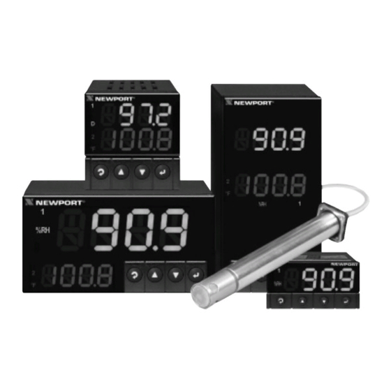
PART 1 INTRODUCTION 1.1 Description The iTH Series instruments monitor and control both temperature and relative humidity. • Used with an iTH probe the controller comes with dual displays. The top displays relative humidity and the bottom displays temperature. Relative Humidity can be toggled with Temperature readings (by pressing the b button) or Dewpoint readings (by pressing the c button). -
Page 7: Safety Considerations
1.2 Safety Considerations This device is marked with the international caution symbol. It is important to read this manual before installing or commissioning this device as it contains important information relating to Safety and EMC (Electromagnetic Compatibility). This instrument is a panel mount device protected in accordance with EN 61010-1:2001, electrical safety requirements for electrical equipment for measurement, control and laboratory. -
Page 8: Before You Begin
1.3 Before You Begin Inspecting Your Shipment: Remove the packing slip and verify that you have received everything listed. Inspect the container and equipment for signs of damage as soon as you receive the shipment. Note any evidence of rough handling in transit. -
Page 9: Part 2: Setup
PART 2 Refer to the Quick Start SETUP Guide for assembly and 2.1 Front Panel disassembly instructions. iTH-i32 1.00 [25.4] Relative Humidity Upper Display Temperature Lower Display iTH-i16D iTH-i8DH iTH-i8DV Figure 2.1 Front Panel Display The upper display may be RH, Temperature or Dewpoint readings depending on your Reading Configuration selections. -
Page 10: Rear Panel Connections
2.2 Rear Panel Connections The rear panel connections are shown in Figures 2.2 and 2.3. 8 7 6 5 4 3 2 1 Figure 2.2 Rear Panel Power and Output Connections Figure 2.3 Rear Panel Input Connections Table 2.2 Rear Panel Connector POWER AC/DC Power Connector: All models INPUT... -
Page 11: Electrical Installation
2.3 Electrical Installation 2.3.1 Power Connections Caution: Do not connect power to your device until you have completed all input and output connections. Failure to do so may result in injury! Connect the main power connections as shown in Figure 2.4. Use copper conductors only for power connections Figure 2.4 Main Power Connections... -
Page 12: Humidity And Temperature Probe
2.3.2 Humidity and Temperature Probe The figure below shows the wiring hookup for the temperature and humidity probe. METAL HOUSING IS CONNECTED TO SHIELD WIRE Choose one which gives the best signal integrity- 1) Connect Probe’s Shield to RTN if Probe Housing is not connected to Earth Ground. -
Page 13: Wiring Outputs - Wiring Hookup
2.3.3 Wiring Outputs This meter has two factory installed outputs. The SPDT Mechanical Relay, SPST Solid State Relay, Pulse and Analog Output Connection are shown below. Use copper conductors only for power connections Figure 2.6 a) Mechanical Relay and SSR b) Pulse and Analog Outputs Wiring Hookup Outputs Wiring Hookup... -
Page 14: Figure 2.8 Communication Output: A) Rs-232 Output - Wiring Hookup
This device may have a programmable communication output. The RS-232 and RS-485 Output Connection are shown below. Figure 2.8 a) RS-232 Output Wiring Hookup b) RS-485 Output Wiring Hookup This device may also have an excitation output. Excitation is not available if communication option is installed. -
Page 15: Dual Display Color Setup
2.3.4 Dual Display Color Setup The dual display option allows the user to change the color of the upper and lower displays. To change the color of the upper display, see Section 3.2.14 (Display Color section). To change the color of the lower display follow the instructions below: The unit should be removed from the panel and opened. -
Page 16: Part 3: Operation: Configuration Mode
PART 3 OPERATION: Configuration Mode 3.1 Introduction The instrument has two different modes of operation. The first, Run Mode, is used to display Temperature and Relative Humidity. The other mode, Menu Configuration Mode, is used to navigate through the menu options and configure the controller. -
Page 17: Menu Configuration
3.2 Menu Configuration It is required that you put the controller in the Standby Mode for any configuration change other than Setpoints & Alarms. Figure 3.1 Flow Chart for ID and Setpoints... -
Page 18: Id Number
3.2.1 ID Number TO ENABLE/DISABLE OR CHANGE ID CODE, SEE SECTION 3.2.12. If ID Code is Disabled or set as Default (0000) the menu will skip ID step to Setpoint Menu. If ID Code is set to Full Security Level and user attempts to enter the Main Menu, they will be prompted for an ID Code. -
Page 19: Setpoints
3.2.2 Set Points SETPOINT 1: Press a 1) Press a, if necessary until SP1 prompt appears. Press d 2) Display shows previous value of “Setpoint 1”. Press b & c 3) Press b and c to increase or decrease Setpoint 1 respectively. -
Page 20: Reading Configuration Menu
3.2.4 Reading Configuration is required that you put the controller in the Standby Mode for any configuration change other than Set Points & Alarms. Figure 3.3 Flow Chart for Reading Configuration Menu ENTER READING CONFIGURATION MENU: Press a 1) Press a , if necessary, until CNFG prompt appears. Press d 2) Display advances to RDG Reading Configuration Menu. -
Page 21: Alarm 1 Menu
3.2.5 Alarm 1 This unit is equipped with two physical outputs that can only be configured as follows: Alarm 1 & Alarm 2, Alarm 1 & Output 2, Output 1 & Alarm 2, Output 1 & Output 2, Analog Out 1 & Alarm 2, Analog Out 1 & Output 2. Analog Out available only if Analog Output Option board is factory installed. - Page 22 ALARM 1 ENABLE/DISABLE SUBMENU: Press b 5) Scroll though the available selection until ENBL displays to use Alarm 1. Press d 6) Display shows STRD stored message momentarily and then advances to ABSo only if it was changed, otherwise press a to advance to ABSo Alarm 1 Absolute/Deviation Submenu.
- Page 23 CONTACT CLOSURE SUBMENU: 11) Display flashes previous selection. Press b to N.ç. Normally Press d Closed or N.o. Normally Open. Press d 12) Display shows STRD stored message momentarily (only if it was changed) and then advances to AçTV . Normally Open: If this feature is selected, then the relay is "energized"...
- Page 24 ALARM ENABLE/DISABLE AT POWER ON: Press d 15) Display flashes previous selection. Press b to ENBL enable or DSBL disable. Press d 16) Display shows STRD stored message. momentarily (only if it was changed) and then advances to ALR.L . If Alarm at Power On is enabled, the alarm will be active when an alarm condition occurs.
-
Page 25: Analog Output (Retransmission) Menu
3.2.6 Analog Output (Retransmission) Analog Output works only for Humidity Readings and can be configured as Retransmission or Control outputs. This section will explain Retransmission Output. This unit is equipped with two physical outputs that can only be configured as follows: Alarm 1 &... - Page 26 ANALOG OUTPUT ENABLE/DISABLE SUBMENU: Press b 5) Scroll though the available selection until ENBL displays to use Analog Output Retransmission (output proportional to the input signal). Press d 6) Display shows STRD stored message momentarily and then advances to CURR or VoLT Submenu only if it was changed, otherwise press a to advance to CURR or VoLT Current/Voltage Submenu.
- Page 27 Accuracy of Analog Output board is +/-1% of FS (Full Scale) when following conditions are satisfied: 1. The input is not scaled below 1% of Input FS (10 mV @ 1 V or 0.2 mA @ 20 mA input ranges). 2.
-
Page 28: Alarm 2 Menu
3.2.7 Alarm 2 This unit is equipped with two physical outputs that can only be configured as follows: Alarm 1 & Alarm 2, Alarm 1 & Output 2, Output 1 & Alarm 2, Output 1 & Output 2, Analog Out 1 & Alarm 2, Analog Out 1 & Output 2. Analog Out available only if Analog Output Option board is factory installed. -
Page 29: Loop Break Time Menu/Field Calibration
3.2.8 Loop Break Time It is required that you put the controller in the Standby Mode for any configuration change other than Set Points & Alarms. Figure 3.7 Flow Chart for Loop Break Time ENTER LOOP BREAK TIME MENU: 1) Press a , if necessary, until CNFG prompt appears. Press a Press d 2) Display advances to RDG Reading Configuration Menu. - Page 30 READING ADJUST SUBMENU: 10) Display flashes 1 st digit of previous reading adjust value. Press d Press b & c 11) Press b and c buttons to enter a new Reading Adjust value (-1999 to 9999). Press d 12) Display shows STRD stored message momentarily and then advances to SP.DV Setpoint Deviation Menu.
-
Page 31: Figure 3.8 Flow Chart For Output 1
3.2.9 Output 1 Alarm 1 and Output 1 or Analog Output (Retransmission) share the same contacts on the rear panel connector. If Alarm 1 or Analog Output (Retransmission) is Enabled, Output 1 is automatically Disabled. is required that you put the controller in the Standby Mode for any configuration change other than Set Points &... -
Page 32: Output 1 Menu
ENTER OUTPUT 1 MENU: Press a 1) Press a , if necessary, until CNFG prompt appears. Press d 2) Display advances to RDG Reading Configuration Menu. Press a 3) Press a , if necessary, until Display advances to OUT1 Output 1 Menu. - Page 33 MAXIMUM/PERCENT HIGH SUBMENU: Specify in percent, the maximum value (99) for control output. If the output is analog proportional (Current or Voltage), then the maximum voltage or current, in percent, is specified. If the output is time proportional (Relay, SSR, or Pulse), then the maximum duty-cycle, in percent, is specified.
- Page 34 ACTION TYPE SUBMENU: The error that results from the measurement of the Process Variable may be positive or negative since it may be greater or smaller than the Setpoint. If a positive error should cause the instrument output to increase (i.e. cooling), it would be called Direct Acting.
- Page 35 If Anti Integral (Anti Windup) Submenu “Enabled”, this feature allows the error term outside the proportional band to be calculated and accumulated for integration. This may be an important feature in applications where fast response time is desirable. START AUTO TUNE PID: Press d 27) Display flashes ENBL or DSBL .
- Page 36 RESET SETUP SUBMENU: Press d digit of the previous I REST Reset value. 33) Display flashes 1 Press b & c 34) Press b and c buttons to enter a new “Reset” value. Press d 35) Display shows STRD stored message momentarily and then advances to RATE only, if it was changed, otherwise press a to advance to RATE Rate Setup Submenu.
- Page 37 DAMPING FACTOR SUBMENU: Press d 42) Display flashes the previous “Damping Factor” selection. 43) Scroll through the available selections: 0000 , 0001 , 0002 , Press b 0003 , 0004 , 0005 , 0006 , 0007 . Press d 44) Display flashes STRD stored message and then advances to OUT2 only, if it was changed, otherwise press a to advance to OUT2 Output 2 Menu.
-
Page 38: Output 2 Menu
3.2.10 Output 2 Output 2 and Alarm 2 share the same contacts on the rear panel connector. If Alarm 2 is Enabled, Output 2 is automatically Disabled. It is required that you put the controller in the Standby Mode for any configuration change other than Set Points &... - Page 39 ACTION TYPE SUBMENU: The error that results from the measurement of the Process Variable may be positive or negative since it may be greater or smaller than the Setpoint. If a positive error should cause the instrument output to increase (i.e. cooling), it would be called Direct Acting.
-
Page 40: Ramp And Soak Menu
3.2.11 Ramp & Soak Alarm must be DISABLED if Ramp is ENABLED. is required that you put the controller in the Standby Mode for any configuration change other than Set Points & Alarms. If DRRh is selected in the Reading Configuration Menu the unit will ramp only on humidity, but if °F.°C is selected, both humidity and temperature will ramp to Setpoint. - Page 41 SOAK ENABLE/DISABLE SUBMENU: Press d 7) Display flashes ENBL or DSBL . Press b 8) Scroll through the available selections: “Enable” or “Disable”. Press d 9) Display shows STRD stored message momentarily and then advances to “Ramp Value” Submenu. Ramp & Soak provides users with the flexibility to slowly bring the Process Variable (PV) to the desired setpoint.
-
Page 42: Id Code Menu
3.2.12 ID CODE Figure 3.11 Flow Chart for ID Code ENTER ID CODE MENU: 1) Press a , if necessary, until CNFG prompt appears. Press a Press d 2) Display advances to RDG Reading Configuration Menu. Press a 3) Press a , if necessary, until Display advances to ID ID Code Menu. - Page 43 ENTERING OR CHANGING YOUR (DEFAULT) ID CODE: Enter ID menu (Repeat steps from 1 to 3). Press d 10) Display advances to CH.ID Change ID Code Submenu. Press d 11) Display shows 0000 message with flashing 1 digit. If you want to change your default “ID Code” you can do it now, otherwise press a and menu will skip to FULL Full Security Submenu.
-
Page 44: Communication (Options) Menu
3.2.13 COMMUNICATION OPTION Purchasing the controller with Serial Communications permits an instrument to be configured or monitored from an IBM PC compatible computer using software available from the website or on the CD-ROM enclosed with your shipment. For complete instructions on the use of the Communications Option, refer to the Serial Communications Reference Manual. -
Page 45: Table 3.2 Command Letters And Suffix For Ith
The following table are the exceptions to the Serial Communication Manual’s Table 5.3 Table 3.2 Command Letters and Suffix for iTH Command Command Function Command # Of Default Index Bytes Characters Value Send RH Reading Send Temperature Reading Send Dewpoint Reading ENTER COMMUNICATION OPTION MENU: Press a 1) Press a , if necessary, until CNFG prompt appears. - Page 46 STOP BIT SUBMENU: Press d 15) Display flashes previous selection for “Stop Bit”. Press b 16) Scroll through the available selections: 1-BIT , 2-BIT . 17) Display shows STRD stored message momentarily and then Press d advances to BUS.F only, if it was changed, otherwise press a to advance to BUS.F Bus Format Submenu.
- Page 47 Press d 25) Display flashes previous selection for “Echo”. Press b 26) Scroll through the available selections: NO, YES. Press d 27) Display flashes STRD stored message momentarily and then advances to STND only if it was changed, otherwise press a to advance to STND Communication Standard Submenu.
- Page 48 DATA FORMAT SUBMENU: Preformatted data can be sent automatically or upon request from the controller. Use the Data Format Submenus to determine what data will be sent in this preformatted data string. Refer to the iSeries Communications Manual for more information about the data format.
- Page 49 TEMPERATURE UNIT SUBMENU: Includes a byte in the data string to indicate whether reading is in Celsius or Fahrenheit. Press d 50) Display flashes previous selection for UNIT . Press b 51) Scroll through the available selections: NO, YES. Press d 52) Display shows STRD stored message momentarily and then advances to ADDR only, if it was changed, otherwise press a to advance to ADDR Address Setup Submenu.
-
Page 50: Display Color Selection Menu
3.2.14 DISPLAY COLOR SELECTION This submenu allows the user to select the color of the upper display. Figure 3.13 Flow Chart for Display Color Selection ENTER DISPLAY COLOR SELECTION MENU: Press a 1) Press a , if necessary, until CNFG prompt appears. Press d 2) Display advances to RDG Reading Configuration Menu. - Page 51 ALARM 2 DISPLAY COLOR SUBMENU: Press d 11) Display flashes previous selection for “Alarm 2 Color Display”. Press b 12) Scroll through the available selections: GRN , RED or AMBR . Press d 13) Display shows STRD stored message momentarily and then momentarily shows the software version number, followed by RST Reset, and then proceeds to the Run Mode.
- Page 52 Example 3: Output 1 = Analog Output (Alarm 1 disabled), Setpoint 1 = 300, Output 2 = Relay, Setpoint 2 = 200 Alarm 1 & 2 Setup: Deviation, Band, “ALR.H” = 10 Color Display Setup: “N.CLR” = Green, “1.CLR” = Amber, “2.CLR” = Red Display Colors change sequences: GREEN •...
-
Page 53: Part 4: Specifications
PART 4 SPECIFICATIONS Display SENSOR SPECIFICATIONS 4-digit, 9-segment LED • 10.2mm (0.40"): i32, i16D, i8DV Relative Humidity (RH) Accuracy/Range: ±2% for 10 to 90% RH • 10.2mm (0.40”) & 21mm (0.83”): i8DH ±3% for 0 to 10%RH and 90 to 100%RH red, green and amber programmable Non-linearity: ±3% colors for process variable, set point... - Page 54 CONTROL OUTPUT 1 & 2 ALARM 1 & 2 (programmable): Relay Type 250 Vac or 30 Vdc @ 3 A Same as Output 1 & 2 (Resistive Load); configurable for Operation on/off, PID and Ramp and Soak High/low, above/below, band, Output 1: SPDT type, can be latch/unlatch, normally open/normally configured as Alarm 1 output...
- Page 55 GENERAL Protection Line Voltage/Power NEMA-4x/Type 4/IP65 front bezel: i32, i16D 90-240 Vac +/-10%, 50-400 Hz* NEMA-1/Type 1 front bezel: i8DH, i8DV 110-375 Vdc, equivalent voltage Dimensions 4 W, power for i32 Models i/8 Series: 5 W, power for i8DV, i8DH, i16D Models 48 H x 96 W x 127 mm D * No CE compliance above 60 Hz (1.89 x 3.78 x 5")
-
Page 56: Part 5: Factory Preset Values
PART 5 FACTORY PRESET VALUES Table 5.1 Factory preset value MENU ITEMS FACTORY PRESET VALUES NOTES Set Point 1 (SP1) 000.0 Set Point 2 (SP2) 000.0 Reading Configuration (RDG): Sensor (SENS) Decimal Point FFF.F not menu selectable Temperature unit (tEMP) °F Filter value (FLtR) 0004... - Page 57 MENU ITEMS FACTORY PRESET VALUES NOTES Ramp & Soak (RAMP) : Ramp (RAMP) Disable (dSbL) Soak (SOAK) Disable (dSbL) Ramp Value (RAMP) 00:00 Soak Value (SOAK) 00:00 ID : ID Value 0000 Full ID (FULL) Disable (dSbL) Set Point ID (Id.SP) Disable (dSbL) Communication Parameters: Baud Rate (BAUd)
-
Page 58: Ce Approval Information
PART 6 CE APPROVALS INFORMATION This product conforms to the EMC directive 89/336/EEC amended by 93/68/EEC, and with the European Low Voltage Directive 72/23/EEC. Electrical Safety EN61010-1:2001 Safety requirements for electrical equipment for measurement, control and laboratory. Double Insulation Pollution Degree 2 Dielectric withstand Test per 1 min •... - Page 59 Warranty/Disclaimer NEWPORT Electronics, Inc. warrants this unit to be free of defects in materials and workmanship for a period of one (1) year from the date of purchase. In addition to NEWPORT’s standard warranty period, NEWPORT Electronics will extend the warranty period for four (4) additional years if the warranty card enclosed with each instrument is returned to NEWPORT.
- Page 60 Newport Electronics GmbH Daimlerstrasse 26 • D-75392 Deckenpfronn • Germany TEL: 49 7056 9398-0 • FAX: 49 7056 9398-29 Toll Free: 0800 / 6397678 • www.newport.de • e-mail: sales@newport.de Newport Electronique S.A.R.L. 11, rue Jacques Cartier • 78280 Guyancourt • France TEL: +33 1 61 37 29 00 •...
Need help?
Do you have a question about the i Series and is the answer not in the manual?
Questions and answers