Festo CPX-FB33 Manual
Cpx bus node
Hide thumbs
Also See for CPX-FB33:
- Electronics description (134 pages) ,
- Manual (110 pages) ,
- Operating instructions manual (40 pages)

Subscribe to Our Youtube Channel
Related Manuals for Festo CPX-FB33


Summary of Contents for Festo CPX-FB33
- Page 1 Terminal CPX Bus node CPX-(M)-FB33/34/35 Description Network protocol PROFINET IO 548760 en 1407c [8032733]...
- Page 3 ........548760 © (Festo AG & Co. KG, 73726 Esslingen, Germany, 2014) Internet: www.festo.com E-mail: service_international@festo.com...
- Page 4 Contents and general safety instructions ® ® ® ® ® ® ® PROFIBUS , PROFIenergy , PROFINET IO , PROFIsafe , SIMATIC , TORX , TÜV ® are registered trademarks of the respective trademark owners in certain countries. Festo P.BE-CPX-PNIO-EN en 1407c English...
-
Page 5: Table Of Contents
..1-20 1.6.3 Network interface of the CPX-FB33 ......1-24 1.6.4... - Page 6 ..... 2-56 2.8.4 Parameterisation through the Festo Maintenance Tool ..2-56 2.8.5...
- Page 7 ......Network-specific technical data bus node CPX-FB33, CPX-M-FB34 and CPX-M-FB35 ....
- Page 8 Contents and general safety instructions Festo P.BE-CPX-PNIO-EN en 1407c English...
-
Page 9: Intended Use
Contents and general safety instructions Intended use The bus nodes documented in this description, CPX-FB33, CPX-M-FB34 and CPX-M-FB35, are intended only for use as participants (I/O device) on the Industrial Ethernet system PROFINET IO. The bus nodes can be used in three different operating modes: –... - Page 10 Through the use of PELV circuits, protection against electric shock (protection against direct and indirect contact) is en- sured in accordance with IEC 60204-1. Observe the measures in section 2.11 and section 3.1 when implementing an emergency off or emergency stop function. VIII Festo P.BE-CPX-PNIO-EN en 1407c English...
-
Page 11: Target Group
(PLC) and field- bus systems. Service Please consult your local Festo repair service if you have any technical problems. Festo P.BE-CPX-PNIO-EN en 1407c English... -
Page 12: Notes Regarding This Description
650 nm wavelength, suitable – PROFINET installation for POF fibre-optic cable, guidelines AIDA-compliant, – IEC 61158 corresponding to IEC 61754-24 – IEC 61784 – IEC 61918. Additional information: www.profinet.com Tab. 0/1: Bus node for PROFINET – overview Festo P.BE-CPX-PNIO-EN en 1407c English... - Page 13 An overview of the structure of the CPX terminal User Docu- mentation can be found in the CPX system description (P.BE-CPX-SYS...). Product-specific information about the control system (IPC, PLC or I/O controller) can be found in the manufacturer’s product documentation accompanying the product. Festo P.BE-CPX-PNIO-EN en 1407c English...
-
Page 14: Important User Instructions
... means that failure to observe this instruction may result in material damage. In addition, the following pictogram marks passages in the text which describe activities with electrostatically sensitive devices: Electrostatically sensitive devices: Incorrect handling may cause damage to components. Festo P.BE-CPX-PNIO-EN en 1407c English... - Page 15 Recommendations, tips and references to other information sources. Accessories: Information about necessary or useful accessories for the product from Festo. Environment: Information on the environmentally friendly use of Festo products. Text designations Bullet points denote activities that may be carried out in • any sequence.
- Page 16 Installation system comprising CPX modules with or without valve terminal (pneumatics modules) dual in-line DIL switches Miniature switch that consists of several switching elements, with which, for example, basic settings can be made Tab. 0/2: Specific terms and abbreviations – part 1 Festo P.BE-CPX-PNIO-EN en 1407c English...
- Page 17 – stand-alone system controller (PLC, Stand Alone operating mode) – system controller (PLC, Remote Controller operating mode) – fieldbus slave (Remote I/O operating mode) Festo Maintenance Tool (CPX-FMT); configuration and programming software for CPX modules for commissioning and service purposes Fibre-optic cable (FOC, fibre optics) Fibre-optic cable “Fast Start-up”, also designated “Prioritized Start-up”...
- Page 18 Electromagnetic valves with shared power supply, air supply and control; the valves and pneumatic components on the right side of the pneumatic interface together form the valve terminal pneumatics Tab. 0/4: Specific terms and abbreviations – part 3 Festo P.BE-CPX-PNIO-EN en 1407c English...
-
Page 19: Installation
Installation Chapter 1 Installation Festo P.BE-CPX-PNIO-EN en 1407c English... - Page 20 ..1-20 1.6.3 Network interface of the CPX-FB33 ......1-24 1.6.4...
-
Page 21: General Instructions On Installation
Observe the handling specifications for electrostatically • sensitive devices. By doing so, you avoid malfunctions of and damage to the electronics. Information about mounting of the CPX terminal can be found in the CPX system description (P.BE-CPX-SYS-..). Festo P.BE-CPX-PNIO-EN en 1407c English... -
Page 22: Electrical Connection And Display Components
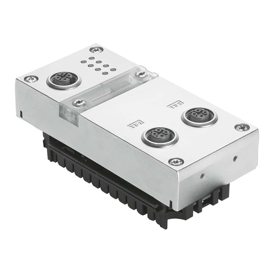
CPX-M-FB34: 2 x RJ45 socket, code (“Rev ...”) Push-pull, AIDA-conforming CPX-M-FB35: 2 x SCRJ-Buchse, Push-pull, AIDA-conforming Fig. 1/1: Connection and display components on the bus node for PROFINET Note Use cover caps to seal unused connections ( Section 1.7). Festo P.BE-CPX-PNIO-EN en 1407c English... -
Page 23: Mounting And Dismounting Of The Bus Node
2. Push the bus node carefully and without tilting into the interlinking block up to the stop ( Fig. 1/2). 3. Turn the screws into the existing thread. 4. Tighten the screws in diagonally opposite sequence. Tightening torque: 0.9 ... 1.1 Nm. Festo P.BE-CPX-PNIO-EN en 1407c English... - Page 24 Bus node (example CPX-FB33) Interlinking block Screws Fig. 1/2: Mounting/dismounting the bus node Dismounting Dismount the bus node as follows: 1. Unscrew screws. 2. Pull the bus node without tilting out of the interlinking block. Festo P.BE-CPX-PNIO-EN en 1407c English...
-
Page 25: Setting The Dil Switches, Use Of The Memory Card
Switch off the power supply before removing the cover. • Make sure that the seal is seated correctly when attach- • ing the cover! Tighten the two fastening screws at first by hand and • then with max. 0.4 Nm. Festo P.BE-CPX-PNIO-EN en 1407c English... -
Page 26: Settingthe Dil Switches
(only in remote I/O operating mode); data field size (only in remote controller operating mode) Memory card (see section 1.4.3, 1.5 as well as 2.6.3 and 2.8.1) Fig. 1/3: Settings of the DIL switches in the bus node Festo P.BE-CPX-PNIO-EN en 1407c English... - Page 27 Further explanations of the bus node operating mode can be found in section B.1: – remote I/O operating mode Section B.1.1 – remote controller operating mode Section B.1.2 – additional function “Fast Start-up” (FSU) Section B.1.3. Festo P.BE-CPX-PNIO-EN en 1407c English...
- Page 28 Diagnostics mode status bits occupy 1 byte of address space (8 I bits) Diagnostics mode I/O diagnostics interface occupies 4 bytes of address space (16 I and 16 O bits) From Revision 21 Tab. 1/2: Setting the diagnostics mode with DIL switch 1-10 Festo P.BE-CPX-PNIO-EN en 1407c English...
- Page 29 I/O bits are available for module communica- tion without restriction. Set the DIL switch to the factory setting for this pur- pose (see Tab. 1/2). Parameterise the diagnostics mode via the hardware configuration. 1-11 Festo P.BE-CPX-PNIO-EN en 1407c English...
- Page 30 1) CPX Rev 18, CPX-FO Rev 18, CPX FSU Rev 18 or CPX-FO FSU Rev 18 for bus node with CPX revision code Rev 12 … Rev 18 Tab. 1/3: Bus node selection (station symbol or field device group) dependent on operating mode, diagnostics mode and additional function FSU 1-12 Festo P.BE-CPX-PNIO-EN en 1407c English...
- Page 31 Maximum data field size: DIL 2.2: 16 bytes I/16 bytes O DIL 2.1: Reserved for future extensions DIL 2.2: DIL 2.1: Reserved for future extensions DIL 2.2: Tab. 1/4: Setting the data field size with DIL switch 1-13 Festo P.BE-CPX-PNIO-EN en 1407c English...
-
Page 32: Using The Memory Card
Disconnect the power supply before you insert or • remove the memory card. Replacing The memory card is under a cover (see Fig. 1/1). You need a the memory card screwdriver in order to remove or attach this cover. 1-14 Festo P.BE-CPX-PNIO-EN en 1407c English... -
Page 33: Replacement Of The Bus Node
Inserting or removing the memory card while the power supply is switched on can result in malfunctions of or dam- age to the memory card. Disconnect the power supply before you insert or re- • move the memory card. 1-15 Festo P.BE-CPX-PNIO-EN en 1407c English... - Page 34 4. Start your configuration and programming software (e.g. Siemens STEP 7). 5. Perform a new configuration (hardware configuration, in STEP 7 using HW Config). 6. The controller loads all required data into the bus node. 1-16 Festo P.BE-CPX-PNIO-EN en 1407c English...
-
Page 35: Connecting To The Network
– virtual LAN (VLAN) – virtual private network (VPN) – security at physical access level (Port Security). For further information, please refer to the guidelines and standards for security in information technology, e.g. IEC 62443, ISO/IEC 27001. 1-17 Festo P.BE-CPX-PNIO-EN en 1407c English... - Page 36 1. Installation An access password protects only against accidental changes. 1-18 Festo P.BE-CPX-PNIO-EN en 1407c English...
- Page 37 Note Make sure that any intermediate switches and routers sup- port the PROFINET function “Fast Start-up” (FSU) when you use this additional function. Further information on FSU can be found in section B.1.3. 1-19 Festo P.BE-CPX-PNIO-EN en 1407c English...
-
Page 38: Overview Of Connections, Network Connectors And Cables
IEC 60603, IEC 61076-3 CPX-M-FB35 2 x SCRJ sockets, push-pull, AIDA-compli- Plug FBS-SCRJ-PP-GS ant, corresponding to IEC 61754-24, 650 nm wavelength, suitable for POF fibre-optic cable www.festo.com/catalogue/ Tab. 1/5: Overview of connection technology and network plugs 1-20 Festo P.BE-CPX-PNIO-EN en 1407c English... - Page 39 Crossover detection is not available in the remote I/O operat- ing mode with additional function “Fast start-up” (FSU): Use only suitable lines. • Observe the following note regarding pin allocation of • port TP2. 1-21 Festo P.BE-CPX-PNIO-EN en 1407c English...
- Page 40 Switch port, e.g. of the PLC Patch cable (“crossover” pin allocation) Terminal port of an I/O device Fig. 1/4: Wiring of the I/O devices for “Fast start-up” with deactivated “crossover” de- tection or “autonegotiation” (configuration example) 1-22 Festo P.BE-CPX-PNIO-EN en 1407c English...
- Page 41 1) Length corresponding to specification for PROFINET networks (PROFINET Installation Guide) based on ISO/IEC 11801, ANSI/TIA/EIA-568 (see also section 1.6.1) www.profinet.com, www.profibus.com/download/ Tab. 1/6: Overview of line specification (in combination with Festo bus node and Festo network plug) 1-23 Festo P.BE-CPX-PNIO-EN en 1407c English...
-
Page 42: Network Interface Of The Cpx-Fb33
Also observe the corresponding regulations in EN 60204 Part 1. 1.6.3 Network interface of the CPX-FB33 There are two 4-pin, D-coded M12 sockets on the CPX-FB33 for the network connection. Socket Signal... -
Page 43: Network Interface Of The Cpx-M-Fb34
Pin allocation of the network interfaces of the CPX-M-FB34 (RJ45) Connection with plug from Festo Connect the CPX terminal to the network with a Festo plug FBS-RJ45-PP-GS. The plug is designed for Ethernet cable with cable diameter of 5 ..8 mm. -
Page 44: Network Interface Of The Cpx-M-Fb35
Pin allocation of the network interfaces of the CPX-M-FB35 (SCRJ) Connection with plug from Festo Connect the CPX terminal to the network with a Festo plug, FBS-SCRJ-PP-GS. The plug is designed for POF fibre-optic cable with cable diameter of 6.5 ... 9.5 mm. -
Page 45: Ensuring The Protection Class
Network connection (SCRJ) Service interface Connecting cable KV-M12-M12-… ISK-M12 1) Connecting cable for the operator unit (CPX-MMI) 2) Included in scope of delivery Tab. 1/10: Connection technology and cover caps for degree of protection IP65/IP67 (examples) 1-27 Festo P.BE-CPX-PNIO-EN en 1407c English... -
Page 46: Power Supply
Note Observe the notes on installation and power supply as well as potential equalisation (earthing measures) in the CPX system description (P.BE-CPX-SYS-... Electrical connec- tion) and in the descriptions for the valve terminal used. 1-28 Festo P.BE-CPX-PNIO-EN en 1407c English... - Page 47 “Pin allocation, power supply” (CPX-PIN-BEL- … Load rating per pin). Observe the measures in sections 2.11 and 3.1 when imple- menting an EMERGENCY-OFF function. 1-29 Festo P.BE-CPX-PNIO-EN en 1407c English...
- Page 48 1. Installation 1-30 Festo P.BE-CPX-PNIO-EN en 1407c English...
-
Page 49: Commissioning
Commissioning Chapter 2 Commissioning Festo P.BE-CPX-PNIO-EN en 1407c English... - Page 50 ..... 2-56 2.8.4 Parameterisation through the Festo Maintenance Tool ..2-56 2.8.5...
-
Page 51: General Instructions
1. Switch on the operating voltage supply of all bus stations (I/O devices). 2. Switch on the operating voltage supply for the controller. Festo P.BE-CPX-PNIO-EN en 1407c English... - Page 52 (see sec- tion 2.6). Parameterisation A CPX terminal in the PROFINET network can be paramet- erised through the control system (PLC/IPC), an operator unit (CPX-MMI) or the Festo Maintenance Tool (CPX-FMT) (see sec- tion 2.8). Festo P.BE-CPX-PNIO-EN en 1407c English...
-
Page 53: Address Assignment
CPX terminal. Tab. 2/8 provides help with this. Use the configuration documents, the operator unit (CPX- MMI) or the Festo Maintenance Tool (CPX-FMT) to determine address assignment or terminal configuration. In the operator unit, the individual modules of the CPX ter- minal are displayed with the respective module identifiers. - Page 54 (see Tab. 2/1). In the Remote I/O (RIO) operating mode, the identifiers of the bus node (including diagnostics mode), the CPX mod- ules and, if present, the pneumatics modules are configured (see Tab. 2/2). Festo P.BE-CPX-PNIO-EN en 1407c English...
- Page 55 (independent of the diagnostics mode) Diagnostics mode status bits occupies 16 I or 2 bytes of address space (8 I or 8 bits remain unused) Tab. 2/2: Address assignment of the bus nodes for the Remote I/O operating mode Festo P.BE-CPX-PNIO-EN en 1407c English...
- Page 56 4-off modules (CPX-4DE and CPX-4DA) occupy 8 I or 8 O or 1 byte of address space (4 I/O or 8 bits of address space remain unused) Tab. 2/3: Example of address assignment of electric CPX modules (overview; bus node in Remote I/O operating mode) – Part 1 Festo P.BE-CPX-PNIO-EN en 1407c English...
- Page 57 Address space assignment dependent on the string allocation (4 byte I or 4 byte O per string) Tab. 2/4: Example of address assignment of electric CPX modules (overview; bus node in Remote I/O operating mode) – Part 2 Festo P.BE-CPX-PNIO-EN en 1407c English...
- Page 58 2 byte I or 16 inputs. Pneumatic modules of type VPPM each occupy 4 bytes of address space, i.e. 2 bytes I / 2 bytes O or 16 in- puts and 16 outputs. 2-10 Festo P.BE-CPX-PNIO-EN en 1407c English...
- Page 59 CPA, MPA and VTSA/VTSA-F or ISO) contain the address as- signment within the pneumatic modules. Information about pneumatic interfaces and pneumatic mod- ules can be found in the descriptions of the input/output modules P.BE-CPX-EA-… and P.BE-CPX-AX-... 2-11 Festo P.BE-CPX-PNIO-EN en 1407c English...
- Page 60 Module identifier in the operator unit or in the hardware configuration of the programming software 4-off modules MPA2 always occupy 8 O (1 byte) of address space (4 O or 8 bits remain unused) Tab. 2/5: Overview of CPX pneumatic interfaces and pneumatic modules (part 1) 2-12 Festo P.BE-CPX-PNIO-EN en 1407c English...
- Page 61 Observe the sequence of the modules as part of addressing or in I/O mapping (see Tab. 2/9) MPAF-P is also called “end plate” with pressure sensor or pressure sensor plate Tab. 2/6: Overview of CPX pneumatic interfaces and pneumatic modules (part 2) 2-13 Festo P.BE-CPX-PNIO-EN en 1407c English...
- Page 62 Module identifier in the operator unit or in the hardware configuration of the programming software Setting with DIL switch in the pneumatic interface Display text (module identifier) dependent on the version of the operator unit Tab. 2/7: Overview of CPX pneumatic interfaces and pneumatic modules (part 3) 2-14 Festo P.BE-CPX-PNIO-EN en 1407c English...
- Page 63 ) 4-off modules CPX-4DE and CPX-4DA as well as MPA2 pneumatic modules generally occupy 8 inputs or outputs (1 byte; available address space remains partially unused) Tab. 2/8: Determination of the assigned address space (total of inputs and outputs) 2-15 Festo P.BE-CPX-PNIO-EN en 1407c English...
-
Page 64: Addressing
8 bits or 1 byte of address space, but do not use this space completely. – The I/Os of different module types are assigned separ- ately from each other. Observe the sequence of address- ing: see Tab. 2/9. 2-16 Festo P.BE-CPX-PNIO-EN en 1407c English... - Page 65 Move the modules originally configured in this address range into another area. Configuration of these modules must be repeated, if necessary (see also section 2.7 regarding con- figuration with PROFINET configuration and programming software, e.g. Siemens SIMATIC STEP 7). 2-17 Festo P.BE-CPX-PNIO-EN en 1407c English...
-
Page 66: Address Assignment And Addressing After Expansion Or Conversion
– or vice versa (see Pneumatics description). – Additional interlinking blocks (CPA) or manifold blocks (Midi/Maxi) are inserted between existing ones. – The diagnostics mode (status bits or the I/O diagnostics interface) is activated/deactivated. 2-18 Festo P.BE-CPX-PNIO-EN en 1407c English... -
Page 67: Instructions For Commissioning With Siemens Simatic Step 7
Please take information on other variants from the documents on your controller and control software. In case of technical problems, please first contact the respect- ive manufacturer. In cases of doubt, your local Festo Service is happy to help you further. 2-19... - Page 68 (e.g. actuators) do not perform any unexpected or uncontrollable movements. If necessary, disconnect the load power supply and com- pressed air supply. See also section 2.11: Check list for commissioning the CPX terminal. 2-20 Festo P.BE-CPX-PNIO-EN en 1407c English...
-
Page 69: Preparing For Commissioning
File download Download the current GSDML file for PROFINET to your con- troller system: Click on “File and language versions”. • Click on the filenames: • “GSDML-V…-Festo-CPX-…zip”. Save the file on your control system. • 2-21 Festo P.BE-CPX-PNIO-EN en 1407c English... - Page 70 GSDML versions. Observe the notes in the “Read Me” file as well as the • instructions in section 2.5.2 before installing the GSDML file. Installation of the GSDML file is explained in section 2.5.5. • 2-22 Festo P.BE-CPX-PNIO-EN en 1407c English...
-
Page 71: Select Gsdml File (Compatibility Table)
Tab. 2/10: Compatibility of GSDML file, bus nodes and controller The current GSDML file for CPX terminals can be found in the Festo Support Portal: www.festo.com/sp Section 2.5.1. Consult your local Festo repair service if you have any ques- tions or technical problems. 2-23 Festo P.BE-CPX-PNIO-EN en 1407c English... -
Page 72: Setting Up Automation Project
4. Select the controller used (PLC/Master): Insert > Station > ... (e.g. SIMATIC 300 Station). 5. Open the project by clicking on the plus symbol (on the left next to the project symbol and the project name). 2-24 Festo P.BE-CPX-PNIO-EN en 1407c English... -
Page 73: Setting Up The Controller System (Plc/Master)
The sub-window symbolises the rack rail (profile rail) of your control system. You compile the individual elements of your controller in this child window and thus form the basis for your PROFINET automation system. 2-25 Festo P.BE-CPX-PNIO-EN en 1407c English... - Page 74 (Rail) 6. Insert your CPU and a PROFINET-IO system into the hard- ware configuration: Drag the corresponding catalogue elements (symbols) into the Rack Rail window ( 3 or 4 in Fig. 2/1). 2-26 Festo P.BE-CPX-PNIO-EN en 1407c English...
-
Page 75: Install Gsdml File
Options > Update Catalog. All available CPX modules appear in the hardware cata- logue under PROFINET IO > Additional Field Devices > Valves > Festo CPX Terminal. You can start the selection and configuration of your mod- ules (see section 2.6). -
Page 76: Basic Hardware Configuration
CPX terminal flash for unique identification. You can assign a device name to the CPX terminal in the next step. This device name is also stored on the memory card of the bus node (if inserted). 2-28 Festo P.BE-CPX-PNIO-EN en 1407c English... - Page 77 2. Commissioning 5. Enter a device name in the “Device name” field (e.g. CPX or CPX-01) and confirm the entry by clicking on “Assign name”. 2-29 Festo P.BE-CPX-PNIO-EN en 1407c English...
-
Page 78: Select Cpx Terminal (Station Selection)
Fig. 2/2: Station selection using Siemens STEP 7 - HW Config 2. If the hardware catalogue is not opened: Click on the catalogue symbol ( 1 in Fig. 2/2) or use the keyboard combination [Ctrl] + [K]. The hardware catalogue is displayed. 2-30 Festo P.BE-CPX-PNIO-EN en 1407c English... - Page 79 “\PROFINET-IO\Additional Field Devices\Valves\Festo CPX-Terminal” (English language version of the software) Note If the folder “Valves\Festo CPX-Terminal” is not displayed (see Fig. 2/3), repeat installation of the device master file (GSDML, see section 2.5.5). Fig. 2/3: Station selection – selection of the station symbol (Festo CPX terminals) 4.
- Page 80 2. Commissioning Example: With use of a bus node CPX-FB33 – with Rev 14 – in the Remote I/O operating mode, without the addition- al function “Fast Start-up”, open the station symbol CPX ( 1 in Tab. 2/11). Station symbol 1...
-
Page 81: Assign "Device Name
CPX terminal (see section 2.6.1), you can skip the steps 6. and 7.. 6. Double click on the symbol of the CPX terminal 3. Assign device name The “Properties – CPX” window is displayed (see Fig. 2/4). 2-33 Festo P.BE-CPX-PNIO-EN en 1407c English... - Page 82 7. Enter a unique device name for the CPX terminal in the “Device Name” field ( 1 in Fig. 2/4) or “Name” ( 1 in Fig. 2/5), e.g. CPX-01, Station-xy or an application-specific designation. 2-34 Festo P.BE-CPX-PNIO-EN en 1407c English...
-
Page 83: Set Up Prioritized Start-Up ("Fast Start-Up")
In the next steps, you can set up the “Prioritized Start-up” additional function. The additional function “Prioritized Start-up” is also desig- nated “Fast Start-up” (FSU). If you do not want to use this additional function, you can omit steps 8. to 20.. 2-35 Festo P.BE-CPX-PNIO-EN en 1407c English... - Page 84 8. Place a check in front of “Prioritized Startup” 2 in the Activate “Fast Start-up” window “Properties – CPX” (see Fig. 2/5). 9. Select the tab “IO Cycle” (1 in Fig. 2/6). Fig. 2/6: “Fast-Start-up” settings – adaptation of the I/O cycle time (update time) 2-36 Festo P.BE-CPX-PNIO-EN en 1407c English...
- Page 85 (see Fig. 2/2 or 2 in Fig. 2/11). 14. Double click in the configuration line of the connection (port) “X1 TP1”. The window “Properties – CPX FSU Port 1” (X1 TP1) is displayed (see Fig. 2/7). 2-37 Festo P.BE-CPX-PNIO-EN en 1407c English...
- Page 86 Fig. 2/7: “Fast-Start-up” settings – deactivation of the crossover detection (Disable Autonegotiation) 16. Make sure that the following “Transmission medium” is set for “Connection” 2: – “TP / ITP with 100 Mbit/s full duplex” 2-38 Festo P.BE-CPX-PNIO-EN en 1407c English...
-
Page 87: Assigning Or Changing Ip Address
If you would like to accept the specified IP address, you can skip the steps 21. to 23.. 21. For IP addressing, choose the tab “Addresses” ( 1 in Assigning or changing IP address Fig. 2/8). The “Addresses” tab is displayed (see Fig. 2/9). 2-39 Festo P.BE-CPX-PNIO-EN en 1407c English... - Page 88 Enter the IP address of the bus node ( 1 in Fig. 2/9). Fig. 2/9: CPX terminal characteristics – addressing (part 4) 23. Confirm your inputs by clicking on “OK” (twice if neces- sary). 2-40 Festo P.BE-CPX-PNIO-EN en 1407c English...
- Page 89 IP address, assigned through DHCP – static, customer-specific or user-changeable IP address. The dynamic IP address assigned through DCHP can be fixed, if needed, and so becomes a customer-specific static IP ad- dress. 2-41 Festo P.BE-CPX-PNIO-EN en 1407c English...
-
Page 90: Use Mac Addressing
ID” and a continuous identification of the Ethernet device, e.g. 00-0E-F0-12-3A-BC. The highlighted designation represents the “Manufacturer ID”, here Festo AG & Co. KG. 2.6.7 Determine port addresses Determine port addresses Addresses of the input and output ports TP1 and TP2 can be determined through the configuration table of the HW Con- fig window, for example. -
Page 91: Cpx-Terminal Configuration
The CPX modules are subdivided within the hardware cata- logue into field-device groups ( 4 in Fig. 2/11): analogue modules, digital modules, pneumatic interfaces, pneumatic modules and technology modules. The bus nodes CPX-FB33, CPX-M-FB34 and CPX-M-FB35 form their own group in this environment (“Bus nodes”). - Page 92 2. Commissioning If the folder “Valves\Festo CPX-Terminal” is not displayed, repeat installation of the device master file (GSDML, see section 2.5.5). Fig. 2/11: CPX terminal configuration with Siemens STEP 7 – HW Config 4. Click on the symbol of the CPX terminal to be configured in the PROFINET Hardware Configuration (HW Config, 1 in Fig.
- Page 93 Tab. 2/12 – dependent on: – operating mode of the bus node (see section 1.4.2 or Tab. 1/1) – Diagnostic mode of the bus node (see section 1.4.2 or Tab. 1/3) 2-45 Festo P.BE-CPX-PNIO-EN en 1407c English...
- Page 94 1) CPX Rev 18, CPX-FO Rev 18, CPX FSU Rev 18 or CPX-FO FSU Rev 18 for bus node with CPX revision code Rev 12 … Rev 18 Tab. 2/12: Bus node selection as part of CPX terminal configuration (PLC hardware configuration) 2-46 Festo P.BE-CPX-PNIO-EN en 1407c English...
-
Page 95: Modify I/O Address
Siemens STEP 7 configuration and programming software - HW Config. A change is rarely required. 1. Double-click on “Slot 0” in the configuration table. The “Properties – CPX” window is displayed (see Fig. 2/12). 2-47 Festo P.BE-CPX-PNIO-EN en 1407c English... - Page 96 - see manufacturer documentation.) 4. Confirm the input with “OK”. The modified address is displayed in the configuration table. Further information about diagnostics: – Section 3.1, “Overview of diagnostics options” – Section 3.5, “Diagnostics via PROFINET”. 2-48 Festo P.BE-CPX-PNIO-EN en 1407c English...
-
Page 97: Parameterisation
In the “Fast Start-up” (FSU) operating mode, not all mod- ule parameters can be set through the control software. Use the Festo Maintenance Tool (CPX-FMT) or the operator unit (CPX-MMI) to make the required settings. System parameters can be set in all operating modes, also in the FSU operating mode, using the control software. - Page 98 – in the system parameters of the control software (e.g. Siemens STEP 7, see 1 in Fig. 2/13). Fig. 2/13: System start in the operating mode FSU – “System Start with Saved Parameters” (“Saved” or “Stored Parameters”) 2-50 Festo P.BE-CPX-PNIO-EN en 1407c English...
-
Page 99: Start Parameterisation During Switch-On (System Start)
It does not matter whether there is a memory card in the bus node or not. Sequence with system start parameter “Saved Paramet- ers”: – The bus node distributes the saved (in the bus node) Start parameter set to the modules. 2-51 Festo P.BE-CPX-PNIO-EN en 1407c English... -
Page 100: Parameterisation Of The Cpx Terminal With Siemens Step
2.8.2 Parameterisation of the CPX terminal with Siemens STEP 7 Setting system parameters 1. Start the PROFINET hardware configuration in your config- uration and programming software (e.g. HW Config in Siemens STEP 7). Fig. 2/14: Setting system parameters with Siemens STEP 7 2-52 Festo P.BE-CPX-PNIO-EN en 1407c English... - Page 101 The settings made separately for each module with the CPX Module parameter monitoring are not affected by the setting of the system parameters monitoring. Further information about parameterisation can be found in the CPX system description (P.BE-CPX-SYS...) in ap- pendix B. 2-53 Festo P.BE-CPX-PNIO-EN en 1407c English...
- Page 102 (1 in Fig. 2/15). The “Properties ...” dialogue window is dis- played. 3. Click on the parameter value (“Value”) which you wish to modify. A list with the possible values will be opened 2. 2-54 Festo P.BE-CPX-PNIO-EN en 1407c English...
- Page 103 4. Change the parameter by clicking on the desired value (“Value”). 5. Confirm the change to close. Note Module parameters can refer to: – properties of the complete module – properties of an individual channel of a module. 2-55 Festo P.BE-CPX-PNIO-EN en 1407c English...
-
Page 104: Parameterisation With The Operator Unit
Information on operation of the operator unit can be found in the description for the operator unit P.BE-CPX-MMI-... 2.8.4 Parameterisation through the Festo Maintenance Tool With the PC software Festo Maintenance Tool (CPX-FMT), you can easily parameterise the CPX terminal over a USB connec- tion. -
Page 105: Bus Node Parameters
2) Displayed in the hardware configuration (HW Config) as “Filter channel alarm U ”. 3) Only available for bus nodes from CPX revisions code 20 (“Rev 20”). Tab. 2/13: Bus node parameters – part 1 2-57 Festo P.BE-CPX-PNIO-EN en 1407c English... - Page 106 1) Only available for bus nodes from CPX revisions code 20 (“Rev 20”). Tab. 2/14: Bus node parameters – part 2 Note Take into account the set bus node parameters in your user programs also, in particular the “analogue process value representation” (byte sequence). 2-58 Festo P.BE-CPX-PNIO-EN en 1407c English...
- Page 107 Tab. 2/13 and Tab. 2/14. If you use a bus node with an earlier revision, although the parameters are displayed in Siemens STEP 7, they cannot be set. 2-59 Festo P.BE-CPX-PNIO-EN en 1407c English...
-
Page 108: Application Example For The Parameterisation
Signal extension time set for 50 ms: Secure detection of the signals through the controller. The value of this parameter is set for the complete mod- ule, but must be activated/deactivated separately for each input channel. 2-60 Festo P.BE-CPX-PNIO-EN en 1407c English... -
Page 109: Identification & Maintenance
(“Rev 14”) is required (see rating plate of the bus node). If a bus node with an earlier version is used, the following error message is displayed: Fig. 2/17: I&M error message for bus nodes with revision status (CPX revisions code) earlier than “Rev 14” 2-61 Festo P.BE-CPX-PNIO-EN en 1407c English... - Page 110 4. Confirm the inputs with OK. Deactivate checks, if applicable, so that correctly filled-in ONLINE fields are not overwritten. Fig. 2/18: Selection of the I&M identification data for transfer to the bus node 2-62 Festo P.BE-CPX-PNIO-EN en 1407c English...
- Page 111 CPX revision code (“Rev xy”) located on the rating plate. 3. You will find further information, such as manufacturer’s specifications, in the “Identification” tab. 2-63 Festo P.BE-CPX-PNIO-EN en 1407c English...
-
Page 112: Configuration In The Remote Controller Operating Mode
CPX RC or CPX-RC-FO (see section 2.7.1). 8. Select the required data field size in the configuration and programming software: 8 bytes I / 8 bytes O ... 16 bytes I / 16 bytes O. 2-64 Festo P.BE-CPX-PNIO-EN en 1407c English... - Page 113 The bus node is thus configured as remote controller. Additional settings, such as change of the PROFINET device name or IP address, can be made just as in the Remote I/O operating mode. 2-65 Festo P.BE-CPX-PNIO-EN en 1407c English...
-
Page 114: Checklist For Commissioning The Cpx Terminal
CPX terminal, the new terminal is also operated with the required parameter settings. (See also section 2.8.1 for the start parameterisation and the note on parameterisation using CPX-MMI or CPX-FMT in section 2.8.4.) 2-66 Festo P.BE-CPX-PNIO-EN en 1407c English... - Page 115 The M LED lights or flashes if parameterisation is changed or forcing is active. 1) Only if port used: – Continuous light: network connection OK Tab. 2/15: Normal operating status of the CPX terminal or bus node 2-67 Festo P.BE-CPX-PNIO-EN en 1407c English...
- Page 116 CPX-SYS..., “On the spot diagnostics”). Detailed information about the significance of the individual LEDs and information on diagnostics and error handling can be found in section 3.2 of this description and in the CPX sys- tem description (P.BE-CPX-SYS-...). 2-68 Festo P.BE-CPX-PNIO-EN en 1407c English...
-
Page 117: Diagnostics
Diagnostics Chapter 3 Diagnostics Festo P.BE-CPX-PNIO-EN en 1407c English... - Page 118 ..... 3-17 3.5.3 User-specific diagnostics with Siemens STEP 7 ....3-19 Festo P.BE-CPX-PNIO-EN en 1407c English...
-
Page 119: Overview Of Diagnostic Functions
CPX terminal (16 I error elimination and 16 O) (P.BE-CPX-SYS...), notes in section 3.4 (P.BE-CPX- PNIO...) Tab. 3/1: Overview of the diagnostic options of the CPX terminal – Part 1 Festo P.BE-CPX-PNIO-EN en 1407c English... - Page 120 Overview of the diagnostic options of the CPX terminal – Part 2 Note Note that the diagnostic information shown can depend on the settings (see section 1.4.2) as well as on parameterisa- tion (see section 2.8) of the CPX terminal. Festo P.BE-CPX-PNIO-EN en 1407c English...
-
Page 121: Diagnostics Via Leds
PS: Power system PL: Power Load SF: System Failure M: Modify PROFINET- specific LEDs NF: Network Failure M/P: Maintenance/ PROFIenergy TP1: Link 1 TP2: Link 2 Fig. 3/1: LEDs on the bus node (here CPX-FB33) Festo P.BE-CPX-PNIO-EN en 1407c English... - Page 122 – NF. The M LED lights or flashes if paramet- erisation is changed or forcing is active. 1) Only if port used: – Continuous light: network connection OK. Tab. 3/3: Normal operating status – LED display Festo P.BE-CPX-PNIO-EN en 1407c English...
-
Page 123: Network Status/Network Error - Led Nf, Maintenance/Profienergy - Led M/P, Connection Status - Leds Tp1, Tp2
Sequence Status Error handling No maintenance measure – required, no PROFIenergy LED not function available illuminated Maintenance measure Check: • required plug connector • fibre optic cable. illuminated yellow PROFIenergy activated – LED flashing green Festo P.BE-CPX-PNIO-EN en 1407c English... - Page 124 Locating module: e.g. for fault finding the same rate: locating or during configuration module Section 2.6.1 LED flashing Tab. 3/4: Network status/network error – LED NF, Maintenance/PROFIenergy – LED M/P, connection status – LEDs TP1, TP2 Festo P.BE-CPX-PNIO-EN en 1407c English...
-
Page 125: Cpx Terminal Status - Leds Ps, Pl, Sf, M
The load voltage supply will be switched on again automatically after the undervoltage has been eliminated (default) • Switch the power supply off/on (Power off/on) Tab. 3/5: CPX terminal status (part 1) – LEDs PS and PL Festo P.BE-CPX-PNIO-EN en 1407c English... - Page 126 The system error LED flashes dependent on the applicable error class: Error class 1 (minor error): 1x flash, interval Error class 2 (error): 2x flash, interval Error class 3 (serious error): 3x flash, interval Tab. 3/6: CPX terminal status (part 2) – LED SF 3-10 Festo P.BE-CPX-PNIO-EN en 1407c English...
- Page 127 LED flashing P.BE-CPX-SYS...). The display of the Force function (LED flashing) has precedence over the display of the setting for system start (LED illuminated). Tab. 3/7: CPX terminal status (part 3) – LED M 3-11 Festo P.BE-CPX-PNIO-EN en 1407c English...
-
Page 128: Diagnostics Via Status Bits
Module type in which an er- ror has occurred Error at output Error at input Error at analogue module/ technology module Undervoltage Error type Short circuit/overload Wire break Other error Tab. 3/8: Status bits of the bus node (optional) 3-12 Festo P.BE-CPX-PNIO-EN en 1407c English... -
Page 129: Diagnostics Via The I/O Diagnostic Interface (Sti)
PLC hardware configuration (see Tab. 1/3). Observe also the continued explanations for configuration in section 2.6.2. Further information can be found in the CPX system descrip- tion (P.BE-CPX-SYS-...) in the section Diagnostics and error handling. 3-13 Festo P.BE-CPX-PNIO-EN en 1407c English... -
Page 130: Diagnostics Via Profinet
Depending on the parameterisation, the outputs (valves and electric outputs) will be switched off (factory setting), switched on or retain their status. Further information about the fail-safe setting can be found in the CPX system description P.BE-CPX-SYS-... 3-14 Festo P.BE-CPX-PNIO-EN en 1407c English... - Page 131 A list of all CPX-specific error numbers and types can be found in the CPX system description (P.BE-CPX-SYS…). Further diagnostic information about the error types can be obtained. The sections 3.5.2 and 3.5.3 describe access to these error types (based on Siemens STEP 7). 3-15 Festo P.BE-CPX-PNIO-EN en 1407c English...
- Page 132 Short circuit at valve Wire break at valve PROFIsafe addresses (F_Dest_Add) different Parameterisation error Error in “safe paramterisation” List of all CPX-specific error types CPX system description (P.BE-CPX-SYS…) Tab. 3/9: PROFINET-specific error numbers and types 3-16 Festo P.BE-CPX-PNIO-EN en 1407c English...
-
Page 133: Online Diagnostics With Siemens Step
3.5.2 Online diagnostics with Siemens STEP 7 1. Start the PROFINET hardware configuration in your config- uration and programming software (e.g. HW Config in Siemens STEP 7). Fig. 3/2: Online diagnostics with Siemens STEP 7 3-17 Festo P.BE-CPX-PNIO-EN en 1407c English... - Page 134 6. Click on the event and then on “Display” 5. In a new window, details of the diagnostics are displayed 6. They provide you with more precise information on the further approach. The information is independent of the controller used. 3-18 Festo P.BE-CPX-PNIO-EN en 1407c English...
-
Page 135: User-Specific Diagnostics With Siemens Step 7
I/O device and provides respect to function this information as an output parameter blocks Tab. 3/10: Intended use (significance) of the organisation blocks OB 82 and OB 86 as well as the function block SFB 54 3-19 Festo P.BE-CPX-PNIO-EN en 1407c English... - Page 136 Starting address of the module with alarm :=“DB_ALARM”.LEN Length of alarm information TINFO:=“DB_ALARM”.TINFO Target range OB start information (Task information) AINFO:=“DB_ALARM”.AINFO Target range header/additional information (alarm information) Fig. 3/3: Program example in instruction list for reading diagnostics information 3-20 Festo P.BE-CPX-PNIO-EN en 1407c English...
-
Page 137: Technical Appendix
Technical appendix Appendix A Technical appendix Festo P.BE-CPX-PNIO-EN en 1407c English... -
Page 138: A. Technical Appendix
Technical data, bus node CPX-M-FB35 ......Network-specific technical data bus node CPX-FB33, CPX-M-FB34 and CPX-M-FB35 . -
Page 139: Technical Data, Bus Node Cpx-Fb33
A. Technical appendix Technical data, bus node CPX-FB33 General characteristics CPX-FB33 General technical data See CPX system description P.BE-CPX-SYS-... Degree of protection through housing IP65/IP67 in accordance with IEC/DIN EN 60529, completely mounted, plug connector inserted or provided with cover cap... -
Page 140: Technical Data, Bus Node Cpx-M-Fb34
24 V DC from operating voltage supply for typ. 120 mA electronics/sensors (U (internal electronics) EL/SEN Separation PROFINET interfaces to U Galvanically separated through transformer EL/SEN (up to 1500 V) Mains buffering time 10 ms Festo P.BE-CPX-PNIO-EN en 1407c English... -
Page 141: Technical Data, Bus Node Cpx-M-Fb35
Intrinsic current consumption of bus node at 24 V DC from operating voltage supply for typ. 150 mA electronics/sensors (U (internal electronics) EL/SEN Separation PROFINET interfaces to U Galvanically separated through fibre-optic cable EL/SEN Mains buffering time 10 ms Festo P.BE-CPX-PNIO-EN en 1407c English... -
Page 142: Network-Specific Technical Data Bus Node Cpx-Fb33, Cpx-M-Fb34 And Cpx-M-Fb35
A. Technical appendix Network-specific technical data bus node CPX-FB33, CPX-M-FB34 and CPX-M-FB35 Network-specific characteristics Fieldbus protocol PROFINET IO RT/IRT (PNIO RT/IRT): – based on Industrial Ethernet – based on the Ethernet protocol (IEEE 802.3) – real-time-capable – supports LLDP Supported protocol characteristics and protocol –... - Page 143 – 2 x RJ45 sockets, push-pull, AIDA-conforming – CPX-M-FB35 – 2 x SCRJ socket, push-pull, AIDA-conforming, Cross-over detection Auto-MDI (only CPX-FB33 + CPX-M-FB34) PROFINET input/output size 64 bytes I / 64 bytes O, independent of operating mode Festo P.BE-CPX-PNIO-EN en 1407c English...
- Page 144 A. Technical appendix Festo P.BE-CPX-PNIO-EN en 1407c English...
-
Page 145: Glossary
Glossary Appendix B Glossary Festo P.BE-CPX-PNIO-EN en 1407c English... - Page 146 ......B.1.3 Additional function “Prioritized Start-up” (“Fast Start-up”) ..Festo P.BE-CPX-PNIO-EN en 1407c English...
-
Page 147: Bus Node Operating Modes
CPX terminal works as a passive module, i.e. without con- trol function. In this case, the control block may be used to connect other networks: The control block takes over for- warding of incoming and outgoing data and thus behaves like an I/O module. Festo P.BE-CPX-PNIO-EN en 1407c English... -
Page 148: Remote Controller Operating Mode
PROFINET-IO controller or a higher-level controller. Note Observe that the data field size set with the DIL switch 2 Tab. 1/4) must be the same size or larger than the data field size that you set in your control system. Festo P.BE-CPX-PNIO-EN en 1407c English... -
Page 149: Additional Function "Prioritized Start-Up" ("Fast Start-Up
Tab. 2/10 (in section 2.5.2). – Tab. 2/10 also includes information about the required GSDML file: For “Fast Start-up”, you need at least Version 2.2. – Installation of the GSDML file is described in section 2.5.5. Festo P.BE-CPX-PNIO-EN en 1407c English... - Page 150 Saved Parameters” (“Saved” or “Stored” parameters) must be activated to ensure that the parameters entered using FMT or MMI are used. Additional information on parameterisation can be found in the corresponding sections, especially section 2.8. Festo P.BE-CPX-PNIO-EN en 1407c English...
- Page 151 Allocate configuration table Section 2.7.1, “Open station symbol” and “Select bus node” – with additional function FSU. Further information about the additional function FSU can be obtained in the Internet www.profinet.com, e.g. in the “PROFINET System Description”. Festo P.BE-CPX-PNIO-EN en 1407c English...
- Page 152 B. Glossary Festo P.BE-CPX-PNIO-EN en 1407c English...
-
Page 153: Index
Index Appendix C Index Festo P.BE-CPX-PNIO-EN en 1407c English... -
Page 154: C. Index
............Festo P.BE-CPX-PNIO-EN en 1407c English... - Page 155 CPX-FEC ....... 1-9, 2-64, B-3 Festo P.BE-CPX-PNIO-EN en 1407c English...
- Page 156 ........1-20 General instructions ....... Festo P.BE-CPX-PNIO-EN en 1407c English...
- Page 157 ......... Festo P.BE-CPX-PNIO-EN en 1407c English...
- Page 158 ........Remote controller ......1-9, 2-64 Festo P.BE-CPX-PNIO-EN en 1407c English...
- Page 159 ......... . Festo P.BE-CPX-PNIO-EN en 1407c English...
- Page 160 ....... . . VTSA pneumatics (ISO) ......2-10 Festo P.BE-CPX-PNIO-EN en 1407c English...
Need help?
Do you have a question about the CPX-FB33 and is the answer not in the manual?
Questions and answers