Festo CPX-FB33 Manual
Cpx bus node. network protocol profinet io
Hide thumbs
Also See for CPX-FB33:
- Manual (160 pages) ,
- Electronics description (134 pages) ,
- Operating instructions manual (40 pages)

Subscribe to Our Youtube Channel
Related Manuals for Festo CPX-FB33


Summary of Contents for Festo CPX-FB33
- Page 1 CPX Terminal Manual Electronics CPX Bus Node Type CPX−FB33 Type CPX−FB34 Network protocol PROFINET IO Manual 548 760 en 0710NH [706 040]...
- Page 3 ....... . . 548 760 © (Festo AG & Co. KG, D 73726 Esslingen, Germany, 2007) Internet: http://www.festo.com E−Mail:...
- Page 4 Siemens AG SPEEDCON® is a registered trade name of PHOENIX CONTACT GmbH & Co. KG, 32825 Blomberg, Germany TORX® is a registered trade name of CAMCAR TEXTRON INC., Rockford, Ill., USA Festo P.BE−CPX−PN IO−EN en 0710NH...
-
Page 5: Table Of Contents
......2−28 2.1.7 Configuration in the Remote Controller operating mode ..2−30 Festo P.BE−CPX−PN IO−EN en 0710NH... - Page 6 ............B−1 Festo P.BE−CPX−PN IO−EN en 0710NH...
-
Page 7: Intended Use
This manual is intended exclusively for technicians trained in control and automation technology who have experience in installing, commissioning, programming and diagnosing slaves on PROFINET. Service Please consult your local Festo Service agent if you have any technical problems. Festo P.BE−CPX−PN IO−EN en 0710NH... -
Page 8: Notes About The Use Of This Manual
2 x Push−pull RJ45 copper, Specifications, standards according to IEC PAS relating to PROFINET IO RT: 61076−3−117, IEC PROFINET Installation Guide 61076−3−106 and IEC 60603 IEC 61158 IEC 61784 Tab. 0/1: Bus node overview for PROFINET Festo P.BE−CPX−PN IO−EN en 0710NH... - Page 9 Information about further CPX modules can be found in the manual for the relevant module. Product specific information about the control system (IPC, SPS, PLC or I/O controller) can be found in the manufacturer’s product documentation. Festo P.BE−CPX−PN IO−EN en 0710NH...
-
Page 10: Important User Instructions
This means that failure to observe this instruction may result in damage to property. The following pictogram marks passages in the text which describe activities with electrostatically sensitive compo nents. Electrostatically sensitive components may be damaged if they are not handled correctly. VIII Festo P.BE−CPX−PN IO−EN en 0710NH... - Page 11 Accessories: Information on necessary or sensible accessories for the Festo product. Environment: Information on environment−friendly use of Festo products. Text markings The bullet indicates activities which may be carried out in · any order. 1. Figures denote activities which must be carried out in the numerical order specified.
- Page 12 Software package for CPX terminals with Software type P.BE−CPX−WM−... integrated webserver (e.g. for dynamic visualisation of status and diagnostics, CPX error trace, email alerts etc.). Tab. 0/2: Descriptions for the the CPX terminal part 1 Festo P.BE−CPX−PN IO−EN en 0710NH...
- Page 13 P.BE−MIDI/MAXI−03−... pneumatics (type 03) Valve terminal with Instructions for fitting, installing, commission VTSA/ISO pneumatics" ing, maintaining and converting the VTSA/ISO type P.BE−VTSA−44−... pneumatics (type 44) Tab. 0/3: Descriptions for the CPX terminal part 2 Festo P.BE−CPX−PN IO−EN en 0710NH...
- Page 14 Number of address words assigned by the CPX terminal Programmable Logic Controller, same as SPS PLC/IPC Programmable Logic Controller/Industrial PC Pneumatic interface The pneumatic interface is the interface between the modular electrical periphery and the pneumatics. Festo P.BE−CPX−PN IO−EN en 0710NH...
- Page 15 (typical cycle time: < 1 ms; typical application: drive controller) PROFINET IO RT PROFINET IO in the version with real−time protocol (typical cycle time: 10 ms; typical application: production controller) I/O diagnostic interface (system table interface) Tab. 0/4: Specific terms and abbreviations XIII Festo P.BE−CPX−PN IO−EN en 0710NH...
- Page 16 Contents and general instructions Festo P.BE−CPX−PN IO−EN en 0710NH...
-
Page 17: Installation
Installation Chapter 1 1−1 Festo P.BE−CPX−PN IO−EN en 0710NH... - Page 18 ........1−23 1−2 Festo P.BE−CPX−PN IO−EN en 0710NH...
-
Page 19: General Instructions For Installation
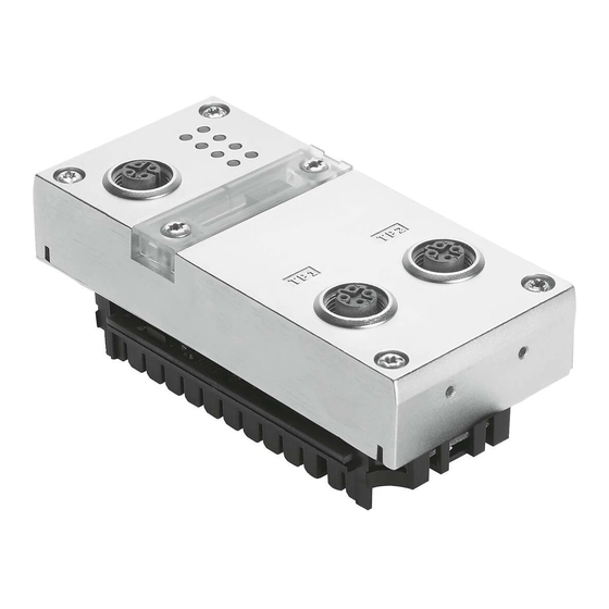
Use a protective cap or blanking plug to seal unused connections. You will then comply with protection class IP65/IP67 (see section 1.4). Information about fitting the CPX terminal can be found in the CPX system manual (P.BE−CPX−SYS−...). 1−3 Festo P.BE−CPX−PN IO−EN en 0710NH... - Page 20 Service interface for the Handheld CPX−FB33: 2 x M12 D−coded female (V24) 4−pin Type plate with MAC−ID CPX−FB34: 2 x Push−pull RJ45 copper Fig. 1/1: Connection and display elements on the CPX bus node 1−4 Festo P.BE−CPX−PN IO−EN en 0710NH...
- Page 21 Fig. 1/2: Dismantling/installing the bus node Note Whether the manifold base is metal or plastic, always use the suitable screws for the manifold base for plastic manifold bases: thread−cutting screws for metal manifold bases: screws with metric thread. 1−5 Festo P.BE−CPX−PN IO−EN en 0710NH...
- Page 22 3. Tighten the screws at first only by hand. Place the screws so that the self−cutting threads can be used. Tighten the screws with a Torx screwdriver size T10 with 1.1 Nm. 1−6 Festo P.BE−CPX−PN IO−EN en 0710NH...
-
Page 23: Settings Of The Dil Switches On The Bus Node
Disconnect the power supply before removing the cover. · Make sure that the seal is seated correctly when fitting · the cover. Tighten the two fastening screws at first by hand and · then with max. 0.4 Nm. 1−7 Festo P.BE−CPX−PN IO−EN en 0710NH... -
Page 24: Settingthe Dil Switches
4. Replace the cover (see section 1.2.1). DIL switch 1: Bus node operating mode DIL switch 2 only for operating mode Remote I/O: Diagnostic mode Fig. 1/3: Settings of the DIL switches on the bus node 1−8 Festo P.BE−CPX−PN IO−EN en 0710NH... - Page 25 All functions of the CPX terminal are controlled directly by the PROFINET IO controller, a PLC or a superordinate SPS: control of the CPX valve terminal (also described as IO Controller) data exchange between controller and modules parameterisation of the modules diagnostics. 1−9 Festo P.BE−CPX−PN IO−EN en 0710NH...
- Page 26 8−byte IO data field, e.g. with a PROFINET Controller. A superordinate controller can call up, e. g. status information of the valve terminal using this interface and match or optimise the controller accordingly with other system parts. 1−10 Festo P.BE−CPX−PN IO−EN en 0710NH...
- Page 27 The function of the DIL switch 2 depends on the setting of the DIL switch 1 or the set operating mode of the CPX terminal (see also Tab. 1/1): In the Remote Controller operating mode, DIL switch 2 is reserved for future expansions. 1−11 Festo P.BE−CPX−PN IO−EN en 0710NH...
- Page 28 Reserved for future extensions 2.1: ON 2.2: ON Diagnostic mode status bit occupies 8 IO bits, IO diagnostics interface 16 IO bits. Tab. 1/2: Setting the diagnostic mode with DIL switch 2 (Remote I/O operating mode) 1−12 Festo P.BE−CPX−PN IO−EN en 0710NH...
- Page 29 In the Remote Controller operating mode, select a bus node module from the CPX Remote Controller field devices group (separate group, not shown in the screenshot). Fig. 1/4: Selection of the diagnost. mode in the PLC software 1−13 Festo P.BE−CPX−PN IO−EN en 0710NH...
-
Page 30: Use Of The Memory Card
2. Remove the cover (observe section 1.2.1). 3. Remove the memory card from the bus node. 4. Replace the bus node. 5. Insert the memory card in the new bus node. 6. Replace the cover (observe section 1.2.1). 1−14 Festo P.BE−CPX−PN IO−EN en 0710NH... - Page 31 8. Start the automation program if necessary. 9. The controller recognises the bus node using the device name on the memory card and loads all required data. Further information about using the memory card can be found in section 2.2.1. 1−15 Festo P.BE−CPX−PN IO−EN en 0710NH...
-
Page 32: Connecting To The Network
SELV/PELV power supplies or integrated power supplies with similar protection. Installation guidelines The installation guidelines can be obtained via the PROFINET User Organisation: www.profinet.com Observe the instructions there. 1−16 Festo P.BE−CPX−PN IO−EN en 0710NH... - Page 33 Harting: eCon7100−B (IP65) Hirschmann: Octopus series (IP65) The integrated switch in the bus node enables the subdivision of the network into different segments (see also note about the maximum cable length in section 1.3.1). 1−17 Festo P.BE−CPX−PN IO−EN en 0710NH...
-
Page 34: Overview Of Connection Technology And Network Cables
Please also observe the relevant regulations in EN 60204 part 1. The CPX bus nodes for PROFINET support Crossover Detection. Thus patch cables or crossover cables can be optionally used. 1−18 Festo P.BE−CPX−PN IO−EN en 0710NH... - Page 35 Example: Connections between devices in the switch cabinet or terminal boxes with RJ45 connection and IP65/IP67 devices with M12 connection. Adapter examples: Lumberg: 0981 ENC 100 (RJ45/M12 adapter, M12 coupler, D−coded, mounting thread PG9, RJ45 coupling, 90 degrees) Harting: eCon 6050−BA 1−19 Festo P.BE−CPX−PN IO−EN en 0710NH...
-
Page 36: Network Interface Of The Cpx−Fb33
Tab. 1/4: Pin assignment of the network interfaces of the CPX−FB33 (M12 4−pin) Connection with plugs from Festo Connect the CPX terminal to the network with Festo plugs (type NECU−M−S−D12G4−C2−ET (part no. 543109). In order to comply with protection class IP65/IP67: Use Festo connectors. -
Page 37: Network Interface Of The Cpx−Fb34
You can optionally use patch cables or crossover cables for connecting your bus node to a network or PC. Connection with plugs from Festo Connect the CPX terminal to the network with Festo plugs (type FBS−RJ45−PP−GS (part no. 552000). In order to comply with protection class IP65/IP67: Use Festo connectors. -
Page 38: Compliance With Protection Class Ip65/Ip67
Service interface, M12 Connecting cable and plug for Protective cap type ISK−M12 the handheld (part no. 352059) If connection is not used Included in scope of delivery Tab. 1/6: Connections and covers for protection class IP65/IP67 1−22 Festo P.BE−CPX−PN IO−EN en 0710NH... -
Page 39: Pin Assignment Of Power Supply
The current consumption of a CPX terminal depends on the number and type of integrated modules and components. Read the information about the power supply as well as on the earthing measures to be carried out in the CPX system manual (P.BE−CPX−SYS−...). 1−23 Festo P.BE−CPX−PN IO−EN en 0710NH... - Page 40 4: Earth terminal Note the specifications on the plug : Operating voltage for electronics/sensors EL/SEN Load voltage for outputs Load voltage for valves Tab. 1/7: Pin assignment for system supply, additional supply and valve supply 1−24 Festo P.BE−CPX−PN IO−EN en 0710NH...
-
Page 41: Commissioning
Commissioning Chapter 2 2−1 Festo P.BE−CPX−PN IO−EN en 0710NH... -
Page 42: Configuration
....2−39 Check list for commissioning the CPX terminal ..... . . 2−40 2−2 Festo P.BE−CPX−PN IO−EN en 0710NH... -
Page 43: Commissioning
Also, certain functions, e.g. the IO Diagnostics Interface (STI), reduce the number of available IO bytes (in favour of status or diagnostics functions). Take account of this fact for the planning of your CPX terminal. 2−3 Festo P.BE−CPX−PN IO−EN en 0710NH... -
Page 44: Module Overview
(I: CPX−8DE) Digital 8−input module with 8DI−D 1 byte I channel diagnostics (I: CPX−8DE−D) Digital 16−input module 16DI 2 byte I (I: CPX−16DE) Digital 16−input module with 16DI−D 2 byte I channel diagnostics (I: CPX−16DE−D) 2−4 Festo P.BE−CPX−PN IO−EN en 0710NH... - Page 45 Number of occupied IO bytes in the Remote Controller operating mode: see Tab. 2/2 number of inputs which can be switched between 2 and 4 Tab. 2/1: Overview of electric CPX modules (bus node in Remote I/O operating mode) 2−5 Festo P.BE−CPX−PN IO−EN en 0710NH...
- Page 46 Module identifier in the hardware configuration of the programming software Note: In the handheld, the bus node is basically designated as ProfiNet Remote I/O" (independent from the operating mode) Tab. 2/2: Configuration of the bus node for the operating mode Remote Controller 2−6 Festo P.BE−CPX−PN IO−EN en 0710NH...
- Page 47 Pneumatic modules of type MPA2 each occupy 8−bit outputs, but only 4 bits are used. Further information about the pneumatics can be found in the corresponding pneumatics descriptions. 2−7 Festo P.BE−CPX−PN IO−EN en 0710NH...
- Page 48 (VI: CPX type 32: 1−4V...) MPA2 pneumatic module (type 32/33) MPA2G 1 byte O with electrical isolation (VI: CPX type 32−G: 1−4V...) Module identifier in the Handheld Tab. 2/4: Overview of MPA pneumatic modules 2−8 Festo P.BE−CPX−PN IO−EN en 0710NH...
-
Page 49: Device Master File (Gsd) And Symbol Files
The installation of the GSDM file is explained on the following pages. Symbol files Symbol files for Festo CPX terminals for displaying the CPX terminal in your configuration software can be found at the website address mentioned above. The integration of these symbol files is explained on the following pages. -
Page 50: Cpx Terminal Configuration With Siemens Step 7
Before commissioning, ensure that the connected elements (e.g. actuators) do not perform any undesired or uncontrollable movements. If necessary, disconnect the load power supply and compressed air supply. See also section 2.3, Check list for commissioning the CPX terminal. 2−10 Festo P.BE−CPX−PN IO−EN en 0710NH... - Page 51 4. Select the controller used (PLC/Master): Insert > Station > ... (e.g. SIMATIC 300 Station). 5. Open the project by clicking on the plus symbol (on the left next to the project symbol and the project name). 2−11 Festo P.BE−CPX−PN IO−EN en 0710NH...
- Page 52 The child window symbolises the rack rail (profile rail) of your controller system. You compile the individual elements of your controller in this child window and thus form the basis for your PROFINET automation system. 2−12 Festo P.BE−CPX−PN IO−EN en 0710NH...
- Page 53 (Rail) 6. Add your CPU and a PROFINET IO system to the hardware configuration: Drag the corresponding catalogue elements (symbols) into the Rack Rail window (3 or 4 in Fig. 2/1). 2−13 Festo P.BE−CPX−PN IO−EN en 0710NH...
- Page 54 Options > Update Catalog All available CPX modules in the hardware catalogue are displayed under PROFINET IO > Additional Field Devices > Valves > Festo CPX−Terminal. You can start the selection and configuration of your modules. 2−14 Festo P.BE−CPX−PN IO−EN en 0710NH...
- Page 55 (e.g. CPX or CPX−01) and confirm the entry by clicking on Assign Name". CPX terminal characteristics, station selection and IP addressing 1. Start the PROFINET hardware configuration in your configuration and programming software (e.g. HW Config in Siemens STEP 7). 2−15 Festo P.BE−CPX−PN IO−EN en 0710NH...
- Page 56 Fig. 2/2: Station selection using Siemens STEP 7 HW Config 2. If the hardware catalogue has not been opened: Click on the catalogue symbol (1 in Fig. 2/2) or use the keyboard combination [Ctrl] + [K]. The hardware catalogue is displayed. 2−16 Festo P.BE−CPX−PN IO−EN en 0710NH...
- Page 57 \PROFINET−IO\Weitere Feldgeräte\Ventile\ Festo CPX−Terminal If the directory Valves\Festo CPX−Terminal" (Ventile\ Festo CPX−Terminal) is not displayed, repeat the installa tion of the device master file (GSDML, see section Instal ling GSDML file). 4. Drag the CPX" station symbol on to the bus line of the PROFINET IO system (2 in Fig.
- Page 58 IP address (automatic addres sing using the DHCP server integrated in the controller). If you would like to accept the specified IP address, you can skip the next two steps. 2−18 Festo P.BE−CPX−PN IO−EN en 0710NH...
- Page 59 Also check that the IP address can be used in your automation network (no duplicate address assignment etc.). 9. Confirm your entries by clicking on OK" (twice if necessary). Fig. 2/4: CPX terminal characteristics IP addressing 2−19 Festo P.BE−CPX−PN IO−EN en 0710NH...
- Page 60 Pneumatic modules and Technology modules. Fig. 2/5: CPX terminal configuration with Siemens STEP 7 HW Config 1. Start the PROFINET hardware configuration in your configuration and programming software (e.g. HW Config in Siemens STEP 7). 2−20 Festo P.BE−CPX−PN IO−EN en 0710NH...
- Page 61 \PROFINET−IO\Weitere Feldgeräte\Ventile\ Festo CPX−Terminal If the directory Valves\Festo CPX−Terminal" (Ventile\ Festo CPX−Terminal) is not displayed, repeat the installa tion of the device master file (GSDML, see section Installing GSDML file). 4. Click on the symbol of the CPX terminal to be configured in the PROFINET hardware configuration (HW Config, 1 in Fig.
- Page 62 Check the settings of the DIL switches before selecting the catalogue element (see section 1.2.2). Ensure that the selected setting for operating mode and diagnostics mode at the bus node matches the function of the catalogue element. 2−22 Festo P.BE−CPX−PN IO−EN en 0710NH...
- Page 63 CPX Remote Controller field devices group (separate group, not shown in the screenshot). Fig. 2/6: Bus node selection in the course of the CPX terminal configuration with Siemens STEP 7 HW Config 2−23 Festo P.BE−CPX−PN IO−EN en 0710NH...
- Page 64 HW Config. A change is rarely required. 1. Double click on row 0 of the configuration table. The Properties CPX" window is displayed see Fig. 2/7. Fig. 2/7: Changing the diagnostics address with Siemens STEP 7 HW Config 2−24 Festo P.BE−CPX−PN IO−EN en 0710NH...
- Page 65 (The available address range depends on the controller used see manufacturer documentation). 4. Confirm the entry with OK". The modified address is displayed in the configuration table. Further information about diagnostics: section 3.5, Diagnostics via PROFINET. 2−25 Festo P.BE−CPX−PN IO−EN en 0710NH...
-
Page 66: Configuration Example
CP−EL Input module (32I) (module no. 3) and MPA1 pneumatics Sensor CP−CL output module (4O) on Cylinder CP string 4 MPA−CPI valve terminal on CP string 1 Fig. 2/8: CPX example terminal (with CP interface) 2−26 Festo P.BE−CPX−PN IO−EN en 0710NH... - Page 67 MPA1 pneumatic module (VI: CPX type 32: 1−8V...) MPA1 pneumatic module (VI: CPX type 32: 1−8V...) ) Passive module Tab. 2/6: Configuration and addressing for CPX example terminal (addresses used from input/output word 42) 2−27 Festo P.BE−CPX−PN IO−EN en 0710NH...
-
Page 68: Procedure For Replacing A Bus Node
6. Replace the cover (observe section 1.2.1). 7. Switch on the power supply. 8. Start the automation program if necessary. 9. The controller recognises the bus node using the device name on the memory card and loads all required data. 2−28 Festo P.BE−CPX−PN IO−EN en 0710NH... - Page 69 4. Start your configuration and programming software (e. g. Siemens STEP 7). 5. Perform a new configuration (hardware configuration, in STEP 7 using HW Config). 6. The controller loads all required data into the bus node. 2−29 Festo P.BE−CPX−PN IO−EN en 0710NH...
-
Page 70: Configuration In The Remote Controller Operating Mode
CPX terminal configuration. 6. Perform the bus node selection (station selection) with the CPX remote controller station type (see section 2.1.4 and 1 in Fig. 2/9). The bus node is thus configured as Remote Controller. 2−30 Festo P.BE−CPX−PN IO−EN en 0710NH... - Page 71 2. Commissioning Fig. 2/9: Bus node configuration in the Remote Controller operating mode with Siemens STEP 7 HW Config 2−31 Festo P.BE−CPX−PN IO−EN en 0710NH...
-
Page 72: Parameterisation
CPX bus node. Details can be found in Fig. 2/10 and the following explanations. Note The start parameter set is loaded again (according to the rules described above) after every interruption of the network connection. 2−32 Festo P.BE−CPX−PN IO−EN en 0710NH... - Page 73 Afterwards, the bus node distributes the parameter set to the modules. Sequence with system start parameter = 1 [Saved Parameters] The start parameters saved in the CPX bus node are loaded ( 2 in Fig. 2/10). 2−33 Festo P.BE−CPX−PN IO−EN en 0710NH...
-
Page 74: Parameterisation Of The Cpx Terminal With Siemens Step
2.2.2 Parameterisation of the CPX terminal with Siemens STEP 7 Setting system parameters 1. Start the PROFINET hardware configuration in your configuration and programming software (e. g. HW Config in Siemens STEP 7). Fig. 2/11: Setting system parameters with Siemens STEP 7 2−34 Festo P.BE−CPX−PN IO−EN en 0710NH... - Page 75 Entries remanent on Power On Active" The entries in the error memory are retained during Power OFF/ON. Entries remanent on Power On Inactive" The entries in the error memory are cleared during Power OFF/ON. 2−35 Festo P.BE−CPX−PN IO−EN en 0710NH...
- Page 76 Further information about parameterisation can be found in the CPX system manual (P.BE−CPX−SYS−...) in appendix B. Monitoring short/circuit overload sensor supply Monitoring short/circuit overload outputs Monitoring short/circuit overload valves Monitoring undervoltage outputs/valves OUT/VA 2−36 Festo P.BE−CPX−PN IO−EN en 0710NH...
- Page 77 2. Commissioning Setting module parameters 1. Start the PROFINET hardware configuration in your configuration and programming software (e. g. HW Config in Siemens STEP 7). Fig. 2/12: Setting module parameters with Siemens STEP 7 2−37 Festo P.BE−CPX−PN IO−EN en 0710NH...
-
Page 78: Parameterisation With The Handheld
System parameters Module parameters Diagnostics memory parameters can also be parameterised while the handheld is is use. Information about operating the handheld can be found in the manual for the handheld P.BE−CPX−MMI−1−... 2−38 Festo P.BE−CPX−PN IO−EN en 0710NH... -
Page 79: Application Example For The Parameterisation
Signal extension time set to 50 ms: Reliable recording of the signals by the controller. The value of this parameter is set for the complete mod ule, however must be activated/deactivated separately for each input channel. 2−39 Festo P.BE−CPX−PN IO−EN en 0710NH... -
Page 80: Check List For Commissioning The Cpx Terminal
(see also start parameterisation in section 2.2.1). Use spot checks if necessary to check the parameterisa · tion, e.g. with the configuration program or with the Handheld. 2−40 Festo P.BE−CPX−PN IO−EN en 0710NH... -
Page 81: Diagnosis
Diagnosis Chapter 3 3−1 Festo P.BE−CPX−PN IO−EN en 0710NH... - Page 82 ..... 3−16 3.5.3 User−specific diagnostics with Siemens STEP 7 ....3−18 3−2 Festo P.BE−CPX−PN IO−EN en 0710NH...
-
Page 83: Diagnosis
PROFINET PROFINET standard Detailed module−related and channel−related fault recognition in the online mode of the configuration software and in the PLC user program. Tab. 3/1: Overview of the diagnostics options of the CPX terminal 3−3 Festo P.BE−CPX−PN IO−EN en 0710NH... - Page 84 3. Diagnosis Note Note that the diagnostic information shown can depend on the settings (see section 1.2.2) as well as on the parameterisation (see section 2.2) of the CPX terminal. 3−4 Festo P.BE−CPX−PN IO−EN en 0710NH...
-
Page 85: Diagnostics Via Leds
CPX bus node. CPX−specific LEDs PS: Power system PL: Power load SF: System Failure M: Modify PROFINET−specific LEDs NF: Network Failure TP1: Link/Traffic 1 TP2: Link/Traffic 2 Fig. 3/1: LEDs on the CPX bus node 3−5 Festo P.BE−CPX−PN IO−EN en 0710NH... - Page 86 The M LED lights or flashes if para meterisation is changed or force mode is active Only if connection is used: Steady light: Connection active Flashing: Data transmission is running Tab. 3/2: Normal operating status 3−6 Festo P.BE−CPX−PN IO−EN en 0710NH...
-
Page 87: Network Error Display Led Nf / Connection Status Led Tp1, Tp2
(section 2.1.4) Appears as lit in the case of fast flickering. The light intensity depends on data traffic. Tab. 3/3: Fault diagnostics using the LEDs NF and TP1/TP2 3−7 Festo P.BE−CPX−PN IO−EN en 0710NH... -
Page 88: Fault Displays Of The Leds For System Diagnosis Ps, Pl, Sf
The load voltage supply will be · LED flashes switched on again automatically after the undervoltage has been eliminated (default) Power Off/On is necessary · Tab. 3/4: Fault diagnostics using the LEDs PS and PL 3−8 Festo P.BE−CPX−PN IO−EN en 0710NH... - Page 89 The system error LED flashes depending on the class of error which has occurred. Error class 1 (minor error): one flash, pause Error class 2 (error): flash twice, pause Error class 3 (serious error): flash three times, pause Tab. 3/5: Fault diagnostics using the LED SF 3−9 Festo P.BE−CPX−PN IO−EN en 0710NH...
- Page 90 CPX system manual P.BE−CPX−SYS−...). LED flashes The display of the Force function (LED flashes) has priority over the display of the setting for the system start (LED lights). Tab. 3/6: Messages of the LED M 3−10 Festo P.BE−CPX−PN IO−EN en 0710NH...
-
Page 91: Diagnostics Via Status Bits
Fault at output Fault at input Fault on analogue module/ technology module Undervoltage Type of fault Short circuit/overload Wire break Other faults Tab. 3/7: Status bits of the CPX bus node (optional) 3−11 Festo P.BE−CPX−PN IO−EN en 0710NH... -
Page 92: Diagnostics Via The I/O Diagnostic Interface (Sti)
1.2.2 and other explanations about the configuration in section 2.1.4). Further information can be found in the CPX system manual P.BE−CPX−SYS−... in the section Diagnostics and error handling. 3−12 Festo P.BE−CPX−PN IO−EN en 0710NH... -
Page 93: Diagnostics Via Profinet
Depending on the parameterisation, the outputs (valves and electric outputs) will be switched off (factory setting), switched on or retain their status. Further information about the Fail Safe setting can be found in the CPX system manual P.BE−CPX−SYS−... 3−13 Festo P.BE−CPX−PN IO−EN en 0710NH... - Page 94 PLC stop, network interruption or fault: Single−solenoid valves move to the basic position. Double−solenoid valves remain in the current position. Mid−position valves move to the mid−position (depend ing on valve type: pressurised, exhausted or blocked). 3−14 Festo P.BE−CPX−PN IO−EN en 0710NH...
- Page 95 Short circuit in the CP string (CP line) reserved reserved 1030 Slave has no bus connection reserved 1031 Channel failed bold = relevant for CPX−FB33/FB34 Tab. 3/8: Error types for the diagnostics via PROFINET 3−15 Festo P.BE−CPX−PN IO−EN en 0710NH...
-
Page 96: Online Diagnostics With Siemens Step
3.5.2 Online diagnostics with Siemens STEP 7 1. Start the PROFINET hardware configuration in your configuration and programming software (e. g. HW Config in Siemens STEP 7). Fig. 3/2: Online diagnostics with Siemens STEP 7 3−16 Festo P.BE−CPX−PN IO−EN en 0710NH... - Page 97 6. Click on the event and then on Display" (show) 5. Diagnostics details are displayed in a new window 6. These provide more precise information for further processing. The information is independent of the controller used. 3−17 Festo P.BE−CPX−PN IO−EN en 0710NH...
-
Page 98: User−Specific Diagnostics With Siemens Step
RALRM information from an IO device and provides this information as an output parameter Tab. 3/9: Intended use (meaning) of the Organisation Modules OM 82 and OM 86 and the Function Module SFB 54 3−18 Festo P.BE−CPX−PN IO−EN en 0710NH... - Page 99 Starting address of the module with alarm :=”DB_ALARM”.LEN Length of alarm information TINFO:=”DB_ALARM”.TINFO Target range OM start information (Task information) AINFO:=”DB_ALARM”.AINFO Target range Header / Additional information (Alarm information) Fig. 3/3: Program example in STL for reading diagnostics information 3−19 Festo P.BE−CPX−PN IO−EN en 0710NH...
- Page 100 3. Diagnosis 3−20 Festo P.BE−CPX−PN IO−EN en 0710NH...
- Page 101 Technical appendix Appendix A A−1 Festo P.BE−CPX−PN IO−EN en 0710NH...
-
Page 102: A. Technical Appendix
..... . . A−3 Technical specifications of bus node CPX−FB34 ..... . . A−4 A−2 Festo P.BE−CPX−PN IO−EN en 0710NH... - Page 103 Power failure bridging time 10 ms PROFINET CPX−FB33 Protocol PROFINET RT Specification Network: Industrial Ethernet, based on IEEE 802.3; see also PROFINET Installation Guide PNIO RT: IEC 61158, IEC 61784 Transmission speed 100 Mbit/s, Switched Fast Ethernet A−3 Festo P.BE−CPX−PN IO−EN en 0710NH...
- Page 104 Power failure bridging time 10 ms PROFINET CPX−FB34 Protocol PROFINET RT Specification Network: Industrial Ethernet, based on IEEE 802.3; see also PROFINET Installation Guide PNIO RT: IEC 61158, IEC 61784 Transmission speed 100 Mbit/s, Switched Fast Ethernet A−4 Festo P.BE−CPX−PN IO−EN en 0710NH...
- Page 105 Index Appendix B B−1 Festo P.BE−CPX−PN IO−EN en 0710NH...
-
Page 106: B. Index
............B−1 B−2 Festo P.BE−CPX−PN IO−EN en 0710NH... - Page 107 1−9 , 1−10 , 2−5 , 2−30 I/O diagnostic interface ......3−12 C−3 Festo P.BE−CPX−PN IO−EN en 0710NH...
- Page 108 ......2−39 Module parameters ......2−37 C−4 Festo P.BE−CPX−PN IO−EN en 0710NH...
- Page 109 ........C−5 Festo P.BE−CPX−PN IO−EN en 0710NH...
- Page 110 ......1−24 VTSA pneumatics (ISO) ......2−7 C−6 Festo P.BE−CPX−PN IO−EN en 0710NH...
Need help?
Do you have a question about the CPX-FB33 and is the answer not in the manual?
Questions and answers