Festo CPX-FB33 Brief Instructions
Bus node
Hide thumbs
Also See for CPX-FB33:
- Manual (160 pages) ,
- Electronics description (134 pages) ,
- Operating instructions manual (40 pages)
Table of Contents
Advertisement
Quick Links
CPX-(M)-FB33/34/35/43/44/45
Bus node
Brief instructions
8127864
2020-04d
[8127866]
Translation of the original instructions
© 2020 all rights reserved to Festo SE & Co. KG
PI PROFIBUS PROFINET
is a registered trademark of its respective trademark
®
holder in certain countries.
1
About this document
1.1
Applicable Documents
All available documents for the product è www.festo.com/sp.
Document
CPX system description (CPX-SYS-...)
Brief instructions for bus node
Operating instructions for bus node
Tab. 1 Applicable Documents
2
Safety
2.1
Safety Instructions
–
Only use the product in original status without unauthorised modifications.
–
Only use the product if it is in perfect technical condition.
–
Observe labelling on the product.
–
Store the product in a cool, dry, UV-protected and corrosion-protected envir-
onment. Ensure that storage times are kept to a minimum.
–
Before working on the product, switch off the power supply and secure it
against being switched on again.
–
This product can generate high frequency malfunctions, which may make it
necessary to implement interference suppression measures in residential
areas.
–
Comply with the handling specifications for electrostatically sensitive devices.
2.2
Intended Use
The bus node is intended exclusively for operation as a station (IO Device) in the
industrial Ethernet system PROFINET IO.
The product may only be used in combination with the CPX Terminal in an indus-
trial environment.
Festo SE & Co. KG
Ruiter Straße 82
73734 Esslingen
Germany
+49 711 347-0
www.festo.com
8127864
Contents
Detailed information on the CPX terminal
Essential information on the product
Detailed information on the product
3
Configuration
3.1
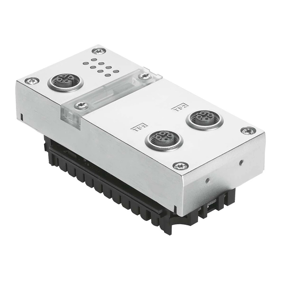
Product design
1 LED Displays
2 Memory card (only for
FB33/34/35)
3 Network connection
Fig. 1 Connection and display components
3.2
Product variants
The following software and hardware revisions are a prerequisite for using the
functions:
Function
Bus bus node revision number
Software
Priority start-up (Fast Start-up)
From Rev 12
Identification & Maintenance
From Rev 14
(I&M)
PROFIenergy
From Rev 20
Media Redundancy Protocol
From Rev 20
(MRP)
Media Redundancy for Planned
From Rev 50
Duplication (MRPD)
S2 system redundancy
From Rev 50
Isochronous real time (IRT)
From Rev 21
Tab. 2 Required revision numbers for using the functions
The revision numbers of the hardware and software for the bus node can be
checked with the control software, the Festo Maintenance Tool (FMT) or the
Festo Field Device Tool (FFT).
3.3
LED displays
LED
Network status LEDs
NF
Network Failure (red)
M/P
Maintenance/PROFIenergy
(green or yellow)
TP1
Link/Traffic 1 (green)
TP2
Link/Traffic 2 (green)
Tab. 3 LEDs on the bus node
3.4
Control Elements
Fig. 2 Control elements for PROFINET
6 Product labelling
Hardware
From Rev 11
From Rev 1
From Rev 1
From Rev 1
From Rev 45
From Rev 45
From Rev 1
LED
CPX-specific LEDs
PS
Power System (green)
PL
Power Load (green)
SF
System Failure (red)
M
Modify (yellow)
1 Memory card
2 DIL switch: operating mode
3 DIL switch: diagnostics mode
Advertisement
Table of Contents

Related Manuals for Festo CPX-FB33


Summary of Contents for Festo CPX-FB33
- Page 1 The revision numbers of the hardware and software for the bus node can be onment. Ensure that storage times are kept to a minimum. checked with the control software, the Festo Maintenance Tool (FMT) or the – Before working on the product, switch off the power supply and secure it Festo Field Device Tool (FFT).
- Page 2 From Rev 12 CPX-SK-3 From Rev 30 Tab. 6 Compatibility of the memory cards depending on the bus node revision Connecting Elements Pin allocation of the network interface of the bus node CPX-FB33/43 (M12) Bushing Signal Explanation M12, D-coded Transmitted data (Transmit Data) + Received data (Receive Data) + TD–...
- Page 3 CPX-M-FB35/45 only permissible on metal linking. Tab. 13 Special characteristics of CPX-(M)-FB43/44/45 Disassembly 1. Unscrew screws. Network 2. Carefully lift the bus node. Characteristics CPX-FB33/43 CPX-M- CPX-M- Assembly FB34/44 FB35/45 1. Check seal and sealing surfaces and insert the bus node.
Need help?
Do you have a question about the CPX-FB33 and is the answer not in the manual?
Questions and answers