
Related Manuals for Festo CPX-FB36


Summary of Contents for Festo CPX-FB36
- Page 1 Terminal CPX Bus node CPXFB36 Description Network protocol EtherNet/IP Modbus TCP Industrial Ethernet 2-Port 8024075 en 1611a [8067476]...
- Page 3 ....... . . 8024075 E (Festo AG & Co. KG, D‐73726 Esslingen, 2016) Internet: http://www.festo.com E-mail: service_international@festo.com...
- Page 4 Contents and general instructions ® ® ® ® EtherNet/IP , Modbus , ROCKWELL AUTOMATION , SPEEDCON are registered trade marks of the respective trademark owners in certain countries. Festo CPX-FB36-EN en 1611a English...
- Page 5 ........1-22 Festo CPX-FB36-EN en 1611a English...
- Page 6 ......... . 2-10 Notes on commissioning of the CPX-FB36 ......
- Page 7 ........B-14 Address assignment after extension/conversion ..... . B-20 Festo CPX-FB36-EN en 1611a English...
- Page 8 Contents and general instructions EtherNet/IP Objects of the CPX-FB36 ......Overview of Ethernet/IP objects .
- Page 9 Contents and general instructions Modbus® TCP objects of the CPX-FB36 ......Overview of Modbus® TCP objects .
- Page 10 Intended use The bus node described in this description is intended exclus ively for use in CPX terminals from Festo for installation in a machine or automated system. In combination with a CPX terminal, the bus node is used for communication as a participant in networks with the proto...
- Page 11 Make sure that nobody enters the positioning range of • the actuators. Switching off the compressed air or load voltage is not a suit able locking mechanism. Unintentional movement of actuat ors may occur in the event of a malfunction. Festo CPX-FB36-EN en 1611a English...
- Page 12 – the applicable regulations for accident prevention and occupational safety – the documentation for the product. Service Consult your local Festo repair service if you have any tech nical problems. Festo CPX-FB36-EN en 1611a English...
- Page 13 Notes regarding this description This description contains specific information on the installa tion, configuration, parameterisation, commissioning, pro gramming and diagnostics with the CPX-FB36 bus node for EtherNet/IP and Modbus® TCP. An overview of the structure of user documentation for the CPX terminal can be found in the CPX system description (è...
- Page 14 ... means that damage to property can occur if this warning is not observed. In addition, the following pictogram marks passages in the text that describe activities involving electrostatic sensitive devices: Electrostatically sensitive devices: Incorrect handling can cause damage to devices. Festo CPX-FB36-EN en 1611a English...
- Page 15 Text designations Bullet points denote activities that can be carried out in • any order. 1. Numerals label activities that must be carried out in the sequence specified. – Arrowheads indicate general lists. XIII Festo CPX-FB36-EN en 1611a English...
- Page 16 Collective term for the various modules which can be integrated into the CP system (decentralised installation system). CPX-CP interface Interface for connecting decentrally arranged CP modules to a CPX terminal. CPX-FMT Festo Maintenance Tool for configuration and parameterisation of CPX terminals. CPX-MMI Operator unit for commissioning and service purposes. CPX modules Collective term for electric modules which can be incorporated into a CPX terminal: bus nodes, I/O modules and function modules (technology mod...
- Page 17 Input/output signal of an I/O module; also referred to as a process signal. I/Os Analogue or digital inputs and outputs. Modbus TCP Communication protocol via TCP/IP in automation technology. Digital output Tab. 0/2: CPX-specific terms and abbreviations - part 2 Festo CPX-FB36-EN en 1611a English...
- Page 18 They provide outputs (working ports) for connecting actuators, e.g. cylinders. They form the pneumatic side of the CPX terminal. Status bits Internal inputs that supply coded common diagnostic messages è Function module Technology module Tab. 0/3: CPX-specific terms and abbreviations - part 3 Festo CPX-FB36-EN en 1611a English...
- Page 19 0 … 65,536 Unsigned integer USINT 8 bit 0 … 256 Unsigned Short Integer WORD 16 bit 0000 … FFFF Bit field 1) Dependent on the data types used Tab. 0/4: Data types used XVII Festo CPX-FB36-EN en 1611a English...
- Page 20 Contents and general instructions XVIII Festo CPX-FB36-EN en 1611a English...
- Page 21 Installation Chapter 1 Installation Festo CPX-FB36-EN en 1611a English...
-
Page 22: Table Of Contents
........1-22 Festo CPX-FB36-EN en 1611a English... -
Page 23: Installation
Ensuring the required degree of protection Use cover caps to seal unused connections • (è 1.4 Ensuring the degree of protection). Information about mounting of the CPX terminal can be found in the CPX system description (è P.BE-CPX-SYS-...). Festo CPX-FB36-EN en 1611a English... -
Page 24: Dismantling And Mounting
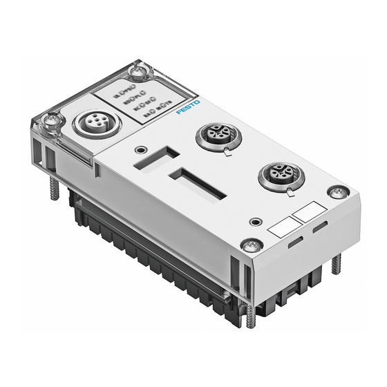
DIL switches Service interface 1) 2× socket, M12, D-coded, 4-pin 2) Socket, M12, A-coded, 5-pin; for the control device CPX-MMI or Festo Maintenance Tool CPX-FMT Fig. 1/1: Connection and display components 1.1.2 Dismantling and mounting The bus node is installed in an interlinking block of the CPX terminal (è... - Page 25 2. Push the bus node carefully and without tilting into the interlinking block up to the stop. 3. Turn the screws into the existing thread. 4. Tighten the screws in diagonally opposite sequence. Tightening torque: 1 Nm ± 10 %. Festo CPX-FB36-EN en 1611a English...
-
Page 26: Settings Of The Dil Switches
3. Remove the DIL switch cover. Attaching the DIL switch cover 1. Put the DIL switch cover in place. Make sure that the seal is seated correctly. 2. Tighten the screws. Tightening torque: max. 0.4 Nm. Festo CPX-FB36-EN en 1611a English... - Page 27 1.2.3 Setting the DIL switches Procedure 1. Switch off power supply. 2. Remove the DIL switch cover (è 1.2.1). 3. Make the settings for the DIL switches (è 1.2.4 … 1.2.6). 4. Re-attach the DIL switch cover (è 1.2.1). Festo CPX-FB36-EN en 1611a English...
-
Page 28: Setting The Operating Mode And Network Protocol
Network protocol DIL 1.2: OFF EtherNet/IP (Factory setting) The CPX terminal uses the EtherNet/IP network protocol. DIL 1.2: ON Modbus®TCP The CPX terminal uses the Modbus® TCP network protocol. Tab. 1/2: Setting the network protocol Festo CPX-FB36-EN en 1611a English... - Page 29 The system control ler carries out this adjustment automatically. Manual manip ulation, e.g. a reconfiguration of the CPX terminal or manual adaptation of the hardware and network configuration, are not required. Festo CPX-FB36-EN en 1611a English...
- Page 30 DIL 3.7: = 2 + 4 + 32 = 38 (Host-ID) DIL 3.6: = 32 DIL 3.5: Set IP address: 192.168.1.038 DIL 3.4: DIL 3.3: DIL 3.2: DIL 3.1: Tab. 1/5: Example – IP addressing 1-10 Festo CPX-FB36-EN en 1611a English...
-
Page 31: Connecting To The Network
An access password protects only against accidental changes. Note Assemblies with Ethernet interfaces should only be oper ated in networks if all connected network components are supplied by PELV circuits or integrated circuits with equi valent protection. 1-11 Festo CPX-FB36-EN en 1611a English... - Page 32 IP20, IP65 or IP67. – Unmanaged Switches: For small networks with a low network load or minimal requirements for determinism – Managed Switches: For comprehensive networks with diagnostics and monit oring functions 1-12 Festo CPX-FB36-EN en 1611a English...
-
Page 33: Overview Of Connection Technology And Network Plug Connectors
Overview of connection technology and network plug connectors RJ45 to M12 converter For EtherNet/IP installations, it may be necessary to change between RJ45- and M12 connection technology. Example: Connections between devices in a control cabinet and IP65/IP67 devices. 1-13 Festo CPX-FB36-EN en 1611a English... -
Page 34: Cable Specification
1.3.1 General instructions) Tab. 1/7: Cable specification Note When mounting the CPX terminal on a moving part of a machine: Use network wiring with tension relief. • Observe corresponding stipulations of • IEC 60204/EN 60204. 1-14 Festo CPX-FB36-EN en 1611a English... - Page 35 Pin allocation of the network connections [X1] and [X2] If the QuickConnect function has been activated, the crossov er detection function is not available. Further notes on wiring with deactivated crossover detection can be found in chapter 2.1.2. 1-15 Festo CPX-FB36-EN en 1611a English...
- Page 36 1. Installation Connection with plug connector by Festo The CPX terminal is connected to the network with plugs NECU-M-S-D12G4-C2-ET. The plugs are designed for network lines with cable diamet ers of 6 ... 8 mm. To comply with degree of protection IP65/IP67: Use Festo plugs.
- Page 37 Operator unit CPX-MMI – “Festo Maintenance Tool” (CPX-FMT) program – “BOOTP-DHCP Server” program from “Rockwell Auto mation” Use this setting to activate the storage of network settings in a non-volatile memory of the bus node. 1-17 Festo CPX-FB36-EN en 1611a English...
- Page 38 IP address (binary coded) If all of the switch elements of DIL switch3 are set to ON when the bus node is switched on, all network parameters will be reset to the factory setting. 1-18 Festo CPX-FB36-EN en 1611a English...
- Page 39 1. Installation Factory settings of the CPX-FB36 IP address – octet 1 … 3 192.168.1 IP address – octet 4 Network mask 255.255.255.0 Gateway 0.0.0.0 1) Dynamic addressing via DHCP/BOOTP Tab. 1/10: Factory settings Alternatively, change the first 3 octets of the IP address with: •...
- Page 40 Setting via attribute 6 (Forced Interface Speed) of the Ether net link object: – 10 Mbit/s – 100 Mbit/s Duplex mode Setting via attribute 6 (control bits, bit 1) of the Ethernet link object: – Half duplex – Full duplex 1-20 Festo CPX-FB36-EN en 1611a English...
- Page 41 Network connection (M12) Plug connector NECU-M-S-D12G4-C2-ET ISK-M12 Service interface (M12) Connecting cable KV-M12-M12-... ISK-M12 1) Connecting cable for the operator unit (CPX-MMI) Tab. 1/11: Connection technology and cover caps for degree of protection IP65/IP67 (examples) 1-21 Festo CPX-FB36-EN en 1611a English...
- Page 42 Observe the information on power supply (è electrical con nection) as well as on the earthing measures to be carried out (è potential equalisation) contained in the CPX system de scription. 1-22 Festo CPX-FB36-EN en 1611a English...
- Page 43 Preparing for commissioning Chapter 2 Preparing for commissioning Festo CPX-FB36-EN en 1611a English...
- Page 44 ......... . 2-10 Notes on commissioning of the CPX-FB36 ......
-
Page 45: Preparing For Commissioning
“Multicast” telegram is to be transferred. Therefore, these switches send the “Multicast” telegrams to all devices in the network. This results in an EtherNet/IP participant receiving numerous unnecessary telegrams, which must then be discarded from Festo CPX-FB36-EN en 1611a English... - Page 46 The “IGMP snooping” function cannot work properly without these “IGMP queries”. Segmentation of the network Split the machine into smaller network segments. This can • be realised without changing the network cabling, for example, by using VLANs. Festo CPX-FB36-EN en 1611a English...
-
Page 47: Quickconnect
3. Use the same settings for baud rate and duplex mode at the counterpart station (e.g. switch) and at the PLC as in the bus node. For fast connection set-up: – 100 MBit/s – Full duplex 4. Activate “QuickConnect” in the PLC or the control program. Festo CPX-FB36-EN en 1611a English... - Page 48 MDI MDIX MDI MDIX MDI MDIX PLC or switch I/O device (e.g. B. CPX-FB36) Patch cable Fig. 2/1: QuickConnect line topology with patch cables The bus node corresponds to a “Class A device” in accord ance with the EtherNet/IP specification. When switched on, the bus node requires less than 350 ms to accept a TCP con...
- Page 49 CPX-8DE-8DA Digital 16-off input/output module, CPXL8DE8DA with terminal strip 16KL3POL Analogue 2-off input module CPX2AEUI (voltage/current) Analogue 2-off output module CPX2AAUI (voltage/current) Analogue 4-off input module (current) CPX4AEI Tab. 2/1: CPX modules, which support “QuickConnect” Festo CPX-FB36-EN en 1611a English...
-
Page 50: Device Level Ring" Protocol (Dlr)
The Device Level Ring protocol (DLR) allows multiple devices to be operated in a ring topology. Requirements All DLR devices feature an integrated Ethernet switch with at least 2 external ports and support the DLR Protocol. Festo CPX-FB36-EN en 1611a English... - Page 51 • based” or “announce-based” configuration. Operation as a ring supervisor is not possible. This func tion is normally executed by an EtherNet/IP scanner. The DLR protocol is configured via the DLR object (class code 47 Festo CPX-FB36-EN en 1611a English...
-
Page 52: Modbus® Tcp Protocol
In order to configure the CPX terminal for Modbus® TCP, the Modbus® addresses of the data and of the inputs and out puts of the CPX terminal are required. (è D). Addressing examples can be found in the appendix (è D.6.1). 2-10 Festo CPX-FB36-EN en 1611a English... -
Page 53: Notes On Commissioning Of The Cpx-Fb36
Note The bus node CPX-FB36 can be used on all EtherNet/IP or Modbus® TCP controllers. The following section describes the configuration and com missioning procedure using the example of a controller from Allen-Bradley with the help of the “Studio 5000”... -
Page 54: Switching On The Power Supply
(è Tab. 2/5) – Bus node configured and higher-order controller (PLC) is in the Run stop mode (è Tab. 2/6) Information on diagnostics using the LED displays can be found in section 4.2. 2-12 Festo CPX-FB36-EN en 1611a English... - Page 55 – Operating and load voltage present Lights up green (in the approved range) 1) Display dependent on monitoring and signal from the connected device. Tab. 2/4: Status LEDs after switch-on – bus node not configured 2-13 Festo CPX-FB36-EN en 1611a English...
- Page 56 – Operating and load voltage present Lights up green (in the approved range) 1) Display dependent on monitoring and signal from the connected device. Tab. 2/5: Status LEDs after switch-on – bus node configured, PLC in the Stop mode 2-14 Festo CPX-FB36-EN en 1611a English...
- Page 57 – Operating and load voltage present Lights up green (in the approved range) 1) Display dependent on monitoring and signal from the connected device. Tab. 2/6: Status LEDs after switch-on – bus node configured, PLC in the Run mode 2-15 Festo CPX-FB36-EN en 1611a English...
-
Page 58: Participants In The Network
Install EDS files – Enter participant properties manually – Import participant properties As soon as the CPX terminal has been registered as a poten tial network participant, it can be added to a network. 2-16 Festo CPX-FB36-EN en 1611a English... - Page 59 Commissioning Chapter 3 Commissioning Festo CPX-FB36-EN en 1611a English...
- Page 60 ......... . 3-31 Festo CPX-FB36-EN en 1611a English...
-
Page 61: Commissioning
CPX- configuration of the par (è 3.1.3) FMT and import of the ticipant and paramet settings to the “Studio erisation of the CPX ter 5000” configuration pro minal. gram. Tab. 3/1: Configuration methods Festo CPX-FB36-EN en 1611a English... -
Page 62: Configuration With Eds File
– Icon file for representing the CPX terminal or mode in the configuration program. Tab. 3/2: Device description files for CPX-FB36 The current device description file is available on the Festo Support Portal (è www.festo.com/sp). Festo CPX-FB36-EN en 1611a English... - Page 63 [Tools] , [EDS Hardware Installation Tool] Fig. 3/1: Starting EDS Wizard 3. In the “Rockwell Automation's EDS Wizard” dialogue, select the option “Register an EDS file(s)” and confirm it with the “Next >” button. Fig. 3/2: EDS Wizard – Options Festo CPX-FB36-EN en 1611a English...
- Page 64 5. Actuate “Browse…” button and select EDS file from the corresponsing directory. Fig. 3/3: EDS Wizard with selected EDS file 6. Confirm selection with the “Next >” button. The procedure for registering the bus node is complete. Festo CPX-FB36-EN en 1611a English...
- Page 65 2. Open “Select Module Type” dialogue: In the “Controller Organizer” window in the “I/O Configur ation” directory, click on “Ethernet” with the right mouse button and select “New Module” in the context menu. Fig. 3/4: Context menu for “New Module…” Festo CPX-FB36-EN en 1611a English...
- Page 66 3. Commissioning 3. In the “Catalogue” tab, select the module with the de scription “CPX-FB36 Ethernet/IP 2-Port Remote I/O” from the table. Fig. 3/5: Integrating bus node in the project as a participant 4. Confirm selection with the “Create” button.
- Page 67 CPXFMT or a web server. 9. Confirm entries with the “OK” button. 10. Close the “Module Definition” dialogue. The bus node appears as a newly integrated participant in the “Controller Organizer” window in the “I/O Configuration/ Ethernet” directory. Festo CPX-FB36-EN en 1611a English...
- Page 68 “Proper ties” in the context menu. Fig. 3/8: Context menu for “Properties” 3. Change configuration of the participant through the input fields and confirm with the “OK” button. 3-10 Festo CPX-FB36-EN en 1611a English...
-
Page 69: Configuration With "Generic Ethernet Module
“New Module” in the context menu (è Fig. 3/4). 3. In the “Catalogue” tab, select the module with the de scription “Generic Ethernet Module” from the table. Fig. 3/9: Integrating a bus node as a Generic Ethernet Module 3-11 Festo CPX-FB36-EN en 1611a English... - Page 70 (è Tab. 3/3). Data format Data – SINT Data – INT “Input” “Output” “Configuration” Tab. 3/3: Input values for “Assembly Instance” 9. Enter values for “Size” dependent on the selected operat ing mode (è Tab. 3/4). 3-12 Festo CPX-FB36-EN en 1611a English...
- Page 71 “Size” = 1 10. Confirm entries with the “OK” button. 11. Close the “Module Properties” dialogue. The bus node appears as a newly integrated participant in the “Controller Organizer” window in the “I/O Configuration/Eth ernet” directory. 3-13 Festo CPX-FB36-EN en 1611a English...
- Page 72 – Total of all connections Max. 32 – “Exclusive owner” Max. 1 – “Input only” Max. 32 – “Listen only” Max. 31 1) Only with simultaneous connection “Exclusive Owner” or “Input only” Tab. 3/5: Participant features 3-14 Festo CPX-FB36-EN en 1611a English...
- Page 73 “Proper ties” in the context menu. Fig. 3/11: Context menu for “Properties” (Generic) 3. Change configuration of the participant through the input fields and confirm with the “OK” button. 3-15 Festo CPX-FB36-EN en 1611a English...
-
Page 74: Configuration With Cpx-Fmt
3. Commissioning 3.1.3 Configuration with CPX-FMT With the “Festo Maintenance Tool” software (CPX-FMT), it is possible to export the configuration and complete paramet erisation of a CPX terminal to a file and then import the file into the controller as a project. - Page 75 4. Select the directory and name for the file to be imported. 5. Confirm selection with the “Import” button. The L5K file is imported into a new project (.ACD) as an Ether net module. 3-17 Festo CPX-FB36-EN en 1611a English...
- Page 76 3. Commissioning Integrating the CPX terminal into an existing project The CPX terminal configured and parameterised with the Festo Maintenance Tool software appears in the “Stu dio 5000” software as an Ethernet module. To integrate this module into an existing project: 1.
- Page 77 IP configuration, as well as all module and system para meters. Configuration and parameterisation are hereby completed. Changes to the parameterisation of the modules and valve terminals used in the CPX terminal are made through the “Studio 5000” software. 3-19 Festo CPX-FB36-EN en 1611a English...
-
Page 78: Configuration In The "Remote Controller" Operating Mode
2. Set the network protocol through the DIL switch 1.2 (è Tab. 1/2). 3. Set the required data field size through the DIL switch2.1 (è Tab. 1/3). The bus node is thus configured in the Remote Controller operating mode. 3-20 Festo CPX-FB36-EN en 1611a English... -
Page 79: Setting Up A "Listen Only" Connection
“Connection “Assembly “Size” Parameters” Instance” “Input” Number of inputs set on the bus node “Output” “Configuration” 102 (“Configura tion Assembly”) Tab. 3/6: Properties for “Connection parameters” 6. Enter IP address of the bus node. 3-21 Festo CPX-FB36-EN en 1611a English... -
Page 80: Parameterisation
CPX system description (è P.BE-CPX-SYS-...). The module parameters can be found in the descriptions for the modules, e.g. description of the CPX pneumatic interfaces and CPX I/O modules (è P.BE-CPX-EA-...). 3-22 Festo CPX-FB36-EN en 1611a English... -
Page 81: Parameterisation During Switch-On [System Start]
The parameterisation saved in the bus node can be overwrit ten accidentally by the controller. Prevent accidental overwriting of the saved parameterisa • tion by changing the “Configuration” connection paramet er using the “Studio 5000” software. 3-23 Festo CPX-FB36-EN en 1611a English... - Page 82 4. Close the “Module Properties” dialogue with the “Fin ish >>” button. If the “Modify” (M) LED on the bus node lights up perman ently after system start-up, [System start with saved paramet ers] is set. 3-24 Festo CPX-FB36-EN en 1611a English...
- Page 83 1) It is possible to copy the current parameterisation with the help of the CPX-MMI operator unit. Tab. 3/7: Methods of parameterisation Further information about parameterisation can be found in the CPX system description (è P.BE-CPX-SYS-...). 3-25 Festo CPX-FB36-EN en 1611a English...
-
Page 84: Parameterisation Via Configuration Data
(è C.1 Overview of Ethernet/IP objects). Further information on programming this data transmission can be found in the manual for the controller. 3-26 Festo CPX-FB36-EN en 1611a English... -
Page 85: Parameterisation Using Cpx-Fmt And System Start With Saved Parameters
5000” software (è 3.1.3). The parameterisation of the CPX terminal is saved directly in the bus node. To use this parameterisation, the “System start” parameter needs to be set to “Saved parameters” (è section 3.2.1). 3-27 Festo CPX-FB36-EN en 1611a English... -
Page 86: Behaviour Of The Outputs In The "Fail Safe Mode" Or "Idle Mode
The status to be assumed for each output channel (output or solenoid coil) can be determined separately. The standard setting is “Reset of the output channel”. Additional information can be found in the CPX system de scription (è P.BE-CPX-SYS-...). 3-28 Festo CPX-FB36-EN en 1611a English... -
Page 87: Web Server
3. Commissioning Web server A web server is integrated in the bus node CPX-FB36. The web server makes available the most important parameters and diagnostic functions. Fig. 3/16: Web server of the CPX-FB36 Procedure In the address bar of the Internet browser, enter the IP •... -
Page 88: Checklist For Commissioning A Cpx Terminal
This ensures that, if the CPX terminal is replaced, the new terminal will also be operated with the desired parameter settings. If necessary, check parameterisation with configuration • software (e.g. “Studio 5000”) or an operator unit (e.g. CPX-MMI). 3-30 Festo CPX-FB36-EN en 1611a English... -
Page 89: Replacing The Bus Node
When replacing a bus node with the setting [System start with saved parameters], the CPX terminal is not parameterised automatically by the higher-order controller. The bus node CPX-FB36 is compatible with the bus node CPX-FB32: A bus node CPX-FB32 can be replaced in existing applications by a bus node CPX-FB36 (Revision 13 or higher) without changing the configuration of the host system. - Page 90 3. Commissioning 3-32 Festo CPX-FB36-EN en 1611a English...
- Page 91 Diagnostics Chapter 4 Diagnostics Festo CPX-FB36-EN en 1611a English...
- Page 92 ........4-16 Festo CPX-FB36-EN en 1611a English...
-
Page 93: Diagnostics
PLC user program. Tab. 4/1: Diagnostics options The available diagnostic information is dependent on the DIL switch settings on the bus node and the parameterisation of the CPX terminal. Festo CPX-FB36-EN en 1611a English... -
Page 94: Diagnostics Via Led Displays
System Failure (red) – M: Modify (yellow) Network-specific LED indicators: – MS: Module Status (green, red) – NS: Network Status (green, red) – TP1: Link/Traffic 1 (green) – TP2: Link/Traffic 2 (green) Fig. 4/1: LED indicators Festo CPX-FB36-EN en 1611a English... - Page 95 The yellow LED (M) is lit. 1) Steady light: Ready for data transmission Flashing: Data transmission ongoing 2) Lights up only if system start is activated with saved parameteri sation and saved CPX expansion. Tab. 4/2: Normal operating status Festo CPX-FB36-EN en 1611a English...
-
Page 96: Cpx-Specific Led Displays
PL (power load) – load voltage supply LED (green) Sequence Significance Error handling No error. Load voltage present. – lights up Load voltage outside the tole Eliminate undervoltage. • rance range. flashes Tab. 4/4: LED indicator PL (load voltage supply) Festo CPX-FB36-EN en 1611a English... - Page 97 1) The SF LED indicator flashes depending on the error class. Error class 1 (simple error): 1x flash, pause Error class 2 (error) 2x flash, pause Error class 3 (serious error): 3x flash, pause Tab. 4/5: LED indicator SF (system error) Festo CPX-FB36-EN en 1611a English...
- Page 98 CPX expansion set; external parameterisation is possible (presetting) 1) Indication of the Forcing function (LED flashing) has priority over indication of the setting for the system start (LED lights up). Tab. 4/6: LED indicator M (Parameterisation modified or Forcing active) Festo CPX-FB36-EN en 1611a English...
-
Page 99: Network-Specific Led Indicators
Ready for Modbus connections – lights up green Not ready for Modbus® connec – tions 1) The behaviour of the LED indicator is dependent on the network protocol used. Tab. 4/7: LED indicator MS (Module Status) Festo CPX-FB36-EN en 1611a English... - Page 100 At least one Modbus® connecti – on active. lights up green No Modbus® connection active. – 1) The behaviour of the LED indicator is dependent on the network protocol used. Tab. 4/8: LED indicator NS (Network Status) 4-10 Festo CPX-FB36-EN en 1611a English...
- Page 101 Network connection OK – lights up Data traffic ongoing (Traffic) – Flashing frequency is dependent on the traffic. flashes No network connection Check network connection. • Tab. 4/9: LED indicator TP1, TP2 (connection/data traffic) 4-11 Festo CPX-FB36-EN en 1611a English...
-
Page 102: Diagnostics Via Status Bits
Short circuit/overload Error type Wire break Error type other error Error type Tab. 4/10: Overview of status bits Detailed information on the status bits can be found in the CPX system description (è P.BE-CPX-SYS-…). 4-12 Festo CPX-FB36-EN en 1611a English... -
Page 103: Diagnostics Via The I/O Diagnostics Interface
CPX system description (è P.BE-CPX-SYS-…). Access to EtherNet/IP objects via Explicit Messaging pro gramming makes more sense with the bus node CPX-FB36 than use of the I/O diagnostics interface (è C.1). 4-13 Festo CPX-FB36-EN en 1611a English... -
Page 104: Diagnostics Via Ethernet/Ip
– Long-term memory (max. 40 entries) – Detailed diagnostics and relative time stamp per error event Diagnostic trace status object – Number of entries in the diagnostic memory – Trace status Tab. 4/12: Diagnostic data with Explicit Messaging 4-14 Festo CPX-FB36-EN en 1611a English... -
Page 105: Diagnostics Via Modbus® Tcp
The CPX system enables diagnostics via the Modbus® TCP protocol. – Diagnostics are implemented via the CPX status register (è description P.BE.CPXFEC-..., chapter 6.2.2) – CPX diagnostic memory and I/O description (è description P.BE.CPXFEC-..., chapter 6.2.4) 4-15 Festo CPX-FB36-EN en 1611a English... -
Page 106: Error Handling ("Fail Safe")
Modbus® address 46100 (è Tab. D/5). If no telegrams are received by the controller during the set time, the outputs are set to the set values of the “Fail safe” para meter. 4-16 Festo CPX-FB36-EN en 1611a English... - Page 107 Technical appendix Appendix A Technical appendix Festo CPX-FB36-EN en 1611a English...
- Page 108 ..........Festo CPX-FB36-EN en 1611a English...
- Page 109 Remote controller FB36-RC EtherNet/IP Node Modbus TCP Remote I/O FB36-MB Modbus TCP Remote-IO Remote controller FB36-MB-RC Modbus TCP Node Connected products may only satisfy a lower degree of protection. Tab. A/1: Technical data – general Festo CPX-FB36-EN en 1611a English...
- Page 110 Category Cat 5/Cat 5e Maximum cable length Based on the Ethernet protocol IEEE 802.3 Dependent on the setting of the DIL switch 2 and the revision of the bus node Tab. A/3: Technical data – network-specific Festo CPX-FB36-EN en 1611a English...
- Page 111 Address assignment of the CPX terminal Appendix B Address assignment of the CPX terminal Festo CPX-FB36-EN en 1611a English...
- Page 112 ........B-14 Address assignment after extension/conversion ..... . B-20 Festo CPX-FB36-EN en 1611a English...
- Page 113 – Bus nodes (è Tab. B/1) – Digital modules (è Tab. B/2 … Tab. B/4) – Analogue modules (è Tab. B/5) – Technology modules (è Tab. B/6 and Tab. B/7). Festo CPX-FB36-EN en 1611a English...
- Page 114 B. Address assignment of the CPX terminal B.1.1 Bus node Bus node CPX-FB36 in operating mode Module Assigned address indicator space Inputs Outputs Remote I/O Without diagnostics mode … – – FB-36-RIO With status bits FB-36-RIO… 1x 16 bit –...
- Page 115 1) In the operator unit or in the hardware configuration of the programming software. 2) Digital 4-fold modules (CPX-4DE and CPX-4DA) always occupy 8 inputs or 8 outputs. Tab. B/2: Address assignment of digital modules (part 1) Festo CPX-FB36-EN en 1611a English...
- Page 116 2) VMPA1 modules always occupy 8 outputs regardless of the number of valves attached. 3) VMPA2 modules always occupy 8 outputs, although only 4 bits are used. Tab. B/3: Address assignment of digital modules (part 2) Festo CPX-FB36-EN en 1611a English...
-
Page 117: Address Assignment Of The Cpx Terminal
1) In the operator unit or in the hardware configuration of the programming software. 2) Setting via DIL switches of the pneumatic interface. 3) Dependent on the version of the operator unit Tab. B/4: Address assignment of digital modules (part 3) Festo CPX-FB36-EN en 1611a English... - Page 118 An overview of the “Descriptions of the CPX terminal” documentation can be found in the CPX system descrip tion (è …). P.BE-CPX-SYS- – From the technical point of view, the individual pneumatic modules each represent an electric module for controlling the attached valves. Festo CPX-FB36-EN en 1611a English...
-
Page 119: Analogue Modules
2) Depending on the configuration Tab. B/5: Address assignment of the analogue module The address assignment within the individual CPX analogue I/O modules can be found in the description for the analogue I/O modules (è P.BE-CPX-AX-…). Festo CPX-FB36-EN en 1611a English... -
Page 120: Technology Modules
1) In the operator unit or in the hardware configuration of the programming software. 2) Maximum assigned address space is dependent on the string allocation. Tab. B/6: Address assignment for technology modules (part 1) B-10 Festo CPX-FB36-EN en 1611a English... - Page 121 1) In the operator unit or in the hardware configuration of the programming software. Tab. B/7: Address assignment for technology modules (part 2) Details on the technology modules can be found in the cor responding descriptions (è P.BE-CPX-…). B-11 Festo CPX-FB36-EN en 1611a English...
-
Page 122: Addressing
CP interface, control block CPX-FEC Digital modules Modules with digital inputs/outputs è 1) Depending on the setting, this address range can also be occupied by status bits ( note above and Tab. 1/3). Tab. B/8: Sequence of addressing B-12 Festo CPX-FB36-EN en 1611a English... - Page 123 The following Assembly Instances are used for the INT format: – Inputs: Assembly Instance 111 – Outputs: Assembly Instance 110 Note Ensure that the outputs (100 and 110) are not accessed • simultaneously on the Assembly Instances. B-13 Festo CPX-FB36-EN en 1611a English...
-
Page 124: Examples Of Addressing
Status bits and I/O diagnostics interface deactivated Module no.: 0 Bus node CPX-FB36 MPA1 pneumatic modules (8 DO) MPA pneumatic interface MPA2 pneumatic modules (4 DO) Fig. B/1: Example 1 – CPX terminal with MPA pneumatics B-14 Festo CPX-FB36-EN en 1611a English... - Page 125 O16 … O23 MPA2 pneumatic module (4DO) – O24 … O31 MPA2 pneumatic module (4DO) – O32 … O39 1) 8 bits assigned, 4 bits used. Tab. B/9: Address assignment example 1 (è Fig. B/1) B-15 Festo CPX-FB36-EN en 1611a English...
- Page 126 Cylinder of the electrical interface CP output module (16 DO) on string 4 CP input module (16 DI) of the electrical interface Fig. B/2: Example 2 – CPX terminal with electrical interface (CP interface) B-16 Festo CPX-FB36-EN en 1611a English...
- Page 127 MPA1 pneumatic module (8 DO) – O144 … O151 MPA1 pneumatic module (8 DO) – O152 … O159 1) 8 bits assigned, 4 bits used Tab. B/10: Address assignment example 2 (è Fig. B/2) B-17 Festo CPX-FB36-EN en 1611a English...
- Page 128 Module no.: 0 Bus node VTSA pneumatics CPX-FB36 (status bits activated) Pneumatic interface VABA set with DIL switch to 1 8 solenoid coils Fig. B/3: Example 3 – CPX terminal with analogue module and VTSA pneumatics B-18 Festo CPX-FB36-EN en 1611a English...
- Page 129 B. Address assignment of the CPX terminal Module Module type I address O address number Bus node CPX-FB36 (status bits activated) I0 … I15 – Digital input module CPX-8DE I16 … I23 – Digital input module CPX-8DE I24 … I31 –...
-
Page 130: Address Assignment After Extension/Conversion
– or vice versa (è Pneumatics description). – Additional interlinking blocks (VTSA) or connection blocks (MPA-L) are inserted between existing ones. – Status bits or the I/O diagnostic interface are activated/ deactivated. B-20 Festo CPX-FB36-EN en 1611a English... - Page 131 Changed: Pneumatic interface VABA now set with DIL switch to 1 ... 16 Changed: digital input module solenoid coils CPX-8DE replaced by digital input module CPX-16DE Fig. B/4: Addressing example 3 after extension/conversion (see Fig. B/3) B-21 Festo CPX-FB36-EN en 1611a English...
- Page 132 B. Address assignment of the CPX terminal Module Module I address O address number Bus node CPX-FB36 (status bits deactivated) – – Digital input module CPX-16DE I0 … I15 – Digital input module CPX-8DE I16 … I23 – Digital output module CPX-4DA –...
- Page 133 EtherNet/IP Objects of the CPX-FB36 Appendix C EtherNet/IP Objects of the CPX-FB36 Festo CPX-FB36-EN en 1611a English...
- Page 134 C. EtherNet/IP Objects of the CPX-FB36 Contents EtherNet/IP Objects of the CPX-FB36 ......
- Page 135 C. EtherNet/IP Objects of the CPX-FB36 Overview of Ethernet/IP objects This chapter describes the representation of the CPX terminal within the Ethernet/IP object model. Some of the information is in English, even in the documenta tion in other languages, so that the original terms of the Ethernet/IP specification can be used uniquely.
- Page 136 C. EtherNet/IP Objects of the CPX-FB36 EtherNet/IP object classes The following objects are supported: Object class Instances Name Comments (dec.) Identity Object General CIP Objects Message Router Object 100 … 102, Assembly Object 110, 111 1 … 10 Connection Manager Object...
-
Page 137: Ethernet/Ip Objects Of The Cpx-Fb36
C. EtherNet/IP Objects of the CPX-FB36 Object class Instances Name Comments (dec.) 114d … 115d 1 … 48 Idle Parameter CPX-specific objects for 122d, 123d parameterisation 130d, 131d 1 … 48 Generic Parameter Object 1 … 48 Discrete Input Object... - Page 138 C. EtherNet/IP Objects of the CPX-FB36 Object class Instances Name Comments (dec.) 1 … 48 Analogue Input Force State Object CPX-specific objects for parameterisation of 1 … 48 Analog Input Force Mode Object Force, Fail safe and Idle mode 1 … 48 Analog Output Force State Object 1 …...
- Page 139 C. EtherNet/IP Objects of the CPX-FB36 Counting mode For the module-oriented objects Instance number = Module number + 1 Explanation: - counting of the modules begins with 0 for the bus node - counting of the instances begins with 1 for the bus node.
-
Page 140: Objects For Network Settings
C. EtherNet/IP Objects of the CPX-FB36 Objects for network settings C.2.1 “Device Level Ring Object” Object class: Instances: Attr. Access Description Type Current network topology mode USINT 0: Linear 1: Ring Current status of network USINT 0: Normal 1: Ring Fault... -
Page 141: Qos Object
C. EtherNet/IP Objects of the CPX-FB36 C.2.2 “QoS Object” Object class: Instances: The IEEE 802.1D/Q describes Ethernet Frames that contain an additional 32-bit header. This header contains, among other things, a VLAN ID and a prioritisation field. Attr. Access Description Type 802.1Q Tag enable... -
Page 142: Tcp/Ip Interface Object
C. EtherNet/IP Objects of the CPX-FB36 C.2.3 “TCP/IP Interface Object” Object class: Instances: The network settings of a device are configured with the TCP/ IP Interface Object. Attr. Access Description Type Status (Interface Status) DWORD Configuration Capability DWORD Bit 5:... - Page 143 C. EtherNet/IP Objects of the CPX-FB36 Attr. Access Description Type Get/Set TTL Value USINT for EtherNet/IP multicast packets Get/Set Mcast config STRUCT of IP multicast address configuration – Alloc Control USINT – Reserved USINT – Num Mcast UINT – Mcast Start Addr...
-
Page 144: Ethernet Link Object
C. EtherNet/IP Objects of the CPX-FB36 C.2.4 “Ethernet Link Object” Object class: Instances: One instance per Ethernet port: – Instance 1 corresponds to Ethernet port X1 – Instance 2 corresponds to Ethernet port X2 Via the Ethernet Link Object, you can undertake extended settings for the Ethernet connection (è... -
Page 145: Objects For The I/O Connection
C. EtherNet/IP Objects of the CPX-FB36 Objects for the I/O connection C.3.1 “Assembly Object” Object class: Instances: The Assembly Object bundles together attributes of various objects, so that exchange of data with the objects can take place over one connection. - Page 146 C. EtherNet/IP Objects of the CPX-FB36 Operating mode “Remote I/O” Each data range begins on the LSB (least significant bit; low- order bit) of a word. Instance 101: Input Within the instance “Input of the Assembly Object”, all inputs of the CPX system are transmitted cyclically over the network by means of a communication connection.
- Page 147 C. EtherNet/IP Objects of the CPX-FB36 Instance 100: Output Within the Instance Output in the Assembly Object, all out puts of the CPX system will be transmitted over the network by means of one communication connection. The following sequence applies:...
- Page 148 C. EtherNet/IP Objects of the CPX-FB36 Instance 102: Configuration Instance 102 (Configuration) possesses the following member list: Obj. Number of Entries in member list Type Configuration Array data ARRAY Tab. C/16: Instance 102 member list The I/O objects 102 107 also possess the following attributes:...
- Page 149 C. EtherNet/IP Objects of the CPX-FB36 “Remote Controller” operating mode Each data range begins on the LSB (least significant bit; low- order bit) of a word. Instance 100: Output Instance 100 (output) possesses the following member list in the Remote Controller operating mode: Obj.
-
Page 150: Objects For System Data And Diagnostics
C. EtherNet/IP Objects of the CPX-FB36 Objects for system data and diagnostics C.4.1 “Identity Object” Object class: Instances: The Identity Object contains the identification and general information on the bus node CPX-FB36. Service Code Reset – Parameter 0 emulates a power cycle –... - Page 151 C. EtherNet/IP Objects of the CPX-FB36 Attr. Access Description Type Status WORD Bit 0: Owned Bit 1: reserved, shall be 0 Bit 2: Configured Bit 3: reserved, shall be 0 Bit 4-7: Extended Device Status Bit 8: Minor Recoverable Fault...
-
Page 152: Global System Object" For Operating Mode "Remote I/O
C. EtherNet/IP Objects of the CPX-FB36 C.4.2 “Global System Object” for operating mode “Remote I/O” Object class: Instances: This Object is only available in the operating mode Remote I/O. Attr. Access Description Type Function no. CPX operating mode (bit 0 … 3) BYTE 0 (bit 0 …... - Page 153 C. EtherNet/IP Objects of the CPX-FB36 Attr. Access Description Type Function no. Failsafe mode BYTE 1 (bit 0, 1) Specifies whether Failsafe mode is active or in active. 0: inactive 1: active System Idle mode 1 (bit 2, 3) Specifies whether Idle mode is active or inactive.
- Page 154 C. EtherNet/IP Objects of the CPX-FB36 Attr. Access Description Type Function no. Get/Set Monitoring (bit 0 ... 7) BYTE 4401 (bit 0 … 7) Bit 0: Monitoring SCS (short circuit/over load sensor supply) Bit 1: Monitoring SCO (short circuit/over load outputs)
-
Page 155: Status And Diagnosis Object
C. EtherNet/IP Objects of the CPX-FB36 C.4.3 “Status and Diagnosis Object” Object class: Instances: The status bits and the I/O diagnostic interface are mapped here. Attr. Access Description Type Function Status bits (8 bit) BYTE 1936 Source of error: Bit 0: Valve... -
Page 156: Diagnosis Trace Object
C. EtherNet/IP Objects of the CPX-FB36 C.4.4 “Diagnosis Trace Object” Object class: Instances: … An instance is created for each diagnostic entry. Attr. Access Description Description Type Function no. 3488 + n Marking the first entry after BYTE n = 10 × d + 4... - Page 157 C. EtherNet/IP Objects of the CPX-FB36 Attr. Access Description Description Type Function no. 3488 + n Error number Possible fault messages see BYTE n = 10 × d + 8 è CPX system description Following Number of subsequent chan BYTE n = 10 ×...
-
Page 158: Diagnosis Trace Status Object
C. EtherNet/IP Objects of the CPX-FB36 C.4.5 “Diagnosis Trace Status Object” Object class: Instances: Attr. Access Name Type Function Number of trace entries in the diagnostic memory BYTE 3482 (Bit 0 … 7) Status of diagnostic memory BYTE 3483 0: Recording active... - Page 159 C. EtherNet/IP Objects of the CPX-FB36 Attr. Access Name Type Function Get/Set End of error filter BYTE 3484 0: Record running errors (end of error) (Bit 3) (filter inactive, presetting) 1: Do not record running errors (end of error) (filter active)
-
Page 160: Generic Parameter Object
C. EtherNet/IP Objects of the CPX-FB36 C.4.6 “Generic Parameter Object” Object class: Instances: … The rule is: Instance number = Module number + 1 This object enables general access to the module parameters of all existing and future CPX modules. - Page 161 C. EtherNet/IP Objects of the CPX-FB36 Attribute no. Parameters Function no. Byte Word Word è – 4828 + m × 64 + 0 Description of the respective module 4828 + m × 64 + 1 4828 + m × 64 + 2 4828 + m ×...
- Page 162 C. EtherNet/IP Objects of the CPX-FB36 Attribute no. Parameters Function no. Byte DWord DWord DWord DWord è – – – 4828 + m × 64 + 0 Description of the respective module 4828 + m × 64 + 1 4828 + m × 64 + 2 4828 + m ×...
-
Page 163: Force Parameter
C. EtherNet/IP Objects of the CPX-FB36 C.4.7 “Force Parameter” The first word receives the lowest instance number of the relevant object. The second word receives the second lowest instance number, etc. Object Description Force state digital inputs Force mode digital inputs... - Page 164 C. EtherNet/IP Objects of the CPX-FB36 Composition of the objects for “Force mode” Objects for Force mode: 109 , 111 , 117 , 119 , 125 , 127 (è Tab. C/32 Tab. C/34) … Instances: … Attr. Access Description Type...
- Page 165 C. EtherNet/IP Objects of the CPX-FB36 Composition of the objects for “Force state” for di gital I/O modules Objects for Force state: 108 , 110 (è Tab. C/32) Instances: … Attr. Access Description Type Get/Set Value for Force state: BOOL...
- Page 166 C. EtherNet/IP Objects of the CPX-FB36 Composition of the Objects for “Force state” for analogue I/O modules Objects for Force state: 116 , 118 (è Tab. C/33) Instances: 1 … 48 Attr. Access Description Type Get/Set Channel 0: WORD Value for Forcing...
- Page 167 C. EtherNet/IP Objects of the CPX-FB36 Composition of the objects for “Force state” for technology modules Objects for Force state: 124 , 126 (è Tab. C/34) Instances: 1 … 48 Attr. Access Description Type Get/Set Channel 0: BYTE Value for Forcing...
-
Page 168: Fail Safe" And "Idle" Parameters
C. EtherNet/IP Objects of the CPX-FB36 C.4.8 “Fail safe” and “Idle” parameters The first word receives the lowest instance number of the relevant object. The second word receives the second lowest instance number, etc. Object Description Fail safe state digital outputs... - Page 169 C. EtherNet/IP Objects of the CPX-FB36 Object Description Fail safe state outputs technology module Fail safe mode outputs technology module Idle state outputs technology module Idle mode outputs technology module Tab. C/41: Objects for the Fail safe and Idle parameters for...
- Page 170 C. EtherNet/IP Objects of the CPX-FB36 Composition of the objects for “Fail safe mode” and “Idle mode” Objects for Fail safe mode: 113 , 121 , 129 Objects for Idle mode: , 123 , 131 (è Tab. C/39 … Tab. C/41) Instances: 1 …...
- Page 171 C. EtherNet/IP Objects of the CPX-FB36 Composition of the objects for “Fail safe state” and “Idle state” for digital output modules Objects for Fail safe state: 112 Objects for Idle state: (è Tab. C/39) Instances: 1 … 48 Attr. Access...
- Page 172 C. EtherNet/IP Objects of the CPX-FB36 Composition of the objects for “Fail safe state” and “Idle state” for analogue output modules Objects for Fail safe state: 120 Object for Idle state: (è Tab. C/40) Instances: 1 … 48 Attr. Access...
- Page 173 C. EtherNet/IP Objects of the CPX-FB36 Composition of the Objects for “Fail safe state” and “Idle state” for technology modules Object for Fail safe state: 128 Object for Idle state: (è Tab. C/41) Instances: 1 … 48 Attr. Access Description...
-
Page 174: Configuration Array Object
The slave size object contains the number of I/O bytes for communication of the bus node CPX-FB36 with a control block (e.g. CPX-FEC). The setting is implemented via DIL switches on the bus node CPX-FB36 (è Tab. 1/3). -
Page 175: Isdu Access Object
C. EtherNet/IP Objects of the CPX-FB36 C.4.11 “ISDU Access Object” Object class: Instances: Attr. Access Description Type Function List with instance numbers of CBUS modules with ARRAY OF – ISDU function (ISDU = Indexed Service Data Unit) SINT Tab. C/48: “ISDU Access Object”... - Page 176 C. EtherNet/IP Objects of the CPX-FB36 Response Status Description Success Write data length too long Port unknown Device busy Write failed Read failed Read answer too long State unknown Port on master not support Port in invalid state Timeout Tab. C/51: Response Status...
-
Page 177: Examples
C. EtherNet/IP Objects of the CPX-FB36 Examples C.5.1 Forcing inputs In this example, the Force mode of an analogue input module is parameterised. Module no.: Instance no.: 1 M S PS N S PL 4 AI TP1 SF TP2 M... - Page 178 C. EtherNet/IP Objects of the CPX-FB36 2. Define value for Force state for channel 2: Objects Force state: 116 (è Tab. C/37) Instance: Attr. Access Parameters Type Get/Set Channel 2: WORD Value for Forcing Number of channels BYTE All channels: values for Force mode ARRAY Tab.
-
Page 179: Parameterisation With "Generic Parameter Object
C. EtherNet/IP Objects of the CPX-FB36 C.5.2 Parameterisation with “Generic Parameter Object” In this example, a signal extension time with a digital input module and a lower limit value with an analogue input mod ule are parameterised. Module no.: Instance no.: 1... - Page 180 C. EtherNet/IP Objects of the CPX-FB36 Attribute no. Parameter (module no. 1 in Fig. C/2) Function no. Byte Word Word – Monitoring the CPX module 4828 + m * 64 + 0 4828 + m * 64 + 1 Bit 0: Behaviour after short circuit/overload...
- Page 181 ® Modbus TCP objects of the CPX-FB36 Appendix D ® Modbus TCP objects of the CPX-FB36 Festo CPX-FB36-EN en 1611a English...
- Page 182 TCP objects of the CPX-FB36 Contents Modbus® TCP objects of the CPX-FB36 ......
-
Page 183: Modbus® Tcp Objects Of The Cpx-Fb36
Diagnostic memory parameters write read device Objects Objects ID0, 1, 2, 3, 4, 5 read identificati Tab. D/1: Overview of the Modbus® function codes for the bus node CPX-FB36 in the Remote I/O operating mode Festo CPX-FB36-EN en 1611a English... -
Page 184: Cpx Status Information (Group A
® D. Modbus TCP objects of the CPX-FB36 CPX status information (Group A) The status information provides information on the configura tion and the fault status of the CPX terminal. It lies in the Modbus® address range 45367 … 45391. - Page 185 ® D. Modbus TCP objects of the CPX-FB36 Modbus® Status register address Inputs process data Bit 15 45391 Bit 4 = 1: Operator unit connected; 0: not connected Bit 11 = 1: Parameter write-protected; 0: no write protection Bit 15 = 1: Force active; 0: force inactive Tab.
-
Page 186: Process Data (Group B And D
® D. Modbus TCP objects of the CPX-FB36 Process data (Group B and D) The process image of the input data (Group B) and of the output data (Group D) is composed without gaps of the data of the modules as mounted from left to right in the CPX terminal. -
Page 187: Electric Modules
® D. Modbus TCP objects of the CPX-FB36 D.4.2 Electric modules Modbus® Digital input module (CPX-4DE) address Inputs process data Outputs process data Bit 15 0 15 Inputs – Module diagnostics data – 1) n corresponds to the first Modbus® address of the module. - Page 188 ® D. Modbus TCP objects of the CPX-FB36 Modbus® Digital output module (CPX-4DA) address Inputs process data Outputs process data Bit 15 0 15 Echo Outputs outputs Module diagnostics data – 1) n corresponds to the first Modbus® address of the module.
- Page 189 ® D. Modbus TCP objects of the CPX-FB36 Modbus® Analogue input module (CPX-2AE) address Inputs process data Outputs process data Bit 15 0 15 Analogue inputs channel 0 – Analogue inputs channel 1 – Module diagnostics data – 1) n corresponds to the first Modbus® address of the module.
-
Page 190: Pneumatic Modules
® D. Modbus TCP objects of the CPX-FB36 D.4.3 Pneumatic modules Modbus® MPA1 pneumatic module (1 … 8 valves) address Inputs process data Outputs process data Bit 15 0 15 Echo outputs Outputs Module diagnostics data – 1) n corresponds to the first Modbus® address of the module. - Page 191 ® D. Modbus TCP objects of the CPX-FB36 Modbus® Pneumatic interface for CPA pneumatic set to 1 ... 8 valves address Inputs process data Outputs process data Bit 15 0 15 Echo outputs Outputs Diagnostic data – 1) n corresponds to the first Modbus® address of the module.
- Page 192 ® D. Modbus TCP objects of the CPX-FB36 Modbus® Pneumatic interface for CPA pneumatic set to 1 ... 22 valves address Inputs process data Outputs process data Bit 15 0 15 Echo outputs 0 … 15 Outputs 0 … 15 Echo outputs Outputs 16 …...
- Page 193 ® D. Modbus TCP objects of the CPX-FB36 Modbus® Pneumatic interface for Midi/Maxi pneumatic set to 1 ... 16 valves address Inputs process data Outputs process data Bit 15 0 15 Echo outputs Outputs Diagnostic data – 1) n corresponds to the first Modbus® address of the module.
- Page 194 ® D. Modbus TCP objects of the CPX-FB36 Modbus® Pneumatic interface for Midi/Maxi pneumatic set to 1 ... 32 valves address Inputs process data Outputs process data Bit 15 0 15 Echo outputs 0 … 15 Outputs 0 … 15 Echo outputs Outputs 16 …...
-
Page 195: Electrical Interface (Cp Interface) Cpx-Cp-4-Fb
® D. Modbus TCP objects of the CPX-FB36 D.4.4 Electrical interface (CP interface) CPX-CP-4-FB The electrical interface (CP interface) CPX-CP-4-FB has con nections for 4 strings to each of which maximum 4 CP mod ules can be connected. The last used string is decisive for the number of assigned bytes, even if numerically lower strings are not assigned physically. - Page 196 ® D. Modbus TCP objects of the CPX-FB36 Modbus® Electrical interface (CP interface) CPX-CP-4-FB address used strings: 1, 2 (Line 1 … 2) Inputs process data Outputs process data Bit 15 0 15 Data byte 1 Data byte 0 Data byte 1...
- Page 197 ® D. Modbus TCP objects of the CPX-FB36 Modbus® Electrical interface (CP interface) CPX-CP-4-FB address used strings: 1, 2, 3 (Line 1 … 3) Inputs process data Outputs process data Bit 15 0 15 Data byte 1 Data byte 0...
- Page 198 ® D. Modbus TCP objects of the CPX-FB36 Modbus® Electrical interface (CP interface) CPX-CP-4-FB address used strings: 1, 2, 3, 4 (Line 1 … 4) Inputs process data Outputs process data Bit 15 0 15 Data byte 1 Data byte 0...
-
Page 199: Composition Of Diagnostic Data (Diagnostic Word
® D. Modbus TCP objects of the CPX-FB36 D.4.5 Composition of diagnostic data (diagnostic word) Module diagnostics data Input data Channel number (0 … 63) Error number (0 … 255) Bit 15 and 14: 0 0: Number of the first faulty O-channel... -
Page 200: Composition Of The Data Of The I/O Diagnostics Interface
® D. Modbus TCP objects of the CPX-FB36 D.4.6 Composition of the data of the I/O diagnostics interface I/O diagnostics interface write access CPX function number Data from the system table Bit 15 (control bit): write access to the I/O diagnostics interface takes place with positive edge (0 è 1) -
Page 201: Diagnostic Memory (Groups C And E
® D. Modbus TCP objects of the CPX-FB36 Diagnostic memory (Groups C and E) Modbus® Diagnostic memory parameters and data address Read access Input data Bit 15 45648 Run/stop filter 1 (CPX function number 3480) 45652 Run/stop filter 2 (CPX function number 3484) - Page 202 ® D. Modbus TCP objects of the CPX-FB36 Modbus® Diagnostic memory parameters address Write access Output data – write and modify Bit 15 40257 Run/stop filter 1 (CPX function number 3480) 40261 Run/stop filter 2 (CPX function number 3484) 40261...
-
Page 203: Modbus Tcp Objects (Group F
® D. Modbus TCP objects of the CPX-FB36 Modbus TCP Objects (Group F) Object ID Object name Contents Manufacturer name “Festo AG & Co. KG” Product code “CPX-FB36” MajorMinorRevision “x.y” VendorURL “http://www.festo.com” Product name “Modbus® TCP” Model name “CPX Terminal”... -
Page 204: Addressing Examples For Modbus® Tcp
® D. Modbus TCP objects of the CPX-FB36 D.6.1 Addressing examples for Modbus® TCP CPX terminal with digital I/O modules and MPA pneumatics CPX-FB36 MPA pneumatics Digital I/O modules Fig. D/1: Example 1: CPX terminal with digital I/O modules and MPA pneumatics... - Page 205 ® D. Modbus TCP objects of the CPX-FB36 Module Loca Modbus® Input data tion address Bit 15 CPX-FB36 45392 Result of access to the I/O diagnostic interface Remote I/O 45393 Data from the system table (read access) 45394 Diagnostic data...
- Page 206 ® D. Modbus TCP objects of the CPX-FB36 Module Loca Modbus® Output data tion address Bit 15 CPX-FB36 40001 Result of access to the I/O diagnostic interface Remote I/O 40002 Data for the system table (write access) Digital output mo...
- Page 207 ® D. Modbus TCP objects of the CPX-FB36 CPX terminal with digital and analogue I/O modules as well as MPA pneumatics CPX-FB36 Analogue I/O modules Digital I/O modules MPA pneumatics Fig. D/2: Example 2: CPX terminal with digital and analogue I/O modules as well as MPA...
- Page 208 ® D. Modbus TCP objects of the CPX-FB36 Module Loca Modbus® Input data tion address Bit 15 CPX-FB36 45392 Result of access to the I/O diagnostic interface Remote I/O 45393 Data from the system table (read access) 45394 Diagnostic data...
- Page 209 ® D. Modbus TCP objects of the CPX-FB36 Module Loca Modbus® Output data tion address Bit 15 CPX-FB36 40001 Result of access to the I/O diagnostic interface Remote I/O 40002 Data for the system table (write access) Analogue output 40003...
- Page 210 ® D. Modbus TCP objects of the CPX-FB36 D-30 Festo CPX-FB36-EN en 1611a English...
- Page 211 Index Appendix E Index Festo CPX-FB36-EN en 1611a English...
- Page 212 ............Festo CPX-FB36-EN en 1611a English...
- Page 213 ........Festo CPX-FB36-EN en 1611a English...
- Page 214 ........VIII Festo CPX-FB36-EN en 1611a English...
- Page 215 ........Festo CPX-FB36-EN en 1611a English...
- Page 216 ......... 1-12 Festo CPX-FB36-EN en 1611a English...
- Page 217 ........3-29 Festo CPX-FB36-EN en 1611a English...
- Page 218 E. Index Festo CPX-FB36-EN en 1611a English...
Need help?
Do you have a question about the CPX-FB36 and is the answer not in the manual?
Questions and answers