
Related Manuals for Festo CPX-FB36


Summary of Contents for Festo CPX-FB36
- Page 1 Terminal CPX Bus node CPX-FB36 Electronics description Bus node Network protocol EtherNet/IP Modbus TCP Industrial Ethernet 2-Port 8024075 en 1309NH [8024081]...
- Page 3 ....... . . 8024075 E (Festo AG & Co., 73726 Esslingen, Germany, 2013) Internet: http://www.festo.com E-Mail: service_international@festo.com...
- Page 4 Contents and general instructions ® ® ® ® ® ® EtherNet/IP , Modbus , RSLogix , RSNetWorx , SPEEDCON and TORX are registered trademarks of the respective trademark owners in certain countries. Festo P.BE-CPX-FB36-EN en 1309NH English...
-
Page 5: Table Of Contents
Overview of connections, network connectors and cables ..1-14 1.3.3 Network connections of the CPX-FB36 ..... . . 1-17 1.3.4 Setting the IP address . - Page 6 Contents and general instructions Notes on commissioning the CPX-FB36 ......2-11 2.3.1 Requirements for commissioning .
- Page 7 ..........Technical data, bus node CPX-FB36 .
- Page 8 ..C-45 Modbus/TCP Objects of the CPX-FB36 ......Overview of Modbus/TCP objects .
-
Page 9: Intended Use
Contents and general instructions Intended use The bus node CPX-FB36 documented in this description is exclusively intended for use as a participant in networks with EtherNet/IP or Modbus TCP protocols. The CPX terminal must only be used as follows: –... -
Page 10: Target Group
EtherNet/IP or Mod- bus TCP protocols. Service Please consult your local Festo Service agent if you have any technical problems. VIII Festo P.BE-CPX-FB36-EN en 1309NH English... -
Page 11: Information Regarding This Description
CPX terminals can be found in the CPX system description P.BE.CPX-SYS. An overview of the structure of the user documentation for the CPX terminal can be found in the CPX system description P.BE.CPX-SYS. Festo P.BE-CPX-FB36-EN en 1309NH English... -
Page 12: Important User Information
... means that failure to observe this instruction may result in material damage. In addition, the following pictogram marks passages in the text which describe activities with electrostatically sensitive devices: Electrostatically sensitive devices: Incorrect handling may cause damage to devices. Festo P.BE-CPX-FB36-EN en 1309NH English... - Page 13 Recommendations, tips and references to other information sources. Accessories: Specifications on necessary or useful accessories for the Festo product. Environment: Information on the environmentally friendly use of Festo products. Text designations Bullets denote activities that may be carried out in any • desired order.
- Page 14 CP system (decentralised installation system). CPX-CP interface Interface for connecting decentrally arranged CP modules to a CPX terminal. CPX-FMT Festo Maintenance Tool for configuration and parameterisation of CPX terminals. CPX-MMI Operator unit for commissioning and service purposes. Tab. 0/1: CPX-specific terms and abbreviations –...
- Page 15 CPX terminal. I/O module Collective term for CPX modules that provide analogue or digital inputs and outputs. I/Os Analogue or digital inputs and outputs. Tab. 0/2: CPX-specific terms and abbreviations – part 2 XIII Festo P.BE-CPX-FB36-EN en 1309NH English...
- Page 16 Status bits CPX-internal status information (common diagnostic messages) which are provided as input signals on the fieldbus of the control system (optional function) Technology module Function module Tab. 0/3: CPX-specific terms and abbreviations – part 3 Festo P.BE-CPX-FB36-EN en 1309NH English...
- Page 17 16 bit 0 … 65.536 Unsigned Integer USINT 8 bit 0 … 256 Unsigned Short Integer WORD 16 bit 0000 … FFFF Bit field 1) Dependent on the data types used. Tab. 0/4: Data types used Festo P.BE-CPX-FB36-EN en 1309NH English...
- Page 18 Contents and general instructions Festo P.BE-CPX-FB36-EN en 1309NH English...
-
Page 19: Installation
Installation Chapter 1 Installation Festo P.BE-CPX-FB36-EN en 1309NH English... - Page 20 Overview of connections, network connectors and cables ..1-14 1.3.3 Network connections of the CPX-FB36 ..... . . 1-17 1.3.4 Setting the IP address .
-
Page 21: Installation Instructions
Use protective caps or blanking plugs to seal unused con- nections. You will then comply with protection class IP65/IP67 ( section 1.4). Information about mounting the CPX terminal can be found in the CPX system description ( P.BE-CPX-SYS). Festo P.BE-CPX-FB36-EN en 1309NH English... -
Page 22: Electrical Connection And Display Elements
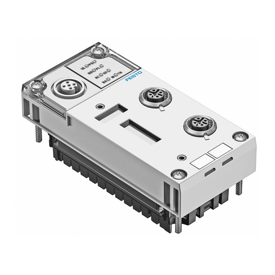
Network connections X1 and X2 Service interface for operator unit (one 4-pin M12 socket each, D-coded) (CPX-MMI; V24 interface) und USB adapter (for CPX-FMT) Fig. 1/1: Connection, setting and display components on the bus node CPX-FB36 Festo P.BE-CPX-FB36-EN en 1309NH English... -
Page 23: Dismantling And Mounting Of The Bus Node
In this case parameterisation is not created automatic- ally by the higher-order system when replacing the bus node or CPX terminal during servicing. Therefore, verify which settings are required before re- • placement and restore these settings after replacement. Festo P.BE-CPX-FB36-EN en 1309NH English... - Page 24 4. Set the screws so that the self-cutting threads can be used. 5. Tighten the screws alternately in diagonally opposite sequence with a Torx screwdriver (size T10). Tightening torque:0.9…1.1 Nm. Festo P.BE-CPX-FB36-EN en 1309NH English...
-
Page 25: Setting The Dil Switches On The Bus Node
The CPX bus node contains electrostatically sensitive devices. Do not therefore touch any contacts. • Observe the handling specifications for electrostatically • sensitive devices. This will help you avoid damage to the bus node electronics. Festo P.BE-CPX-FB36-EN en 1309NH English... - Page 26 1. Place the cover carefully on the bus node. Note Make sure that the seal is seated correctly. • 2. Tighten the two mounting screws at first by hand and then with a max. tightening torque of 0.4 Nm. Festo P.BE-CPX-FB36-EN en 1309NH English...
- Page 27 Setting the operating mode and protocol Setting the diagnostics mode is required for the Remote I/O operating mode ( chapter1.2.2). Setting the data field size is required for the Remote Control- ler operating mode ( chapter1.2.3). Festo P.BE-CPX-FB36-EN en 1309NH English...
-
Page 28: Setting The Diagnostics Mode For Remote I/O
(status bits or I/O diagnostics interface), the CPX-internal I/O image can be displaced. The system controller carries out this adjustment automatic- ally. Manual manipulation, e.g. reconfiguration of the CPX terminal or manual adaptation of the hardware and network configuration are not required. 1-10 Festo P.BE-CPX-FB36-EN en 1309NH English... -
Page 29: Setting The Data Field Size For Remote Controller
Setting the number of I/O bytes for the Remote Controller operating mode The assignment of the I/O addresses and diagnostics ad- dresses can be changed as needed by using the configuration and programming software (e.g. Rockwell RSLogix). 1-11 Festo P.BE-CPX-FB36-EN en 1309NH English... -
Page 30: Setting Ip Addressing
If all of the switches in DIL switch group 3 are set to “ON” when switching on the bus node, all IP parameters will be reset to the factory setting. Note the detailed information on addressing in sec- • tion 1.3.4. 1-12 Festo P.BE-CPX-FB36-EN en 1309NH English... -
Page 31: Connecting To The Network
Independent of the network structure, the expansion of a network segment must not exceed certain connection lengths. – Copper connecting cable: (Ethernet twisted pair cable, 22 AWG): max. 100 m between network participants 1-13 Festo P.BE-CPX-FB36-EN en 1309NH English... -
Page 32: Overview Of Connections, Network Connectors And Cables
Observe the cable specification! Bus nodes Connection technology Network connectors CPX-FB36 2 x M12 socket, D-coded, female, 4-pin, Festo connector, corresponding to IEC 61076-2 type NECU-M-S-D12G4-C2-ET Internet: www.festo.com/catalogue/ Tab. 1/5: Overview of connection technology and network plugs 1-14 Festo P.BE-CPX-FB36-EN en 1309NH English... - Page 33 If the “QuickConnect” function has been activated ( sec- tion 2.1.2 ), the crossover detection function is not avail- able. In this case the CPX-FB36 sets the pin allocation of network connection X2 to “Crossover”. Use suitable cables when the crossover detection function •...
- Page 34 1. Installation CPX-FB36 + ...D12G4... Cable specification Cable type Ethernet twisted pair cable, shielded (Shielded Twisted Pair, STP) Transmission class Category Cat 5/Cat 5e (link class) Cable diameter 6 ... 8 mm Wire cross section 0.14 ... 0.75 mm ; 22 AWG Connection length max.
-
Page 35: Network Connections Of The Cpx-Fb36
Transmitted data– 4. RX– Received data– Housing Screening, FE Tab. 1/7: Pin allocation of network connection X1 on the CPX-FB36 (M12 4-pin) Network connection X2 Connect the CPX-FB36 to the next device via connec- • tion X2. M12 socket Pin allocation... -
Page 36: Setting The Ip Address
Use Festo plugs • Seal unused interfaces ( section1.4) • 1.3.4 Setting the IP address The IP address of bus node CPX-FB36 is alternatively set via: – Dynamic addressing via DHCP/BOOTP (factory setting) – Saved network settings – Addressing via DIL switch... - Page 37 Programme “BOOTP-DHCP Server” from Rockwell Automation Saved network settings The CPX-FB36 offers the option to save the network settings in a non-volatile memory of the bus node. DHCP/BOOTP is thereby deactivated. 1. Set all switches of DIL switch group 3 to OFF Tab.
- Page 38 IP address (binary coded) If all of the switches in DIL switch group 3 are set to “ON” when switching on the bus node, all IP parameters will be reset to the factory setting. 1-20 Festo P.BE-CPX-FB36-EN en 1309NH English...
- Page 39 192.168.1 IP address - octet 4 Network mask 255.255.255.0 Gateway 0.0.0.0 1) Dynamic addressing via DHCP/BOOTP Tab. 1/10: Factory settings of the CPX-FB36 Alternatively change the first 3 octets of the IP address • via: – Operator unit CPX-MMI –...
-
Page 40: Advanced Network Settings
The following settings for the network connection can be im- plemented via Ethernet link objects ( appendixC.2.4). Automatic setting When set to the factory setting the CPX-FB36 automatically detects the baud rate and duplex mode. Baud rate Setting via attribute 6 (Forced Interface Speed) of the Ether- net link object: –... -
Page 41: Ensuring Protection Classip65/Ip67
CPX-MMI + CPX-FMT of the CPX-MMI or CPX-FMT type ISK-M12 1) if connection is not used 2) included in scope of delivery, always cover unused connection Tab. 1/11: Connections and covers for protection class IP65/IP67 1-23 Festo P.BE-CPX-FB36-EN en 1309NH English... -
Page 42: Power Supply
Observe the information on power supply ( electrical con- nection) as well as on the earthing measures to be carried out potential equalisation) contained in the CPX system de- scription. 1-24 Festo P.BE-CPX-FB36-EN en 1309NH English... -
Page 43: Preparing For Commissioning
Preparing for commissioning Chapter 2 Preparing for commissioning Festo P.BE-CPX-FB36-EN en 1309NH English... - Page 44 ......... . . 2-10 Notes on commissioning the CPX-FB36 ......
-
Page 45: Ethernet/Ip Protocol
This results in an EtherNet/IP participant receiving numerous unnecessary telegrams, which must then be discarded from the device. This can reduce the response times of the parti- cipants. The demand on the network bandwidth increases. Festo P.BE-CPX-FB36-EN en 1309NH English... -
Page 46: Quickconnect
CPX terminal and a fast connection set- up to the EtherNet/IP master. QuickConnect is commonly used for applications with a tool change, for which the downtime should be minimised by the disconnection and connection of devices. Festo P.BE-CPX-FB36-EN en 1309NH English... - Page 47 Activate QuickConnect in the PLC or in the control pro- • gram. Simplified configuration of QuickConnect on CPX-FB36: Set the CPX parameter “IP configuration” to • “With saved parameters and QuickConnect”. Selecting this setting activates QuickConnect and deactivates Auto-Negotiation for both network connections.
- Page 48 IP addresses (IP Address Con- flict Detection, ACD) is not executed completely. This can lead to multiple assigned IP addresses only being detected at a late stage. This can impair the function of the network. Festo P.BE-CPX-FB36-EN en 1309NH English...
- Page 49 CPX-8DE-8DA Digital 16-off input/output module with terminal CPX-L-8DE-8DA- strip 16-KL-3POL Analogue 2-off input module CPX-2AE-U-I (voltage/current) Analogue 2-off output module CPX-2AA-U-I (voltage/current) Analogue 4-off input module (current) CPX-4AE-I Tab. 2/1: CPX modules which support QuickConnect Festo P.BE-CPX-FB36-EN en 1309NH English...
-
Page 50: Device Level Ring Protocol (Dlr)
The Device Level Ring protocol (DLR) allows multiple devices to be operated in a ring topology. Requirements All DLR devices feature an integrated Ethernet switch with at least 2 external ports and support the DLR Protocol. Festo P.BE-CPX-FB36-EN en 1309NH English... - Page 51 • based or announce-based configuration. Operation as a ring supervisor is not possible. This func- tion is normally executed by an EtherNet/IP scanner. The DLR protocol is configured via the DLR object (class code 47 Festo P.BE-CPX-FB36-EN en 1309NH English...
-
Page 52: Modbus/Tcp Protocol
In order to configure the CPX terminal for Modbus/TCP, you will require the Modbus addresses of the data and of the I/Os of the CPX terminal ( appendix D). Addressing examples can be found in appendix D.6.1. 2-10 Festo P.BE-CPX-FB36-EN en 1309NH English... -
Page 53: Notes On Commissioning The Cpx-Fb36
Detailed instructions and further information can be found in the documentation or online help for the controller or control program. Note Bus node CPX-FB36 can be used on all EtherNet/IP or Modbus/TCP controllers. The following section describes the configuration and commissioning procedure using the example of Rockwell/Allen-Bradley controllers (PLC) via the Rockwell RSLogix software platform. -
Page 54: Switching On The Power Supply
Bus node configured and higher-order PLC is in stop mode Tab. 2/5 – Bus node configured and higher-order PLC is in run mode Tab. 2/6 Information on diagnostics using the LED displays can be found in section 4.2. 2-12 Festo P.BE-CPX-FB36-EN en 1309NH English... - Page 55 – Operating and load voltage present (in the ap- proved range) 1) Display dependent on monitoring and signal from the connected device. Tab. 2/4: Status LEDs after switching on – bus node not configured 2-13 Festo P.BE-CPX-FB36-EN en 1309NH English...
- Page 56 – Operating and load voltage present (in the approved range) 1) Display dependent on monitoring and signal from the connected device. Tab. 2/5: Status LEDs after switch on – bus node configured, PLC in stop mode 2-14 Festo P.BE-CPX-FB36-EN en 1309NH English...
- Page 57 – Operating and load voltage present (in the approved range) 1) Display dependent on monitoring and signal from the connected device. Tab. 2/6: Status LEDs after switch on – bus node configured, PLC in run mode 2-15 Festo P.BE-CPX-FB36-EN en 1309NH English...
-
Page 58: Participants In The Network
The following options are available for expanding an EDS lib- rary: – Installing EDS files – Entering participant properties manually – Importing participant properties When the CPX terminal has been registered as a potential network participant, it can be added to a network. 2-16 Festo P.BE-CPX-FB36-EN en 1309NH English... -
Page 59: Commissioning
Commissioning Chapter 3 Commissioning Festo P.BE-CPX-FB36-EN en 1309NH English... -
Page 60: Configuration
........... . 3-29 Checklist for commissioning a CPX terminal ......3-30 Festo P.BE-CPX-FB36-EN en 1309NH English... -
Page 61: Commissioning
3. Commissioning Configuration A CPX terminal with bus node CPX-FB36 can be configured using various methods. Method Description Benefits Disadvantages Configuration with EDS Installation of – With the exception – Not available with all file participant properties of the I/O data EtherNet/IP section 3.1.1... -
Page 62: Configuration With Eds File
Tab. 3/2: Configuration files for CPX-FB36 EDS- files Source www.festo.com/sp 1. Enter “CPX-FB36” in the search field. 2. Select the “Firmware and drivers” tab. 3. Click “Device description file”. 4. Select a directory and save the ZIP file. Icon files Use icon files (included in the ZIP file) to assign icons to the CPX terminal and CPX modules. - Page 63 2. Launch the EDS wizard by selecting “EDS Hardware In- stallation Tool” from the “Tools” menu. Menu command “EDS Hardware Installation Tool” Fig. 3/1: Launching the EDS wizard 3. Select the option “Register an EDS-file(s)”. Festo P.BE-CPX-FB36-EN en 1309NH English...
- Page 64 3. Commissioning Fig. 3/2: EDS wizard - Options 4. Click the “Next >” button. Fig. 3/3: EDS wizard with selected EDS file Festo P.BE-CPX-FB36-EN en 1309NH English...
- Page 65 RSLogix and the controller ( “Communications” “Go offline”). 1. In the “Controller Organizer” window of the “RSLogix 5000” program, right-click on “Ethernet” under the “I/O Configuration” branch. Fig. 3/4: Context menu in the “Controller Organizer” window Festo P.BE-CPX-FB36-EN en 1309NH English...
- Page 66 This opens the dialogue window “Select Module Type”. 3. Select the “Catalog” tab and choose the module with the description “CPX-FB36 Ethernet Module” from the bottom table. Fig. 3/5: Integrating bus node CPX-FB36 4. Confirm your selection by pressing “Create”.
- Page 67 This value can either be calculated or retrieved using CPX-FMT or a web server. The basic configuration of the CPX terminal in the project is now complete. Parameterise the modules and valve terminals used in the • CPX terminal ( chapter 3.2). Festo P.BE-CPX-FB36-EN en 1309NH English...
-
Page 68: Configuration With Generic Ethernet Module
This opens the dialogue window “Select Module Type”. 3. Select the “Catalog” tab and choose the module with the description “Generic Ethernet Module” from the bottom table. Fig. 3/6: Integrating a bus node as a Generic Ethernet Module 3-10 Festo P.BE-CPX-FB36-EN en 1309NH English... - Page 69 Fig. 3/7: “Module Properties” dialogue window 2. Enter a name for the bus node 1. 3. Select one of the following data formats from the list field “Comm Format” 5: – DATA - SINT – DATA - INT 3-11 Festo P.BE-CPX-FB36-EN en 1309NH English...
- Page 70 – 0 (standard setting) Configuration Assembly not used Remote For “Input” and “Output” the number of Controller inputs and outputs set on the CPX-FB36: – for data format SINT: in bytes – for data format INT: in words chapter 1.2.3, Tab. 1/3) For “Configuration”:...
- Page 71 Product code (depends on operating mode) – Remote I/O 14026 = 36CA – Remote Controller 14027 = 36CB Major Revision Input size / output size Depends on CPX equipment Tab. 3/5: Participant properties - Part 1 3-13 Festo P.BE-CPX-FB36-EN en 1309NH English...
- Page 72 Participant properties - Part 2 This basic configuration of the CPX terminal in the network is now complete. Information about parameterisation of the modules and valve terminals used in the CPX terminal can be found in chapter 3.2. 3-14 Festo P.BE-CPX-FB36-EN en 1309NH English...
-
Page 73: Configuration With Cpx-Fmt
3. Commissioning 3.1.3 Configuration with CPX-FMT With the help of the CPX Festo Maintenance Tool (CPX-FMT) it is possible to export the configuration and complete paramet- erisation of a CPX terminal to a file. This file can then be imported as an RSLogix project. - Page 74 3. Click “Open”. 4. Select the directory and name of the file to be imported. 5. Click “Import”. The CPX-FMT file is imported into a new RSLogix project (.ACD) as an Ethernet module. 3-16 Festo P.BE-CPX-FB36-EN en 1309NH English...
- Page 75 CPX-FMT appears in the “RSLogix 5000” program as a new Ethernet module. To integrate this module into an existing RSLogix project: 1. Right-click on the Ethernet module and select the “Copy” command from the context menu. Fig. 3/9: Copy the Ethernet module 3-17 Festo P.BE-CPX-FB36-EN en 1309NH English...
- Page 76 The basic configuration and parameterisation of the CPX ter- minal in the network is now complete. To change the parameterisation of the modules and valve terminals used in the CPX terminal, use the “RSLogix” pro- gram. 3-18 Festo P.BE-CPX-FB36-EN en 1309NH English...
-
Page 77: Configuration In The Remote Controller Operating Mode
3.1.4 Configuration in the Remote Controller operating mode When using a CPX-FEC or CPX-CEC in your CPX terminal, the CPX-FB36 is to be used as the Remote Controller. In principle, the bus node is configured in the same manner as in the Remote I/O operating mode, but with different I/O data lengths. -
Page 78: Setting Up A Listen-Only Connection
Benefit Assembly Instance Size Input Number of inputs set on the bus node Output Configura- 102 (Configuration tion Assembly) Tab. 3/7: Properties for “Connection parameters” 6. Enter the IP address of the bus node. 3-20 Festo P.BE-CPX-FB36-EN en 1309NH English... -
Page 79: Parameterisation
• nobody is within the sphere of influence of moving parts of your system. Parameterisation of the CPX-FB36 influences the behaviour of the CPX terminal. The CPX terminal is supplied from the factory with preset parameters. These parameters are saved in the bus node. -
Page 80: Parameterisation When Switching On (System Start)
The parameterisation saved in the bus node can be overwrit- ten accidentally by the controller. Prevent this by changing the “Configuration” connection • parameter using the “RSLogix” programme. 3-22 Festo P.BE-CPX-FB36-EN en 1309NH English... - Page 81 4. Close the “Module Properties” dialogue window by press- ing “Finish >>”. The setting “System start with saved parameters” is indicated by the permanent illumination of the M-LED on the bus node after the system has started. 3-23 Festo P.BE-CPX-FB36-EN en 1309NH English...
- Page 82 Use the command “Load set- tings...” in the CPX menu. 3. Enable all settings in the “Load” window and start the transfer to the bus node by pressing “OK”. 3-24 Festo P.BE-CPX-FB36-EN en 1309NH English...
-
Page 83: Methods Of Parameterisation
1) It is possible to copy the current parameterisation with the help of the CPX-MMI operator unit. Tab. 3/8: Methods of parameterisation Further information about parameterisation can be found in the CPX system description (P.BE-CPX-SYS...). 3-25 Festo P.BE-CPX-FB36-EN en 1309NH English... -
Page 84: Parameterisation Via Configuration Data
Messaging”. The addresses of the EtherNet/IP object model that are required for this can be found in Appendix C.1. Further information on programming this data transmission can be found in the manual for your controller. 3-26 Festo P.BE-CPX-FB36-EN en 1309NH English... -
Page 85: Parameterisation Using Cpx-Fmt And System Start With Saved Parameters
CPX-FMT and transfer of all parameters to the “RSLogix” program ( section 3.1.3). The parameterisation of the CPX terminal is saved directly in the CPX-FB36. To use this parameterisation the “System start” parameter needs to be set to “Saved parameters” section 3.2.1). 3-27... -
Page 86: Reaction Of The Outputs In The Fail Safe Or Idle Mode
You can determine the status to be assumed for each output channel (output or solenoid coil) separately. The standard setting is “Reset of the output channel”. Further information can be found in the CPX system descrip- tion ( P.BE-CPX-SYS-...). 3-28 Festo P.BE-CPX-FB36-EN en 1309NH English... - Page 87 3. Commissioning Web server A web server is integrated in the bus node CPX-FB36. The web server makes available the most important parameters and diagnostic functions. Fig. 3/12: Web server of the CPX-FB36 Procedure 1. Open an Internet browser of your choice on a PC that is connected to the network.
-
Page 88: Checklist For Commissioning A Cpx Terminal
Use spot checks if necessary to check the parameterisa- • tion, either with a configuration program (e.g. RSLogix) or with an operator unit (e.g.B. CPX-MMI). 3-30 Festo P.BE-CPX-FB36-EN en 1309NH English... - Page 89 Diagnostics Chapter 4 Diagnostics Festo P.BE-CPX-FB36-EN en 1309NH English...
- Page 90 ..........4-17 Festo P.BE-CPX-FB36-EN en 1309NH English...
-
Page 91: Diagnostics
Fast “On-site” error detection Operator unit the operator convenient and menu-driven description unit display of diagnostic information. Tab. 4/1: Diagnostics options Note Observe that the diagnostic information displayed de- pends on the parameterisation of the CPX terminal. Festo P.BE-CPX-FB36-EN en 1309NH English... -
Page 92: Diagnostics Via Leds
The meaning of the LEDs on the electric modules can be found in the description for the relevant module. LEDs at the bus node CPX-FB36 The LEDs on the cover indicate the operating status of the CPX bus node. - Page 93 – TP1/2 The SF LED does not il- luminate: – SF M-LED 1) Steady light: Ready for data transmission Flashing: Data transmission ongoing 2) Only illuminates when starting with saved parameters Tab. 4/2: Normal operating status Festo P.BE-CPX-FB36-EN en 1309NH English...
-
Page 94: Cpx-Specific Leds
CPX terminal can be suppressed using the “Monitoring” system parameter (function no. 4401). parameter “Monitoring CPX module”) is not Monitoring that is set separately for each module ( affected by this system parameter. Tab. 4/3: LED display PS (Power System) Festo P.BE-CPX-FB36-EN en 1309NH English... - Page 95 Error class 1 (minor error): 1 * flash, pause time Error class 2 (error): 2 * flashes, pause time Error class 3 (severe error): 3 * flashes, pause time Tab. 4/5: LED display SF (system error) - Part 1 Festo P.BE-CPX-FB36-EN en 1309NH English...
- Page 96 1) The display of the Force function (LED flashing) has precedence over the display of the setting for system start (LED illuminated). Tab. 4/7: LED display M (Modify) - Part 1 Festo P.BE-CPX-FB36-EN en 1309NH English...
-
Page 97: Network-Specific Leds
4402). LED flashes – Network settings have – Restart CPX-FB36 (Power OFF/ON), been modified section 1.3.4) 1) The display of the Force function (LED flashing) has precedence over the display of the setting for system start (LED illuminated). -
Page 98: Protocol-Specific Leds
Network status when using the EtherNet/IP protocol LED NS Sequence Status Significance/error handling • The CPX terminal is offline Check network connection Does not illuminate Tab. 4/11: LED display NS (network status) for EtherNet/IP protocol - Part 1 4-10 Festo P.BE-CPX-FB36-EN en 1309NH English... - Page 99 LED MS Sequence Status Significance/error handling Not ready for Modbus connec- – tions Is off Ready for Modbus connections – Illuminates green Tab. 4/13: LED display MS (module status) for Modbus/TCP protocol - Part 1 4-11 Festo P.BE-CPX-FB36-EN en 1309NH English...
-
Page 100: Diagnostics Via Status Bits
1-signal: Diagnostic information Description with logic 1 Error at valve Module type in which an error has occurred Error at output Error at input Tab. 4/15: Overview of status bits - Part 1 4-12 Festo P.BE-CPX-FB36-EN en 1309NH English... -
Page 101: Diagnostics Via I/O Diagnostic Interface
CPX system description. Diagnostics via I/O diagnostic interface For the bus node CPX-FB36, access to the EtherNet/IP Ob- jects through Explicit Message programming is in principle more appropriate than the use of the I/O diagnostic interface section C.1). - Page 102 Status of diagnostic – Number of entries in the diagnostic memory memory – Operating mode Diagnostic memory data – Long-term memory – Detail diagnostics + relative time stamp per error event Tab. 4/17: Diagnostic data 4-14 Festo P.BE-CPX-FB36-EN en 1309NH English...
-
Page 103: Diagnostics Via Ethernet/Ip
(max. 40 entries) – Detail diagnostics + relative time stamp per error event Diagnostic Trace Status Object – Number of entries in the diagnostic memory – Trace status Tab. 4/18: Diagnostic data with Explicit Messaging 4-15 Festo P.BE-CPX-FB36-EN en 1309NH English... -
Page 104: Diagnostics Via Modbus Tcp
The CPX system enables diagnostics via the Modbus/TCP protocol. – Diagnostics is implemented via the CPX status register description P.BE.CPX-FEC-..., chapter 6.2.2) – CPX diagnostic memory and I/O diagnostic interface description P.BE.CPX-FEC-..., chapter 6.2.4) 4-16 Festo P.BE-CPX-FB36-EN en 1309NH English... -
Page 105: Error Handling
PLC stop or fieldbus interruption or malfunction: – Monostable valves move to the basic position – Double-solenoid valves remain in the current position – Mid-position valves go into mid-position (pressurized, exhausted or closed, depending on valve type). 4-17 Festo P.BE-CPX-FB36-EN en 1309NH English... - Page 106 4. Diagnostics 4-18 Festo P.BE-CPX-FB36-EN en 1309NH English...
- Page 107 Technical appendix Appendix A Technical appendix Festo P.BE-CPX-FB36-EN en 1309NH English...
- Page 108 ..........Technical data, bus node CPX-FB36 .
- Page 109 General General technical data CPX system description P.BE-CPX-SYS-... Protection class to EN 60529 IP65 / IP67 CPX-FB36 completely mounted, plug connector according to accessories, plugged in or equipped with protective cap. Protection against electric shock (Protection against direct and indirect...
- Page 110 Remote I/O operating mode: 64 bytes each for inputs and (Input/Output-Size) outputs Remote Controller operating mode: 8/16 bytes each for inputs and outputs (dependent on the DIL switch position section 1.2.3) Tab. A/2: Technical data - communication Festo P.BE-CPX-FB36-EN en 1309NH English...
- Page 111 Address assignment of the CPX terminal Appendix B Address assignment of the CPX terminal Festo P.BE-CPX-FB36-EN en 1309NH English...
- Page 112 ........... . B-14 Address assignment after extension/conversion ..... . B-22 Festo P.BE-CPX-FB36-EN en 1309NH English...
- Page 113 Tab. B/9 provide help with this. Use the configuration documents, the operator unit (CPX- MMI) or the Festo Maintenance Tool (CPX-FMT) to determine address assignment or terminal configuration. In the operator unit display, the individual modules of the CPX terminal are displayed with the respective module identifiers.
- Page 114 The address assignment within the individual CPX I/O modules can be found in the description for the I/O module (P.BE-CPX-EA-...). Details on the CP interface can be found in the description for the CP interface (P.BE-CPX-CP-...). Festo P.BE-CPX-FB36-EN en 1309NH English...
- Page 115 4-off modules (CPX-4DE and CPX-4DA) occupy 8 I or 8 O, or 1 byte of address space (4 I/O or 4 bits of address space remain unused) Tab. B/1: Address assignment of electric CPX modules (overview; bus node in Remote I/O operating mode) – Part 1 Festo P.BE-CPX-FB36-EN en 1309NH English...
- Page 116 4-off modules (CPX-4DE and CPX-4DA) occupy 8 I or 8 O, or 1 byte of address space (4 I/O or 4 bits of address space remain unused) 3) Number of inputs switchable between 2 and 4 Tab. B/2: Address assignment of electric CPX modules (overview; bus node in Remote I/O operating mode) – Part 2 Festo P.BE-CPX-FB36-EN en 1309NH English...
- Page 117 Remote Controller operating mode 64 I 64 O 1) Module identifier in the operator unit or in the hardware configuration of the programming software Tab. B/4: Address assignment of the bus node in the Remote Controller operating mode Festo P.BE-CPX-FB36-EN en 1309NH English...
- Page 118 1 word I/1 word O or 16 inputs and 16 outputs. Pneumatic modules of type MPA-P and VPPM are ana- logue modules. Observe the order of the modules in ad- dressing or I/O mapping ( Tab. B/10). Festo P.BE-CPX-FB36-EN en 1309NH English...
- Page 119 The manuals for the pneumatic valve cluster (Midi/Maxi, CPA, MPA and VTSA/VTSA-F or ISO) contain the address assign- ment within the pneumatic modules. For further information about MPA pneumatic modules and the pneumatic interfaces: description of the CPX I/O mod- ules P.BE-CPX-EA-...). Festo P.BE-CPX-FB36-EN en 1309NH English...
- Page 120 2) Setting with rotary switch in the pneumatic interface 3) Setting with DIL switch in the pneumatic interface 4) Display text (module identifier) dependent on the version of the operator unit Tab. B/5: Overview of CPX pneumatic interfaces B-10 Festo P.BE-CPX-FB36-EN en 1309NH English...
- Page 121 2) In principle, MPA2 modules occupy 8 O (1 byte) of address space (4 O or 4 bits remain unused) Tab. B/6: Overview of CPX pneumatic modules for MPA-S and MPA-F - Part 1 B-11 Festo P.BE-CPX-FB36-EN en 1309NH English...
- Page 122 4AE-U-I 10. Number of analogue input modules CPX-4AE-T + __ x 32 I/ x 64 I + ____ I Tab. B/8: Identifying the assigned address space (total of inputs and outputs) - Part 1 B-12 Festo P.BE-CPX-FB36-EN en 1309NH English...
- Page 123 2) 4-off modules CPX-4DE and CPX-4DA as well as MPA2 pneumatic modules generally occupy 8 inputs or outputs (1 byte; available address space remains partially unused) Tab. B/9: Identifying the assigned address space (total of inputs and outputs) - Part 2 B-13 Festo P.BE-CPX-FB36-EN en 1309NH English...
- Page 124 CP interface, Front End Controller CPX-FEC Digital modules Modules with digital inputs/outputs 1) Depending on the setting, this address range can also be occupied by status bits ( Note above and Tab. 1/2). Tab. B/10: Sequence of addressing B-14 Festo P.BE-CPX-FB36-EN en 1309NH English...
- Page 125 These Assembly Instances are used for the INT format: – Inputs: Assembly Instance 111 – Outputs: Assembly Instance 110 Note Make sure that the two output assemblies 100 and 110 • are not accessed simultaneously. B-15 Festo P.BE-CPX-FB36-EN en 1309NH English...
- Page 126 CPX terminal in Fig. B/1: Module Module Input address Output address Bus node CPX-FB36 – – Digital 8-input module CPX-8DE I0 ... I7 – Tab. B/11: Addressing of example terminal 1 - Part 1 ( Fig. B/1) B-16 Festo P.BE-CPX-FB36-EN en 1309NH English...
- Page 127 MPA2 pneumatic module (4DO) – O24 ... O31 MPA2 pneumatic module (4DO) – O32 ... O39 1) 8 bits occupied, 4 bits used. Tab. B/12: Addressing of example terminal 1 - Part 2 ( Fig. B/1) B-17 Festo P.BE-CPX-FB36-EN en 1309NH English...
- Page 128 CPV valve terminal (16DO) on the CP Cylinder interface (string 1) CP output module (16DO) on the CP CP input module (16 DI) interface (string 4) Fig. B/2: Example terminal 2 (with CP interface) B-18 Festo P.BE-CPX-FB36-EN en 1309NH English...
- Page 129 MPA1 pneumatic module (8 DO) – O144 ... A151 MPA1 pneumatic module (8 DO) – O152 ... A159 1) 8 bits occupied, 4 bits used Tab. B/13: Addressing of example terminal 2 ( Fig. B/2) B-19 Festo P.BE-CPX-FB36-EN en 1309NH English...
- Page 130 – On the pneumatic interface set with DIL switch to 1...8 valve coils (8 DO). Module no.: 0 Bus node CPX-FB36 (with DIL 3.2 to VTSA pneumatics (type 44) ON for status bits) Pneumatic interface (set with DIL switch to 1...8 valve coils) Fig.
- Page 131 B. Address assignment of the CPX terminal Module Module Input address Output address Bus node CPX-FB36 with status bits I0 ... I15 – Digital 8-input module CPX-8DE I16 ... I23 – Digital 8-input module CPX-8DE I24 ... I31 – Digital 4-output module CPX-4DA –...
- Page 132 ( pneumatics description). – Additional interlinking blocks (VTSA) and/or manifold blocks (MPA-L) are inserted between existing ones. – Status bits or the I/O diagnostic interface are activated/ deactivated. B-22 Festo P.BE-CPX-FB36-EN en 1309NH English...
- Page 133 Module no.: 0 16DI Modified status bits deactivated Modified: Pneumatic interface (set with DIL switch to 1...16 valve coils) Modified: 8DI module replaced by 16DI module Fig. B/4: Example terminal 3 after extension/modification(compare with Fig. B/3) B-23 Festo P.BE-CPX-FB36-EN en 1309NH English...
- Page 134 O48 ... A63 DIL switch to 1 ... 16 valve coils bold = modified module 1) 8 bits occupied, 4 bits used Tab. B/15: Addressing of example terminal 3 after extension/modification ( Fig. B/4) B-24 Festo P.BE-CPX-FB36-EN en 1309NH English...
- Page 135 EtherNet/IP Objects of the CPX-FB36 Appendix C EtherNet/IP Objects of the CPX-FB36 Festo P.BE-CPX-FB36-EN en 1309NH English...
- Page 136 C. EtherNet/IP Objects of the CPX-FB36 Table of contents EtherNet/IP Objects of the CPX-FB36 ......
- Page 137 C. EtherNet/IP Objects of the CPX-FB36 Overview of Ethernet/IP objects This chapter describes the representation of the CPX terminal within the Ethernet/IP object model. Some of the information is in English even in the documentation in other languages, so that the original terms of the Ethernet/IP specification can be used uniquely.
- Page 138 1 ... 48 Force Parameter 116d ... 119d, 124d ... 127d 112d, 113d, 1 ... 48 Fail safe Parameter 120d, 121d, 128d, 129d Tab. C/2: Overview of EtherNet/IP objects of the CPX-FB36 - Part 1 Festo P.BE-CPX-FB36-EN en 1309NH English...
-
Page 139: Ethernet/Ip Objects Of The Cpx-Fb36
1 ... 48 Discrete Output Fail safe Mode Object 1 ... 48 Discrete Output Idle State Object 1 ... 48 Discrete Output Idle Mode Object Tab. C/3: Overview of EtherNet/IP objects of the CPX-FB36 - Part 2 Festo P.BE-CPX-FB36-EN en 1309NH English... - Page 140 Function Output Fail safe Mode Object 1 ... 48 Function Output Idle State Object 1 ... 48 Function Output Idle Mode Object Tab. C/4: Overview of EtherNet/IP objects of the CPX-FB36 - Part 3 Object Instances Name Comment class (dec.)
- Page 141 C. EtherNet/IP Objects of the CPX-FB36 Counting mode Applicable for the module-oriented objects in Tab. C/3 ... Tab. C/4 is: Instance number = Module number + 1 Explanation: – counting of the modules begins with 0 for the bus node –...
-
Page 142: Objects For Network Settings
C. EtherNet/IP Objects of the CPX-FB36 Objects for network settings C.2.1 Device Level Ring Object Object class: Instances: Attr. Access Description Type Network Topology: USINT 0: Linear 1: Ring Network Status: USINT 0: Normal 1: Ring Fault 2: Unexpected loop detected... -
Page 143: Qos Object
C. EtherNet/IP Objects of the CPX-FB36 C.2.2 QoS Object Object class: Instances: IEEE 802.1D/Q describes Ethernet Frames that contain an additional 32-bit header. This header contains, among other things, a VLAN ID and a prioritisation field. Attr. Access Description Type 802.1Q Tag enable... -
Page 144: Tcp/Ip Interface Object
C. EtherNet/IP Objects of the CPX-FB36 C.2.3 TCP/IP Interface Object Object class: Instances: With the TCP/IP Interface Object you can configure the net- work settings of a device. Attr. Access Description Type Status: DWORD Interface Status Configuration Capability DWORD Get/Set... - Page 145 C. EtherNet/IP Objects of the CPX-FB36 Attr. Access Description Type SelectAcd BOOL Get/Set LastConflictDetected: STRUCT of – ACDactivity USINT – RemoteMAC ARRAY of 6 USINT – ArpPDU ARRAY of 28 USINT QuickConnect BOOL Tab. C/9: Network settings with TCP/IP Interface Object -...
-
Page 146: Ethernet Link Object
C. EtherNet/IP Objects of the CPX-FB36 C.2.4 Ethernet Link Object Object class: Instances: One instance per Ethernet port. Instance 1 corresponds to Ethernet Port X1. Instance 2 corresponds to Ethernet Port X2. Via the Ethernet Link Object you can undertake extended settings for the Ethernet connection ( section 1.3.5):... -
Page 147: Objects For The I/O Connection
C. EtherNet/IP Objects of the CPX-FB36 Objects for the I/O connection C.3.1 Assembly Object Object class: Instances: The Assembly Object bundles together Attributes of various Objects, so that the exchange of data with the Objects can take place via one connection. - Page 148 C. EtherNet/IP Objects of the CPX-FB36 Remote I/O operating mode Each data range begins on the LSB (least significant bit) of a word. Instance 101: Input Within the instance “Input Assembly Object” all inputs of the CPX system are transmitted cyclically over the network by means of a communication connection.
- Page 149 C. EtherNet/IP Objects of the CPX-FB36 Instance 100: Output Within the Instance Output in the Assembly Object all outputs of the CPX system will be transmitted over the network by means of one communication connection. The following se- quence applies during transmission:...
- Page 150 C. EtherNet/IP Objects of the CPX-FB36 Instance 102: Configuration Instance 102 (Configuration) possesses the following member list: Obj. Number Entries in member list Type Configuration Array data ARRAY Tab. C/16: Instance 102 member list The I/O Objects 102 ... 107 also possess the following attrib-...
- Page 151 C. EtherNet/IP Objects of the CPX-FB36 Remote Controller operating mode Each data range begins on the LSB (least significant bit) of a word. Instance 100: Output Instance 100 (Output) possesses the following member list in the operating mode Remote Controller: Obj.
-
Page 152: Objects For System Data And Diagnosis
C. EtherNet/IP Objects of the CPX-FB36 Objects for system data and diagnosis C.4.1 Identity Object Object class: Instances: The Identity Object contains the identification and general information on the CPX-FB36. Service Code Reset Parameter 0 emulates a Power Cycle Parameter 1 resets the device to the factory settings and then emulates a Power Cycle. - Page 153 C. EtherNet/IP Objects of the CPX-FB36 Attr. Access Description Type Status WORD Bit 0: Owned Bit 1: reserved, shall be 0 Bit 2: Configured Bit 3: reserved, shall be 0 Bit 4-7: Extended Device Status Bit 8: Minor Recoverable Fault...
-
Page 154: Global System Object (For Operating Mode Remote I/O
C. EtherNet/IP Objects of the CPX-FB36 C.4.2 Global System Object (for operating mode Remote I/O) Object class: Instances: This Object is only available in the operating mode Remote I/O. Attr. Access Description Type Function no. CPX operating mode (bit 0 ... 3) BYTE 0 (bit 0 ... - Page 155 C. EtherNet/IP Objects of the CPX-FB36 Attr. Access Description Type Function no. Fail safe mode BYTE 1 (bit 0, 1) Specifies whether the Fail Safe mode is active or inactive. 0: inactive 1: active System Idle mode 1 (bit 2, 3) Specifies whether Idle mode is active or inactive.
- Page 156 C. EtherNet/IP Objects of the CPX-FB36 Attr. Access Description Type Function no. Get/Set Monitoring (bit 0 ... 7) BYTE 4401 (bit 0 ... 7) Bit 0: Monitoring SCS (short circuit/overload sensor supply) Bit 1: Monitoring SCO (short circuit/overload outputs) Bit 2:...
-
Page 157: Status And Diagnostics Object
C. EtherNet/IP Objects of the CPX-FB36 C.4.3 Status and Diagnostics Object Object class: Instances: The status bits and the I/O diagnostic interface are mapped here. Attr. Access Description Type Function Status bits (8 bit) BYTE 1936 Source of error: Bit 0:... -
Page 158: Diagnostics Trace Object
C. EtherNet/IP Objects of the CPX-FB36 C.4.4 Diagnostics Trace Object Object class: Instances: 1 ... 40 An instance is created for each diagnostic entry. Attr. Access Name Description Type Function no. 3488 + n Marking the first entry after BYTE... - Page 159 C. EtherNet/IP Objects of the CPX-FB36 Attr. Access Name Description Type Function no. 3488 + n Error number Possible error messages BYTE n = 10 * d + 8 System description, chapter 5 Subsequent Number of subsequent BYTE n = 10 * d + 9...
-
Page 160: Diagnostics Trace Status Object
C. EtherNet/IP Objects of the CPX-FB36 C.4.5 Diagnostics Trace Status Object Object class: Instances: Attr. Access Name Type Function Number of trace entries in the diagnostic memory BYTE 3482 (bits 0 ... 7) Status of diagnostic memory BYTE 3483 0: Recording active... - Page 161 C. EtherNet/IP Objects of the CPX-FB36 Attr. Access Name Type Function Get/Set End of error filter BYTE 3484 0: Record going errors (end of error) (filter inactive, (bit 3) presetting) 1: Do not record going errors (end of error) (filter...
-
Page 162: General Module Parameter Object
C. EtherNet/IP Objects of the CPX-FB36 C.4.6 General Module Parameter Object Object class: Instances: 1 ... 48 Applicable is: Instance number = Module number + 1 This Object enables general access to the module parameters of all existing and future CPX modules. - Page 163 C. EtherNet/IP Objects of the CPX-FB36 Attribute no. Parameter Function no. Byte Word Word 4828 + m * 64 + 0 – Parameters: Description of the respective module 4828 + m * 64 + 1 4828 + m * 64 + 2...
- Page 164 C. EtherNet/IP Objects of the CPX-FB36 Attribute no. Parameter Function no. Byte DWord DWord DWord DWord 4828 + m * 64 + 0 – – – Parameters: Description of the 4828 + m * 64 + 1 respective module 4828 + m * 64 + 2...
-
Page 165: Force Parameter
C. EtherNet/IP Objects of the CPX-FB36 C.4.7 Force parameter The first word receives the lowest instance number of the relevant Object. The second word receives the second lowest instance number, etc. Object Description Force state digital inputs Force mode digital inputs... - Page 166 C. EtherNet/IP Objects of the CPX-FB36 Composition of the Objects for Force mode Objects for Force mode: 109 , 111 , 117 , 119 , 125 , 127 Tab. C/32 ... Tab. C/34) Instances: 1 ... 48 Attr. Access Description...
- Page 167 C. EtherNet/IP Objects of the CPX-FB36 Composition of the Objects for Force state for digital I/O modules Objects for Force state: 108 , 110 Tab. C/32) Instances: 1 ... 48 Attr. Access Description Type Get/Set Value for Force state: BOOL...
- Page 168 C. EtherNet/IP Objects of the CPX-FB36 Composition of the Objects for Force state for analogue I/O modules Objects for Force state: 116 , 118 Tab. C/33) Instances: 1 ... 48 Attr. Access Description Type Get/Set Channel 0: WORD Value for Forcing...
- Page 169 C. EtherNet/IP Objects of the CPX-FB36 Composition of the Objects for Force state for technology modules Objects for Force state: 124 , 126 Tab. C/34) Instances: 1 ... 48 Attr. Access Description Type Get/Set Channel 0: BYTE Value for Forcing...
-
Page 170: Fail Safe And Idle Parameters
C. EtherNet/IP Objects of the CPX-FB36 C.4.8 Fail Safe and Idle parameters The first word receives the lowest instance number of the relevant Object. The second word receives the second lowest instance number, etc. Object Description Fail safe state digital outputs... - Page 171 C. EtherNet/IP Objects of the CPX-FB36 Object Description Fail safe state outputs technology module Fail safe mode outputs technology module Idle state outputs technology module Idle mode outputs technology module Tab. C/41: Objects for the Fail Safe and Idle parameters for...
- Page 172 C. EtherNet/IP Objects of the CPX-FB36 Composition of the Objects for Fail safe and Idle mode Objects for Fail safe mode: 113 , 121 , 129 Objects for Idle mode: , 123 , 131 Tab. C/39 ... Tab. C/41) Instances: 1 ...
- Page 173 C. EtherNet/IP Objects of the CPX-FB36 Composition of the Objects for Fail safe state and Idle state for digital output modules Objects for Fail safe state: Objects for Idle state: Tab. C/39) Instances: 1 ... 48 Attr. Access Description Type...
- Page 174 C. EtherNet/IP Objects of the CPX-FB36 Composition of the Objects for Fail safe state and Idle state for analogue output modules Objects for Fail safe state: Objects for Idle state: Tab. C/40) Instances: 1 ... 48 Attr. Access Description Type...
- Page 175 C. EtherNet/IP Objects of the CPX-FB36 Composition of the Objects for Fail safe state and Idle state for technology modules Objects for Fail safe state: Objects for Idle state: Tab. C/41) Instances: 1 ... 48 Attr. Access Description Type Get/Set...
-
Page 176: Configuration Array Object
This Object is only available in the operating mode Remote Controller. It contains the number of I/O bytes for communic- ation of theCPX-FB36 with the CPX-FEC or CPX-CEC. The set- ting is implemented via DIL switches on the CPX-FB36 Tab. 1/3). Attr. -
Page 177: Examples
C. EtherNet/IP Objects of the CPX-FB36 Examples C.5.1 Forcing inputs In this example the Force mode of an analogue input module is parameterised. Module no.: Instance no.: 1 4 AI N S PL TP1 SF TP2 M Ou t 2... - Page 178 C. EtherNet/IP Objects of the CPX-FB36 2. Define value for Force state for channel 2: Objects Force state: 116 ( Tab. C/37) Instance: Attr. Access Parameter Type Get/Set Channel 2: word Value for Forcing Number of channels BYTE All channels: values for Force mode ARRAY Tab.
- Page 179 C. EtherNet/IP Objects of the CPX-FB36 C.5.2 Parameterisation with the general Module Parameter Object In this example a signal extension time with a digital input module and a lower limit value with an analogue input mod- ule are parameterised. Module no.: Instance no.: 1...
- Page 180 C. EtherNet/IP Objects of the CPX-FB36 Attribute no. Parameter (module no. 1 in Fig. C/2) Function no. Byte Word Word 4828 + m * 64 + 0 – Monitoring the CPX module Bit 0: Behaviour after short circuit/overload 4828 + m * 64 + 1...
- Page 181 Modbus/TCP Objects of the CPX-FB36 Appendix D Modbus/TCP Objects of the CPX-FB36 Festo P.BE-CPX-FB36-EN en 1309NH English...
- Page 182 D. Modbus/TCP Objects of the CPX-FB36 Table of contents Modbus/TCP Objects of the CPX-FB36 ......
-
Page 183: Modbus/Tcp Objects Of The Cpx-Fb36
Write 40257...40264 Diagnostic memory parameters Write read device Objects objects ID0, 1, 2, 3, 4, 5 Read identification Tab. D/1: Overview of the Modbus function codes for the CPX-FB36 in the Remote I/O operating mode Festo P.BE-CPX-FB36-EN en 1309NH English... -
Page 184: Cpx Status Information (Group A
D. Modbus/TCP Objects of the CPX-FB36 CPX status information (group A) The status information provides information on the configura- tion and the fault status of the CPX terminal. It lies in the Modbus address range 45367 to 45391. Modbus CPX terminal configuration... -
Page 185: Processing Data (Groups B And D
D. Modbus/TCP Objects of the CPX-FB36 Modbus Status register address Processing data inputs Bit 15 45391 Bit 4 = 1: Operator unit connected; 0: Not connected Bit 11 = 1: Parameter write-protected; 0: No write protection Bit 15 = 1: Force active; 0: Force inactive Tab. -
Page 186: Electric Modules
D. Modbus/TCP Objects of the CPX-FB36 Modbus CPX-FB36 Remote I/O address Data from the system table Data for the system table (read access) (write access) – Module diagnostics data ( Tab. D/26) 1) n corresponds to the first Modbus address of the module. - Page 187 D. Modbus/TCP Objects of the CPX-FB36 Modbus Digital 8-off input module (CPX-8DE) address Module diagnostics data – 1) n corresponds to the first Modbus address of the module. Tab. D/9: Digital 8-off input module (CPX-8DE) - Part 2 Modbus Digital 4-off output module (CPX-4DA)
- Page 188 D. Modbus/TCP Objects of the CPX-FB36 Modbus Analogue 2-off input module (CPX-2AE) address Processing data inputs Processing data outputs Bit 15 Analogue inputs channel 0 – Analogue inputs channel 1 – Module diagnostics data – 1) n corresponds to the first Modbus address of the module.
-
Page 189: Pneumatic Modules
D. Modbus/TCP Objects of the CPX-FB36 D.4.3 Pneumatic modules Modbus Pneumatic MPA1 module type 32 (1 ... 8 valves) address Processing data inputs Processing data outputs Bit 15 Echo outputs Outputs Module diagnostics data – 1) n corresponds to the first Modbus address of the module. - Page 190 D. Modbus/TCP Objects of the CPX-FB36 Modbus Pneumatic interface for CPA pneumatics type 12 address set to 1 ... 8 valves Processing data inputs Processing data outputs Bit 15 Echo outputs Outputs Diagnostic data – 1) n corresponds to the first Modbus address of the module.
- Page 191 D. Modbus/TCP Objects of the CPX-FB36 Modbus Pneumatic interface for CPA pneumatics type 12 address set to 1 ... 22 valves Processing data inputs Processing data outputs Bit 15 Echo outputs 0 … 15 Outputs 0 ... 15 Echo outputs Outputs 16 ...
- Page 192 D. Modbus/TCP Objects of the CPX-FB36 Modbus Pneumatic interface for pneumatics type Midi/Maxi (type 03) address set to 1 ... 16 valves Processing data inputs Processing data outputs Bit 15 Echo outputs Outputs Diagnostic data – 1) n corresponds to the first Modbus address of the module.
- Page 193 D. Modbus/TCP Objects of the CPX-FB36 Modbus Pneumatic interface for pneumatics type Midi/Maxi (type 03) address set to 1 ... 32 valves Processing data inputs Processing data outputs Bit 15 Echo outputs 0 … 15 Outputs 0 ... 15 Echo outputs Outputs 16 ...
- Page 194 D. Modbus/TCP Objects of the CPX-FB36 D.4.4 Technology module CP interface The CP interface has connections for 4 strings to each of which maximum 4 CP modules can be connected. The last used string is decisive for the number of assigned bytes, even if numerically lower strings are not assigned physically.
- Page 195 D. Modbus/TCP Objects of the CPX-FB36 Modbus CPX-CP interface address used strings: 1, 2 (Line 1 ... 2) Processing data inputs Processing data outputs Bit 15 Data byte 1 Data byte 0 Data byte 1 Data byte 0 Data byte 3...
- Page 196 D. Modbus/TCP Objects of the CPX-FB36 Modbus CPX-CP interface address used strings: 1, 2, 3 (Line 1 ... 3) Processing data inputs Processing data outputs Bit 15 Data byte 1 Data byte 0 Data byte 1 Data byte 0 Data byte 3...
- Page 197 D. Modbus/TCP Objects of the CPX-FB36 Modbus CPX-CP interface address used strings 1, 2, 3, 4 (Line 1 ... 4) Processing data inputs Processing data outputs Bit 15 Data byte 1 Data byte 0 Data byte 1 Data byte 0...
-
Page 198: Composition Of Diagnostic Data (Diagnostic Word
D. Modbus/TCP Objects of the CPX-FB36 D.4.5 Composition of diagnostic data (diagnostic word) Module diagnostics data Input data Channel number (0 … 63) Fault number (0 … 255) Bit 15 and 14: 0 0: Number of the first faulty O-channel... - Page 199 D. Modbus/TCP Objects of the CPX-FB36 I/O diagnostics interface Read access Result of last request Data from the system table Result of last request: = 0: Wait = 8000 : Request successful > 8000 : Error 8001 : Write protection or operator unit has write access...
-
Page 200: Diagnostic Memory (Groups C And E
D. Modbus/TCP Objects of the CPX-FB36 Diagnostic memory (groups C and E) Modbus Diagnostic memory parameters and data address Read access Input data Bit 15 45648 Run/Stop filter 1 (CPX function number 3480) 45652 Run/Stop filter 2 (CPX function number 3484) - Page 201 D. Modbus/TCP Objects of the CPX-FB36 Modbus Diagnostic memory parameters address Write access Output data – write and modify Bit 15 40257 Run/Stop filter 1 (CPX function number 3480) 40261 Run/Stop filter 2 (CPX function number 3484) 40261 Fault end filter (CPX function number 3484)
-
Page 202: Modbus/Tcp Objects (Group F
D. Modbus/TCP Objects of the CPX-FB36 Modbus/TCP Objects (group F) Object ID Object name Table of contents Manufacturer name “Festo AG & Co. KG” Product code “CPX-FB36” MajorMinorRevision “x.y” VendorURL “http://www.festo.com” Product name “Modbus TCP” Model name “CPX-Terminal” 1) x: Version Modbus driver, y: Revision code CPX terminal Tab. -
Page 203: Addressing Examples For Modbustcp
D. Modbus/TCP Objects of the CPX-FB36 D.6.1 Addressing examples for ModbusTCP CPX terminal with digital I/O modules and MPA pneumatics CPX-FB36 MPA pneumatics Digital I/O modules Fig. D/1: Example 1: CPX terminal with digital I/O modules and MPA pneumatics D-23... - Page 204 D. Modbus/TCP Objects of the CPX-FB36 Module Loca- Modbus Input data tion address Bit 15 CPX-FB36 45392 Result of access to the I/O diagnostic interface Remote I/O 45393 Data from the system table (read access) 45394 Diagnostic data Digital 8-off input...
- Page 205 D. Modbus/TCP Objects of the CPX-FB36 Module Loca- Modbus Output data tion address Bit 15 CPX-FB36 40001 Result of access to the I/O diagnostic interface Remote I/O 40002 Data for the system table (write access) Digital 4-off out- 40003 Output data...
- Page 206 D. Modbus/TCP Objects of the CPX-FB36 CPX terminal with digital and analogue I/O modules CPX-FB36 Analogue I/O modules Digital I/O modules MPA pneumatics Fig. D/2: Example 2: CPX terminal with digital and analogue I/O modules and MPA pneumatics D-26 Festo P.BE-CPX-FB36-EN en 1309NH English...
- Page 207 D. Modbus/TCP Objects of the CPX-FB36 Module Loca- Modbus Input data tion address Bit 15 CPX-FB36 45392 Result of access to the I/O diagnostic interface Remote I/O 45393 Data from the system table (read access) 45394 Diagnostic data Digital 8-off input...
- Page 208 D. Modbus/TCP Objects of the CPX-FB36 Module Loca- Modbus Output data tion address – – CPX-FB36 40001 Result of access to the I/O diagnostic interface Remote I/O 40002 Data for the system table (write access) Analogue 2-off 40003 Analogue outputs channel 0...
- Page 209 Index Appendix E Index Festo P.BE-CPX-FB36-EN en 1309NH English...
- Page 210 ............Festo P.BE-CPX-FB36-EN en 1309NH English...
- Page 211 ....... . 4-14 Diagnostics options ......Festo P.BE-CPX-FB36-EN en 1309NH English...
- Page 212 ......IP address, Setting ......1-18 Festo P.BE-CPX-FB36-EN en 1309NH English...
- Page 213 ......1-19 Network settings, advanced ..... . 1-22 Festo P.BE-CPX-FB36-EN en 1309NH English...
- Page 214 ........1-13 Festo P.BE-CPX-FB36-EN en 1309NH English...
- Page 215 ........3-29 Festo P.BE-CPX-FB36-EN en 1309NH English...
- Page 216 E. Index Festo P.BE-CPX-FB36-EN en 1309NH English...
Need help?
Do you have a question about the CPX-FB36 and is the answer not in the manual?
Questions and answers