
Related Manuals for Festo CPX-FB38


Summary of Contents for Festo CPX-FB38
- Page 1 CPX terminal Manual Electronics CPX bus node Type CPX−FB38 Network protocol EtherCAT Manual 562 525 en 0804NH [733 639]...
- Page 3 ....... . . 562 525 © (Festo AG & Co. KG, D 73726 Esslingen, Germany, 2008) Internet: http://www.festo.com E−Mail:...
- Page 4 TÜV Süd AG, München, Germany ® TwinCAT is a registered trademark of Beckhoff Automation GmbH, Verl, Germany ® is a registered trademark of Verbands der Elektrotechnik Elektronik Informations− technik e.V., Frankfurt am Main, Germany Festo P.BE−CPX−FB38−EN en 0804NH...
-
Page 5: Table Of Contents
........1−19 Festo P.BE−CPX−FB38−EN en 0804NH... - Page 6 ......2−46 2.5.4 Parameterisation via the Festo Maintenance Tool (method 1) ..2−47 2.5.5...
- Page 7 ............B−1 Festo P.BE−CPX−FB38−EN en 0804NH...
- Page 8 Contents and general instructions Festo P.BE−CPX−FB38−EN en 0804NH...
-
Page 9: Intended Use
Extra−Low Voltage, PELV). Take into account also the general requirements for PELV circuits as per IEC/DIN EN 60204−1. Use only power packs which guarantee reliable electrical · isolation of the operating voltage as per IEC/DIN EN 60204−1. Festo P.BE−CPX−FB38−EN en 0804NH... -
Page 10: Target Group
This manual is intended exclusively for technicians trained in control and automation technology, who have experience in installing, commissioning, programming and diagnosing programmable logic controllers (PLC) and Fieldbus systems. Service Please consult your local Festo repair service if you have any technical problems. VIII Festo P.BE−CPX−FB38−EN en 0804NH... -
Page 11: Notes About The Use Of This Manual
Ethernet framework Industrial Ethernet, Switched Fast Ethernet, 100 Mbit/s Standards and norms with regard to EtherCAT: IEC 61158 IEC 61784 IEC 61918 ISO/IEC 8802−3 Further information: http://ethercat.org Tab. 0/1: Overview of CPX bus node for EtherCAT Festo P.BE−CPX−FB38−EN en 0804NH... - Page 12 An overview of the structure of the CPX terminal user documentation is contained in the CPX system manual P.BE−CPX−SYS−... Product specific information about the control system (IPC, PLC or I/O controller) can be found in the manufac turer’s product documentation. Festo P.BE−CPX−FB38−EN en 0804NH...
-
Page 13: Important User Instructions
This means that failure to observe this instruction may result in damage to property. The following pictogram marks passages in the text which describe activities with electrostatically sensitive compo nents. Electrostatically sensitive components may be damaged if they are not handled correctly. Festo P.BE−CPX−FB38−EN en 0804NH... - Page 14 Accessories: Information on necessary or sensible accessories for the Festo product. Environment: Information on environment−friendly use of Festo products. Text markings The bullet indicates activities which may be carried out in · any order. 1. Figures denote activities which must be carried out in the numerical order specified.
- Page 15 (PLC, Stand Alone operating mode) system controller (PLC, Stand Alone operating mode) field bus slave (Remote I/O operating mode) Festo Maintenance Tool (CPX−FMT); configuration and programming software for CPX modules for start−up and service purposes Handheld control unit Manual control unit (handheld control unit, CPX−MMI) for CPX modules for...
- Page 16 Programmable Logic Controller / Industrial PC Pneumatic interface The pneumatic interface is the interface between the modular electrical periphery and the pneumatics I/O diagnostic interface (system table interface) Tab. 0/3: Specific terms and abbreviations part 2 Festo P.BE−CPX−FB38−EN en 0804NH...
-
Page 17: Installation
Installation Chapter 1 1−1 Festo P.BE−CPX−FB38−EN en 0804NH... - Page 18 ........1−19 1−2 Festo P.BE−CPX−FB38−EN en 0804NH...
-
Page 19: General Instructions On Installation
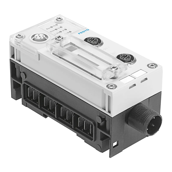
Observe the handling specifications for electrostatically · sensitive components. You avoid malfunctions of and damage to the electronics by doing so. Information about fitting the CPX terminal can be found in the CPX system manual (P.BE−CPX−SYS−...). 1−3 Festo P.BE−CPX−FB38−EN en 0804NH... - Page 20 Network connection 1 (input In1") Cover for DIL switches Service interface for the handheld control unit (V.24) Type plate *) Connecting socket: Type M12, D−coded, female, 4−pin Fig. 1/1: Connecting and display elements on the CPX bus node 1−4 Festo P.BE−CPX−FB38−EN en 0804NH...
- Page 21 T10. 2. Pull the bus node carefully and without tilting away from the contact rails of the manifold base. CPX bus node Manifold base Contact rails TORX T10 screws Fig. 1/2: Dismantling/installing the bus node 1−5 Festo P.BE−CPX−FB38−EN en 0804NH...
- Page 22 4. Tighten the screws at first only by hand. Place the screws so that the self−cutting threads can be used. 5. Tighten the screws with a TORX screwdriver size T10 with torque 0.9 1.1 Nm. 1−6 Festo P.BE−CPX−FB38−EN en 0804NH...
-
Page 23: Settings Of The Dil Switches On The Bus Node
Disconnect the power supply before removing the cover. · Make sure that the seal is seated correctly when fitting · the cover. Tighten the two fastening screws at first by hand and · then with max. 0.4 Nm. 1−7 Festo P.BE−CPX−FB38−EN en 0804NH... -
Page 24: Setting The Dil Switches
4. Replace the cover (see section 1.2.1). DIL switch 1: bus node operating mode DIL switch 2: for Remote I/O operating mode: Diagnostic mode Fig. 1/3: Settings of the DIL switches on the bus node 1−8 Festo P.BE−CPX−FB38−EN en 0804NH... - Page 25 CPX−FEC is an integral part of the CPX terminal. The FEC integrated in the terminal controls all functions. The bus node thereby takes over the connection to the EtherCAT network. Tab. 1/1: Setting the bus node operating mode with DIL switch 1 1−9 Festo P.BE−CPX−FB38−EN en 0804NH...
- Page 26 In this case, the FEC can be used for connection to other networks, for example: The FEC takes over the forwarding of incoming and outgoing data and thus behaves like an I/O module. 1−10 Festo P.BE−CPX−FB38−EN en 0804NH...
- Page 27 8−byte IO data field, e.g. with an EtherCAT controller. A superordinate controller can call up, e.g. status informa tion of the valve terminal using this interface and match or optimise the controller accordingly with other system parts. 1−11 Festo P.BE−CPX−FB38−EN en 0804NH...
- Page 28 2 bytes or 4 bytes of address space (16 I bits or 16 I/O bits; in the Status Bits mode, 8 I bits remain unused) Tab. 1/2: Setting the diagnostic mode with DIL switch 2 (Remote I/O operating mode) 1−12 Festo P.BE−CPX−FB38−EN en 0804NH...
- Page 29 The function of the DIL switch depends on the setting of the DIL switch or the set operating mode of the CPX terminal (see Tab. 1/1): In the Remote Controller operating mode, DIL switch reserved for future expansions. 1−13 Festo P.BE−CPX−FB38−EN en 0804NH...
-
Page 30: Connecting To The Network
You can obtain specifications, installation notes and instruc tions through the EtherCAT user organisation: EtherCAT Technology Group: http://www.ethercat.org/ EtherCAT−specifications (EtherCAT Specification", Profiles"), guidelines (Guidelines") and instructions (e.g. How to Configure an EtherCAT Slave Device"): http://www.ethercat.org/en/publications.html Observe the instructions there. 1−14 Festo P.BE−CPX−FB38−EN en 0804NH... - Page 31 1.3.2 Overview of connections, network connectors and cables Bus nodes Connections Network connectors Cable specification CPX−FB38 2x M12 socket, Plug from Festo, type Cable type: D−coded, female, NECU−M−S−D12G4−C2−ET, Shielded industrial Ethernet line 4−pin, according to for Ethernet lines with (at least category Cat 5) IEC 61076−2−101,...
-
Page 32: Network Interface
Pin assignment of the network interface 1.3.4 Network connection Connection with plug from Festo Connect the CPX terminal to the network with Festo plugs type NECU−M−S−D12G4−C2−ET. The plug is designed for Ethernet lines with cable diameters of 6 8 mm. - Page 33 If the CPX terminal is fitted onto the moving part of a machine, the network cable on the moving part must be provided with strain relief. Please also observe the relevant regulations in EN 60204 part 1. 1−17 Festo P.BE−CPX−FB38−EN en 0804NH...
-
Page 34: You Will Then Comply With Protection Class Ip65/Ip67
Port Port IP65/IP67 Cover IP65/IP67 L/A1, L/A2 (M12) Plug from Festo, Protective cap from Festo, type NECU−M−S−D12G4−C2−ET type ISK−M12 Service interface (M12) Connecting cable and plug of the Protective cap from Festo, handheld control unit (CPX−MMI) -
Page 35: Pin Assignment Of Power Supply
The current consumption of a CPX terminal depends on the number and type of integrated modules and components. Read the information about the power supply as well as on the earthing measures to be carried out in the CPX system manual (P.BE−CPX−SYS−...). 1−19 Festo P.BE−CPX−FB38−EN en 0804NH... - Page 36 4: Earth connection Note the specifications on the plug : Operating voltage for electronics/sensors EL/SEN Load voltage for outputs Load voltage for valves Tab. 1/6: Pin assignment for system supply, additional supply and valve supply 1−20 Festo P.BE−CPX−FB38−EN en 0804NH...
- Page 37 Commissioning Chapter 2 2−1 Festo P.BE−CPX−FB38−EN en 0804NH...
- Page 38 ......2−46 2.5.4 Parameterisation via the Festo Maintenance Tool (method 1) ..2−47 2.5.5...
-
Page 39: General Information
Parameterisation A CPX terminal in the EtherCAT network can be parameterised only with a handheld control unit (CPX−MMI) or the Festo Maintenance Tool (CPX−FMT) (no parameterization through the control system). 2−3... -
Page 40: Address Assignment
Tab. 2/7 pro vides help with this. Use the configuration documents, the handheld control unit (CPX−MMI) or the Festo Maintenance Tool (CPX−FMT) to determine address assignment or terminal set−up. In the handheld control unit, the individual modules of the CPX terminal are displayed with the respective module ident ifiers. - Page 41 The address assignment within the individual CPX I/O modules can be found in the manual for the I/O module (P.BE−CPX−EA−...). Details on the CP interface can be found in the manual for the CP interface (P.BE−CPX−CP−...). 2−5 Festo P.BE−CPX−FB38−EN en 0804NH...
- Page 42 4−way modules CPX−4DE and CPX−4DA always occupy 8 I or 8 O or 1 byte of address space (4 I/O or 8 bits of address space remain unused) Tab. 2/1: Address assignment of electric CPX modules (overview; bus node in Remote I/O operating mode) part 1 2−6 Festo P.BE−CPX−FB38−EN en 0804NH...
- Page 43 Number of inputs which can be switched between 2 and 4. Address space assignment depends on the string assignment. Tab. 2/2: Address assignment of electric CPX modules (overview; bus node in Remote I/O operating mode) part 2 2−7 Festo P.BE−CPX−FB38−EN en 0804NH...
- Page 44 8 bytes/64 O In Remote Controller operating mode Module identifier in the handheld unit or in the hardware configuration of the programming software. Tab. 2/3: Address assignment of the bus node in the Remote Controller operating mode 2−8 Festo P.BE−CPX−FB38−EN en 0804NH...
- Page 45 Note the order of the modules in addressing or I/O mapping (see Tab. 2/8). Further information about the pneumatics can be found in the corresponding pneum. descriptions (see document overview, manuals for the CPX terminal in the CPX system manual CPX−P.BE−CPX−SYS−...). 2−9 Festo P.BE−CPX−FB38−EN en 0804NH...
- Page 46 Type of electronic module used 4−way modules MPA2 always occupy 8 I (1 byte) of address space (4 I or 8 bits remain unused) Tab. 2/4: Overview of CPX pneumatic interfaces and pneumatic modules (part 1) 2−10 Festo P.BE−CPX−FB38−EN en 0804NH...
- Page 47 Module identifier in the handheld unit or in the hardware config. of the programming software Setting with DIL switch in the pneumatic interface Display text (module identifier) dependent on the version of the handheld unit Tab. 2/6: Overview of CPX pneumatic interfaces and pneumatic modules (part 3) 2−11 Festo P.BE−CPX−FB38−EN en 0804NH...
- Page 48 4−way modules CPX−4DE and CPX−4DA as well as MPA modules (MPA2 and VPPM) always occupy 8 inputs or outputs (1 byte; available address space remains partially unused) Tab. 2/7: Identifying the assigned address space (total of inputs and outputs) 2−12 Festo P.BE−CPX−FB38−EN en 0804NH...
-
Page 49: Addressing
If the 8 status bits are activated, they will occupy the first 16 inputs in the address range (8 used). If the I/O diagnostic interface is activated, it will occupy the first 16 inputs and outputs in the address range. 2−13 Festo P.BE−CPX−FB38−EN en 0804NH... - Page 50 Fig. 2/1 shows as an example a CPX terminal with MPA pneumatics and the following setting: Status bits and I/O diagnostic interface deactivated The address assignment for this example terminal (in Fig. 2/1) is shown in Tab. 2/9. 2−14 Festo P.BE−CPX−FB38−EN en 0804NH...
- Page 51 MPA2 pneumatic module (4 O) MPA2 pneumatic module (4 O) 8 bits (1 byte) assigned, 4 bits used when the Festo XML file is used, the addresses are occupied bytewise (refers to module no. 2, 5 and 6) Tab. 2/9: Addressing the example terminal 1 (see Fig.
- Page 52 Sensor CPV valve terminal (16 O) Cylinders on the CP interface (string 1) CP output module (16DO) CP input module (16DI) on the CP interface (string 4) Fig. 2/2: Example terminal 2 (with CP interface) 2−16 Festo P.BE−CPX−FB38−EN en 0804NH...
- Page 53 VSTA pneumatics as well as the following setting: Status bits activated VTSA pneumatic interface set to 1 8 valve coils (8 O) The address assignment for this example terminal (in Fig. 2/3) is shown in Tab. 2/11. 2−17 Festo P.BE−CPX−FB38−EN en 0804NH...
- Page 54 Analogue 2−output module CPX−2AA VTSA pneumatic interface set to 1 8 valve coils 16 bits assigned, 8 bits used 8 bits assigned, 4 bits used Tab. 2/11: Addressing the example terminal 3 (see Fig. 2/3) 2−18 Festo P.BE−CPX−FB38−EN en 0804NH...
-
Page 55: Address Assignment After Extension Or Conversion
In the case of module no. 1 an 8−input module has been replaced by a 16−input module. The pneumatic interface has been set to 16 outputs (16 O) in order to reserve addresses for an extension to the pneumatics. 2−19 Festo P.BE−CPX−FB38−EN en 0804NH... - Page 56 VTSA pneumatic interface with DIL switch set to 1 16 valve coils bold = changed module or changed setting 8 bits occupied, 4 bits used Tab. 2/12: Addressing the example terminal 3 after extension/conversion (see Fig. 2/4) 2−20 Festo P.BE−CPX−FB38−EN en 0804NH...
-
Page 57: Configuration
The XML file is used to identify the bus node in the EtherCAT network. Using the XML file, basic properties of the EtherCAT device as well as information concerning the manufacturer are provided to the configuration program. 2−21 Festo P.BE−CPX−FB38−EN en 0804NH... - Page 58 · program, in the Beckhoff TwinCAT System Manager in: Actions" > Import XML Descriptions..." Note You will find a detailed description of the XML file import in the subsequent section XML file import detailed information". 2−22 Festo P.BE−CPX−FB38−EN en 0804NH...
- Page 59 In the framework of importing the XML file, subsequent in formation about the bus node or the EtherCAT slave is pro vided to the configuration program. Information Description Vendor Name Festo AG & Co. KG Vendor ID 0000001Dh Product Code 00000026h Version Number 00000002h EtherCAT−Input/Output−Size 64 Byte/64 Byte...
- Page 60 Tab. 2/14: EtherCAT configuration file (XML file") for CPX terminals and bus node CPX−FB38 Download Download the current XML file onto your PLC system. · Note Check the above mentioned link casually regarding most recent version of the XML file. 2−24 Festo P.BE−CPX−FB38−EN en 0804NH...
- Page 61 ( 2 in Fig. 2/5) A file selection Pop−up window 3 opens (is displayed). 3. Select the Festo XML file 4, and click Open" 5 to confirm and cause the selection. Having completed the import of the XML file, i.e. after...
- Page 62 2. Commissioning Fig. 2/5: Registering slave properties in the configuration program (importing XML file) 2−26 Festo P.BE−CPX−FB38−EN en 0804NH...
-
Page 63: Addressing And Data Access (Data Objects)
An EtherCAT system is configured mainly by access to the object directory of the individual slaves. The access mechanism is provided by means of Service Data Objects (SDO). 2−27 Festo P.BE−CPX−FB38−EN en 0804NH... -
Page 64: Cpx Terminal Configuration Using Beckhoff Twincat
Other PLC systems may require different settings or procedures. Configuration examples presented in this section are based on the utilization of a typical office PC and the configuration and programming software package Beckhoff TwinCAT (PLC) Version 2.10. 2−28 Festo P.BE−CPX−FB38−EN en 0804NH... - Page 65 I/O Devices, as well as field bus devices or Boxes" Assignment of the I/O Devices and Boxes" to PLC projects Main functions of TwinCAT PLC Control: Configuration and programming software for TwinCAT PLC projects 2−29 Festo P.BE−CPX−FB38−EN en 0804NH...
- Page 66 Before commissioning, ensure that the connected elements (e.g. actuators) do not perform any undesired or uncontrollable movements. If necessary, disconnect the load power supply and compressed air supply. See also section 2.8, Check list for commissioning the CPX terminal. 2−30 Festo P.BE−CPX−FB38−EN en 0804NH...
- Page 67 2. Create a new project in the System Manager: File" > New" 3. Save the new project: File" > Save as..." 4. Enter a project name and confirm the input with OK or Save". 2−31 Festo P.BE−CPX−FB38−EN en 0804NH...
- Page 68 3. Except for Activate Free Run", confirm all subsequent queries with Yes (Ja"): Restart TwinCAT TwinCAT System in Config Mode" Load I/O Devices" 4. Using the right mouse button, click on the device icon, here Device 1 (EtherCAT)". A function menu opens. 2−32 Festo P.BE−CPX−FB38−EN en 0804NH...
- Page 69 EtherCAT > Advanced Settings" Typically, changes of the box properties are not required. 7. If the box properties are not displayed: Use the display function Split" to set the window partition: View" > Split" 2−33 Festo P.BE−CPX−FB38−EN en 0804NH...
- Page 70 2 in Fig. 2/6) or press [Ctrl] + [F5] to switch over to the Free Run State. The System Manager displays the activated Free Run State within the TwinCAT program window on the lower right. 2−34 Festo P.BE−CPX−FB38−EN en 0804NH...
- Page 71 Using the left mouse button, click on the symbol representing the input or output, here Valves (Example)", to display the related properties. The properties are displayed in the right area of the System Manager window. 2−35 Festo P.BE−CPX−FB38−EN en 0804NH...
-
Page 72: Linking Automation Project (Plc Project)
Example projects (Samples") and master projects (Tem plates") are available in the TwinCAT directory of your system environment or using the TwinCAT help or the TwinCAT Information System" (requires separate software installation). 2−36 Festo P.BE−CPX−FB38−EN en 0804NH... - Page 73 2. Commissioning Fig. 2/7: Linking of the EtherCAT network with a TwinCAT automation project or PLC project" (example) 2−37 Festo P.BE−CPX−FB38−EN en 0804NH...
-
Page 74: Ethercat Topology Representation
Detailed information as well as example projects and master projects can be retrieved using the following keywords: PLC", Project", Library", Sample", Configuration", Template", Tutorial" etc. For further support, please contact your Festo service, e.g. by mail: service_international@festo.com 2.4.5 EtherCAT topology representation... - Page 75 EtherCAT tab. 3. Click on Topology" 3: A separate window displays the topology of the EtherCAT network and the Devices" and Boxes", e.g. the CPX bus node and the corresponding CPX terminal 4. 2−39 Festo P.BE−CPX−FB38−EN en 0804NH...
-
Page 76: Configuration In The Remote Controller Operating Mode
To configure the CPX−FEC and CPX terminal, the use of Festo Software Tools Version 4 (FST 4) is required (see step 2.). 2. Configure the CPX terminal with the Festo Software Tools FST 4 via the CPX−FEC. 3. Start your configuration and programming software, e.g. -
Page 77: Parameterisation
2.7. Please note The CPX terminal is supplied with factory−preset parameters (default parameterisation). Please note Please observe the specific notes on parameterising the bus node CPX−FB38 in section 2.5.3. 2−41 Festo P.BE−CPX−FB38−EN en 0804NH... - Page 78 Load voltage". 2−42 Festo P.BE−CPX−FB38−EN en 0804NH...
-
Page 79: General Prerequisite For Parameterisation
In the case of CPX terminals on which the M LED lights up permanently, parameterisation will not be restored auto matically by the higher−order system upon replacement. In these cases, check before replacement to see which settings are required and carry out these settings. 2−43 Festo P.BE−CPX−FB38−EN en 0804NH... -
Page 80: Methods Of Parameterisation
Methods and description Advantages Disadvantages Method 1: Easy parameter entry Parameterisation is saved Parametrizing via the Festo guided by menu in plain locally in the CPX terminal Maintenance Tool (CPX−FMT) text and is lost if the CPX Menu−guided parameter entries via... -
Page 81: Parameterisation Via The Festo Maintenance Tool (Method 1)
2. Commissioning 2.5.4 Parameterisation via the Festo Maintenance Tool (method 1) With the PC software Festo Maintenance Tool (CPX−FMT), you can easily parameterise the CPX terminal over a USB connection. You receive the necessary USB adapter with the CPX−FMT software. - Page 82 (of the higher−level system controller). If the function System start with saved parameterisation and saved CPX expansion" is activated, the entered or changed parameter settings become valid immediately after the power supply is switched on (Power ON). 2−46 Festo P.BE−CPX−FB38−EN en 0804NH...
-
Page 83: Remarks On Parameters Of The Cpx System Settings
Reset output channel". Without parameterisation of the output channels, the following communication condition applies: Input signals are transferred. Output signals are reset (factory setting); note that for analogue outputs, the analogue value 0 is set. 2−47 Festo P.BE−CPX−FB38−EN en 0804NH... - Page 84 The status is set with the channel−specific module parameters Faul mode" and Fault state". In doing so, make sure that you assign the suitable setting to each output. Further information: see CPX system manual P.BE−CPX−SYS−... 2−48 Festo P.BE−CPX−FB38−EN en 0804NH...
-
Page 85: Cpx−Fb38−Specific Process Of Start Parameterisation During Switching On (System Start)
FEC, or from the CPX bus node. In the Festo Maintenance Tool, you will find the corresponding setting under CPX" System settings", register System parameters" System start": After the required start parameters are set, choose the system start option Saved parameters". - Page 86 The CPX−FEC loads the programmed start parameter set into the CPX bus node; the bus node then distributes the parameter set to the modules. Fig. 2/9: Sequence of start parameterisation during switch−on of a CPX terminal with bus node CPX−FB38 2−50 Festo P.BE−CPX−FB38−EN en 0804NH...
-
Page 87: Application Example For The Parameterisation
Signal extension time set to 50 ms: Reliable recording of the signals by the controller. The value of this parameter is set for the complete module but must be activated or deactivated separately for each input channel. 2−51 Festo P.BE−CPX−FB38−EN en 0804NH... -
Page 88: Checklist For Starting Up The Cpx Terminal
The CPX terminal with bus node for EtherCAT also starts with incomplete configuration. Check the configuration and address assignment of the I/Os on the CPX terminal. In order to do this, you can, if necessary, force the I/Os (see CPX system manual). 2−52 Festo P.BE−CPX−FB38−EN en 0804NH... - Page 89 Recreate the necessary hardware and network configur ation and CPX terminal parameterisation after replacement of the bus node or CPX terminal. To do this, use the EtherCAT controller or the Festo Maintenance Tool (CPX−FMT) or handheld unit (CPX−MMI). CPX−specific configuration and parameter data can be entered only with CPX−FMT or CPX−MMI.
-
Page 90: Bus Node Replacement
9. If necessary, switch the compressed air supply back on. 10. Start the program process (PLC/Master); choose the EtherCAT operating status Operational. The CPX terminal or your EtherCAT system is again in normal operating condition. 2−54 Festo P.BE−CPX−FB38−EN en 0804NH... -
Page 91: Diagnosis
Diagnosis Chapter 3 3−1 Festo P.BE−CPX−FB38−EN en 0804NH... - Page 92 ..........3−20 3−2 Festo P.BE−CPX−FB38−EN en 0804NH...
-
Page 93: Diagnosis
(P.BE−CPX−MMI−1−...) means of menus. programming Tab. 3/1: Overview of the diagnostic options of the CPX terminal 3−3 Festo P.BE−CPX−FB38−EN en 0804NH... - Page 94 Additional information on parameterisation can be found in the CPX system manual (P.BE−CPX−SYS−...) in appendix B. short circuit/overload sensor/logic provision short circuit/overload outputs (load supply) short circuit/overload valves (load supply) undervoltage outputs/valves (load supply) OUT/VA 3−4 Festo P.BE−CPX−FB38−EN en 0804NH...
- Page 95 Load voltage". 3−5 Festo P.BE−CPX−FB38−EN en 0804NH...
-
Page 96: Diagnostics Via Leds
L/A1 SF: System Failure M: Modify EtherCAT−specific LEDs Error Run: EtherCAT L/A2 operating status L/A1 Error: EtherCAT errors L/A2: Connection status (link/activity) Out2 L/A2: Connection status (link/activity) Fig. 3/1: LEDs on the CPX bus node 3−6 Festo P.BE−CPX−FB38−EN en 0804NH... - Page 97 The M LED lights or flashes if para meterisation is changed or force mode is active Only if connection is used: Constant light: connection active Flashing/blinking: Data transmission is running Tab. 3/2: Normal operating status 3−7 Festo P.BE−CPX−FB38−EN en 0804NH...
-
Page 98: Ethercat Operating Status Display (Led Run)
Bus node carries out a restart (reboot) and is not yet in the Init status (designated as Initialisation status) LED flickers One−time short flashing (1x flash, pause, 1x flash, etc.) is designated as single flash. Tab. 3/3: Fault diagnosis with the Run LED 3−8 Festo P.BE−CPX−FB38−EN en 0804NH... - Page 99 Network connection OK LED lights up Flickering: Data transmission is running LED flickers Rapid flickering seems to be lighting; the light intensity depends on the data traffic Tab. 3/5: Fault diagnosis with the LEDs L/A2, L/A1 3−9 Festo P.BE−CPX−FB38−EN en 0804NH...
-
Page 100: Fault Displays Of The Leds For System Diagnosis
2. Dependent on the parameterisation: The load voltage supply will be · LED flashes switched on again automatically after the undervoltage has been eliminated (default) Power Off/On is necessary · Tab. 3/7: Fault diagnosis with the LED PL 3−10 Festo P.BE−CPX−FB38−EN en 0804NH... - Page 101 The system error LED flashes depending on the class of error which has occurred. Error class 1 (minor error): one flash, pause Error class 2 (error): flash twice, pause Error class 3 (serious error): flash three times, pause Tab. 3/8: Fault diagnostics using the SF LED 3−11 Festo P.BE−CPX−FB38−EN en 0804NH...
- Page 102 CPX System Manual P.BE−CPX−SYS−...). LED flashes The display of the Force function (LED flashes) has priority over the display of the setting for the system start (LED lights). Tab. 3/9: Messages of the LED M 3−12 Festo P.BE−CPX−FB38−EN en 0804NH...
-
Page 103: Diagnostics Via Status Bits
Fault on output module Fault on input module Fault on analogue module or technology module Undervoltage Type of fault Short circuit/overload Wire break Other faults Tab. 3/10: Overview Status bits of the CPX bus node (optional) 3−13 Festo P.BE−CPX−FB38−EN en 0804NH... - Page 104 EtherCAT software is available to a limited extent only by means of the I/O diagnostic interface. Use the handheld unit, the Festo Maintenance Tool or your requirements according to application programs for detailed diagnostic functions.
-
Page 105: Diagnostics Via The I/O Diagnostic Interface (Sti)
Number of entries in the diagnostic memory memory Operation mode Diagnostic memory data Long−term memory Detail diagnosis + relative time stamp per fault event Tab. 3/11: Overview of diagnosis data or I/O diagnostic interface (optional) 3−15 Festo P.BE−CPX−FB38−EN en 0804NH... - Page 106 Diagnostic information or error messages of the CPX terminal are almost always only displayed in EtherCAT configuration and programming software, e.g. TwinCAT. Use the handheld unit, the Festo Maintenance Tool or your requirements according to application programs for detailed diagnostic functions.
-
Page 107: Diagnosis Via Ethercat
Diagnostics information is availabie to Beckhoff TwinCAT only to a limited extent even with activated I/O diagnosis interface. For detailed error analysis, use the handheld unit, the Festo Maintenance Tool or your requirements according to application programs for detailed diag nostic functions. -
Page 108: Fail Safe Behaviour (Fail Safe Settings)
Hard fault reaction: The controller switches to the operating mode STOP" or pre−operational when a fault occurs. Soft fault reaction: The controller switches to the operating mode RUN" or safe−operational (or possibly operational) when a fault occurs. 3−18 Festo P.BE−CPX−FB38−EN en 0804NH... - Page 109 Load voltage". 3−19 Festo P.BE−CPX−FB38−EN en 0804NH...
-
Page 110: Fault Types
Mid−position valves move to the mid−position (depending on valve type: pressurised, exhausted or blocked). 3.5.3 Fault types A listing of all error types as well as additional diagnosis information can be found in the CPX system manual (P.BE−CPX−SYS−...). 3−20 Festo P.BE−CPX−FB38−EN en 0804NH... - Page 111 Technical appendix Appendix A A−1 Festo P.BE−CPX−FB38−EN en 0804NH...
-
Page 112: A. Technical Appendix
..........A−1 Technical specifications of bus node CPX−FB38 ..... . . A−3 A−2 Festo P.BE−CPX−FB38−EN en 0804NH... - Page 113 Bus node own−current consumption from operating voltage supply for electronics/ max. 80 mA at 24 V (internal electronics) sensors (V EL/SEN Electrical isolation EtherCAT interfaces for V electrically isolated EL/SEN Power failure bridging time 10 ms A−3 Festo P.BE−CPX−FB38−EN en 0804NH...
- Page 114 Standards and norms with regard to EtherCAT: IEC 61158 IEC 61784 IEC 61918 ISO/IEC 8802−3 Further information: http://www.ethercat.org Baud rate 100 Mbit/s Cross−over recognition Auto−MDI EtherCAT input/output size 64 bytes/64 bytes, regardless of operating mode A−4 Festo P.BE−CPX−FB38−EN en 0804NH...
- Page 115 Index Appendix B B−1 Festo P.BE−CPX−FB38−EN en 0804NH...
-
Page 116: B. Index
............B−1 B−2 Festo P.BE−CPX−FB38−EN en 0804NH... - Page 117 ........1−5 B−3 Festo P.BE−CPX−FB38−EN en 0804NH...
- Page 118 ......... 3−9 Notes on the use of this manual ..... . B−4 Festo P.BE−CPX−FB38−EN en 0804NH...
- Page 119 ..... . . 1−18 Remote controller ......1−9, 2−42 B−5 Festo P.BE−CPX−FB38−EN en 0804NH...
- Page 120 ....... . . 1−19 VTSA pneumatics (ISO) ......2−9 B−6 Festo P.BE−CPX−FB38−EN en 0804NH...
Need help?
Do you have a question about the CPX-FB38 and is the answer not in the manual?
Questions and answers