Festo CPX-FB33 Electronics Description
Cpx terminal
Hide thumbs
Also See for CPX-FB33:
- Manual (160 pages) ,
- Operating instructions manual (40 pages) ,
- Brief instructions (3 pages)

Related Manuals for Festo CPX-FB33


Summary of Contents for Festo CPX-FB33
- Page 1 CPX Terminal Electronics Description CPX Bus Node Type CPX−FB33 Type CPX−M−FB34 Network protocol PROFINET IO Description 548 760 en 0812a [743 954]...
- Page 3 ....... . . 548 760 © (Festo AG & Co. KG, D 73726 Esslingen, 2008) Internet: http://www.festo.com E−Mail:...
- Page 4 Contents and general safety instructions ® ® ® ® ® ® ® PROFINET IO , PROFIBUS , SIMATIC , SPEEDCON , TORX , TÜV and VDE registered trademarks of their respective trademark holders in certain countries. Festo P.BE−CPX−PN IO−EN en 0812a...
-
Page 5: Table Of Contents
CPX terminal configuration with Siemens STEP 7 ....2−11 2.1.6 Configuration of the Fast Start−up" operating mode (FSU) ..2−39 Festo P.BE−CPX−PN IO−EN en 0812a... - Page 6 ............B−1 Festo P.BE−CPX−PN IO−EN en 0812a...
-
Page 7: Intended Use
The limit values specified for pressures, temperatures, electri cal data, torques etc. must not be exceeded. If conventional accessory components such as sensors and actuators are connected, the specified limits for pressures, temperatures, electrical data, torques etc. must not be ex ceeded. Festo P.BE−CPX−PN IO−EN en 0812a... -
Page 8: Target Group
(PLC) and fieldbus systems. Service Please consult your local Festo Service agent if you have any technical problems. Festo P.BE−CPX−PN IO−EN en 0812a... -
Page 9: Notes On The Use Of This Manual
100 Mbit/s IEC PAS 61076−3−117, IEC 61076−3−106, Guides, standards and direc IEC 60603 tives relating to PROFINET: PROFINET Installation Guide IEC 61158 IEC 61784 Further information: http://www.profinet.com Tab. 0/1: Overview of CPX bus nodes for PROFINET Festo P.BE−CPX−PN IO−EN en 0812a... - Page 10 An overview of the structure of the CPX terminal user docu mentation is contained in the CPX system description. Product−specific information about the control system (IPC, PLC or I/O controller) can be found in the manufac turer’s documentation accompanying the product. VIII Festo P.BE−CPX−PN IO−EN en 0812a...
-
Page 11: Important User Instructions
... means that failure to observe this instruction may result in damage to property. The following pictogram marks passages in the text which describe activities with electrostatically sensitive components: Electrostatically sensitive devices: incorrect handling can result in damage to components. Festo P.BE−CPX−PN IO−EN en 0812a... - Page 12 Pictograms Information: Recommendations, tips and references to other sources of information. Accessories: Information on necessary or useful accessories for the Festo product. Environment: Information on the environment−friendly use of Festo prod ucts. Text designations The bullet indicates activities which may be carried out in ·...
- Page 13 Independent system controller (PLC, Stand Alone operating mode) Installation controller (PLC, Remote Controller operating mode) Fieldbus slave (Remote I/O operating mode) Festo Maintenance Tool (CPX−FMT); configuration and programming software for CPX modules for commissioning and servicing purposes Fast Start−up, also called Prioritised Start−up; for more information see section 2.1.6...
- Page 14 < 1 ms; typical application: drive control) Programmable logic controller, also referred to as the system controller or simply controller I/O diagnostic interface (System Table Interface) Tab. 0/3: Specific terms and abbreviations part 2 Festo P.BE−CPX−PN IO−EN en 0812a...
-
Page 15: Installation
Installation Chapter 1 1−1 Festo P.BE−CPX−PN IO−EN en 0812a... - Page 16 ........1−28 1−2 Festo P.BE−CPX−PN IO−EN en 0812a...
-
Page 17: Installation
Observe the handling specifications for electrostatically · sensitive devices. You will thereby avoid operative malfunctions and damage to the electronics. Information on mounting the CPX terminal can be found in the CPX system manual (P.BE−CPX−SYS−..). 1−3 Festo P.BE−CPX−PN IO−EN en 0812a... -
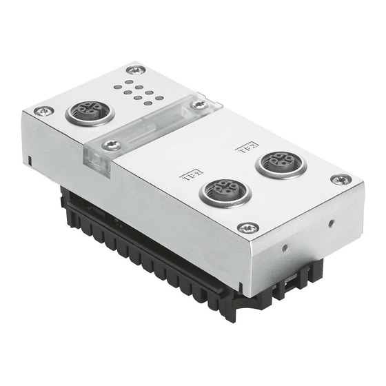
Page 18: Electrical Connection And Display Components
Fig. 1/1: Connection and display components on the CPX bus node Note Use protective caps or blanking plugs to seal unused connections. You will then comply with protection class IP65/IP67 (see section 1.7). 1−4 Festo P.BE−CPX−PN IO−EN en 0812a... -
Page 19: Dismantling And Mounting
2. Pull the bus node carefully and without tilting away from the contact rails of the interlinking block. CPX bus node (example: CPX−FB33) Interlinking block Contact rails Torx T10 screws Fig. 1/2: Dismantling/mounting of the bus node 1−5 Festo P.BE−CPX−PN IO−EN en 0812a... - Page 20 3. Push the bus node carefully into the interlinking block as far as possible. 4. Place the screws so that the existing threads can be used. 5. Tighten the screws with a Torx screwdriver size T10 to torque 0.9 ... 1.1 Nm. 1−6 Festo P.BE−CPX−PN IO−EN en 0812a...
-
Page 21: Setting The Dil Switches, Use Of The Memory Card
Disconnect the power supply before removing the cover. · When attaching, make sure that the gasket is seated · correctly. Tighten the two mounting screws hand−tight at first and · then to no more than 0.4 Nm. 1−7 Festo P.BE−CPX−PN IO−EN en 0812a... -
Page 22: Setting The Dil Switches
DIL switch (DIL 1.1 and 1.2): operating mode of the bus node DIL switch (DIL 2.1 and 2.2): only for Remote I/O operating mode: Diagnostic mode Fig. 1/3: Functions of the DIL switches on the bus node 1−8 Festo P.BE−CPX−PN IO−EN en 0812a... - Page 23 CPX−FEC is an integral part of the CPX terminal. The FEC integrated into the terminal controls all functions. The bus node acts as the interface to PROFINET. Tab. 1/1: Setting the operating mode of the bus node with DIL switch 1−9 Festo P.BE−CPX−PN IO−EN en 0812a...
- Page 24 The operating mode can be switched over to Fast Start−up" in the control software e.g. Siemens STEP 7: see Bus node selection" in section 2.1.5. A summary of all essential information can be found in section 2.1.6. 1−10 Festo P.BE−CPX−PN IO−EN en 0812a...
- Page 25 In this case, the FEC can be used as an interface to other networks, for example: the FEC handles the task of forwarding incoming and outgoing data, thus behaving like an I/O module. 1−11 Festo P.BE−CPX−PN IO−EN en 0812a...
- Page 26 8−byte IO data field, e.g. with a PROFINET controller. Using this interface, a master controller can retrieve e.g. status information for the valve terminal and can harmonise or optimise the control of other parts of the installation accordingly. 1−12 Festo P.BE−CPX−PN IO−EN en 0812a...
- Page 27 The Status Bits diagnostics mode occupies 1 byte of address space (8 I−bits) The I/O Diagnostic Interface diagnostics mode occupies 4 bytes of address space (16 I/O bits). Tab. 1/2: Setting the diagnostics mode with DIL switch (Remote I/O operating mode) 1−13 Festo P.BE−CPX−PN IO−EN en 0812a...
- Page 28 The DIL switch settings for operating mode and diagnostics mode must match the bus node selection made during the hardware and network configuration (see section 2.1.5 and the configuration example in Fig. 1/4 and Fig. 1/5). 1−14 Festo P.BE−CPX−PN IO−EN en 0812a...
- Page 29 CPX Remote Controller or CPX RC field device group (separate group, not shown in the screenshot). Fig. 1/4: Selection of the diagnostic mode in the PLC soft ware Part 1 without additional Fast Start−up" function 1−15 Festo P.BE−CPX−PN IO−EN en 0812a...
- Page 30 (FSU), select a bus node module with System Table Interface or STI mode identification from the CPX FSU field device group. Fig. 1/5: Selection of the diagnostic mode in the PLC soft ware Part 2 with additional Fast Start−up" function (FSU) 1−16 Festo P.BE−CPX−PN IO−EN en 0812a...
-
Page 31: Use Of The Memory Card
Disconnect the power supply before you insert or re · move the memory card. Replacing the The memory card is under a cover (see Fig. 1/1). You need a memory card screwdriver to remove or attach this cover. 1−17 Festo P.BE−CPX−PN IO−EN en 0812a... -
Page 32: Bus Node Replacement
9. The controller recognises the bus node using the device name on the memory card and loads all required data. Further information on the use of the memory card can be found in section 2.2.1. 1−18 Festo P.BE−CPX−PN IO−EN en 0812a... -
Page 33: Connecting To The Network
PELV power supplies or integrated power supplies with equivalent protection. Installation guidelines Installation guidelines can be obtained via the PROFINET user organisation (PNO): www.profinet.com Follow the instructions given there. 1−19 Festo P.BE−CPX−PN IO−EN en 0812a... - Page 34 HARTING: eCon2000 (IP30), eCon30xx (IP30) Phoenix Contact Factory Line series (FL ...; IP20) Siemens: SCALANCE X−100 (unmanaged), SCALANCE X−200 (managed), SCALANCE X−300 (managed), SCALANCE X−400 (modular) Examples of M12 switches: HARTING: eCon7100−B (IP65) Hirschmann: Octopus series (IP65) 1−20 Festo P.BE−CPX−PN IO−EN en 0812a...
-
Page 35: Overview Of Connection Technology, Network Plugs And Cables
Make sure that the Autonegotiation/Autocrossover" function has been activated in your control software if you are using patch and crossover cables in the same system. More instruc tions regarding this function can be found in section 2.1.5. 1−21 Festo P.BE−CPX−PN IO−EN en 0812a... - Page 36 If the CPX terminal is fitted onto the moving part of a ma chine, the network cable on the moving part must be pro vided with strain relief. Please observe also the relevant regulations in EN 60204 part 1. 1−22 Festo P.BE−CPX−PN IO−EN en 0812a...
- Page 37 Switch port, e.g. of the PLC Patch cable (crossover" pin allocation) Terminal port of an I/O device Fig. 1/6: Cabling of I/O devices for Fast Start−up" with deactivated crossover" detec tion or autonegotiation" (example configuration) 1−23 Festo P.BE−CPX−PN IO−EN en 0812a...
- Page 38 Application example: connections between devices in the control cabinet with RJ45 connection and IP65/IP67 devices with M12 connection. Examples of adapters: Lumberg: 0981 ENC 100 (RJ45/M12 adapter, M12 coupler, D−coded, mounting thread PG 9, RJ45 coupling, 90°) HARTING: eCon 6050−BA 1−24 Festo P.BE−CPX−PN IO−EN en 0812a...
-
Page 39: Network Interface Of The Cpx−Fb33
Tab. 1/4: Pin allocation of the network interfaces of the CPX−FB33 (M12) Connection with Festo plugs Connect the CPX terminal to the network with Festo plugs, type NECU−M−S−D12G4−C2−ET. The plug is designed for Ethernet cables with diameter 6 ... 8 mm. -
Page 40: Network Interface Of The Cpx−M−Fb34
Tab. 1/5: Pin allocation of the network interfaces of the CPX−M−FB34 (RJ45) Connection with Festo plugs Connect the CPX terminal to the network with Festo plugs, type FBS−RJ45−PP−GS. The plug is designed for Ethernet cables with diameter 5 ... 8 mm. - Page 41 Service interface (M12) Connecting cable and plug Festo protective cap, for the handheld type ISK−M12 If connection is not used Included in scope of delivery Tab. 1/6: Connections and covers for protection class IP65/IP67 1−27 Festo P.BE−CPX−PN IO−EN en 0812a...
-
Page 42: Pin Allocation Of Power Supply
The current consumption of a CPX terminal depends on the number and type of integrated modules and components. Read the information on power supply as well as on the earthing measures to be carried out in the CPX system man ual (P.BE−CPX−SYS...). 1−28 Festo P.BE−CPX−PN IO−EN en 0812a... - Page 43 4: Earth terminal Note the specifications on the plug. : Operating voltage for electronics/sensors EL/SEN Load voltage for outputs Load voltage for valves Tab. 1/7: Pin assignment for system supply, additional supply and valve supply 1−29 Festo P.BE−CPX−PN IO−EN en 0812a...
- Page 44 1. Installation 1−30 Festo P.BE−CPX−PN IO−EN en 0812a...
- Page 45 Commissioning Chapter 2 2−1 Festo P.BE−CPX−PN IO−EN en 0812a...
- Page 46 ..... 2−56 Check list for commissioning the CPX terminal ..... . . 2−57 2−2 Festo P.BE−CPX−PN IO−EN en 0812a...
- Page 47 (in contrast to the blockoriented addressing of other field bus systems). The controller uses the following for addressing: IP addresses and MAC IDs Fieldbus device names, called device names" for short 2−3 Festo P.BE−CPX−PN IO−EN en 0812a...
- Page 48 1 byte I (I: CPX−8DE) Digital 8−input module with chan 8DI−D 1 byte I nel diagnosis (I: CPX−8DE−D) Tab. 2/1: Overview of electric CPX modules (bus nodes in Remote I/O operating mode) part 1 2−4 Festo P.BE−CPX−PN IO−EN en 0812a...
- Page 49 (CPI: .. Byte I/.. Byte O) last used string: Per string: 4 bytes I (32 inputs) 4 bytes O (32 outputs) Tab. 2/2: Overview of electric CPX modules (bus nodes in Remote I/O operating mode) part 2 2−5 Festo P.BE−CPX−PN IO−EN en 0812a...
- Page 50 In the handheld, the bus node is always designated as FB33−RC ProfiNet I/O bus node" or FB34−RC ProfiNet RJ45 bus node" Tab. 2/4: Configuration of the bus node for the Remote Controller operating mode 2−6 Festo P.BE−CPX−PN IO−EN en 0812a...
- Page 51 Pneumatic modules of type MPA2 each occupy 8 bits of outputs, but only 4 bits are used. Additional about the pneumatics can be found in the corresponding descriptions of pneumatics. 2−7 Festo P.BE−CPX−PN IO−EN en 0812a...
- Page 52 (VI: CPX type 32: 1−4V..) MPA2 pneumatic module (type MPA2G 1 byte O 32/33) with galvanic isolation (VI: CPX type 32−G: 1−4V..) Module identifier in the Handheld Tab. 2/6: Overview of MPA pneumatic modules 2−8 Festo P.BE−CPX−PN IO−EN en 0812a...
- Page 53 The installation of the GSDML file is described on the follow ing pages. Icon files Icon files for Festo CPX terminals for displaying the CPX ter minal in your configuration software can be found at the web site address mentioned above. The integration of these icon files is described on the following pages.
- Page 54 Tab. 2/2: Compatibility of GSDML file and control The latest GSDML file for CPX terminals can be found on the Festo website. If you have any questions or technical prob lems, please contact your local Festo service or the Festo tele phone hotline. 2−10...
- Page 55 Control software: Siemens STEP 7 V. 5.4 with Service Pack SP 4 For information on other variants, please refer to the docu mentation for your controller and control software. If you have any technical problems, please consult the 2−11 Festo P.BE−CPX−PN IO−EN en 0812a...
- Page 56 2. Commissioning relevant manufacturer first. If in doubt, your local Festo service will be happy to help you further. Note Various configuration programs are available for use in conjunction with a Siemens PLC. Please observe the rel evant procedure for your configuration program.
- Page 57 4. Select the controller used (PLC/master): Insert > Station > ... (e.g. SIMATIC 300 Station). 5. Open the project by clicking on the plus symbol (on the left next to the project icon and the project name). 2−13 Festo P.BE−CPX−PN IO−EN en 0812a...
- Page 58 The child window symbolises the rack rail (mounting rail) of your control system. This child window is where you compile the individual elements of your controller, thus forming the basis for your PROFINET automation system. 2−14 Festo P.BE−CPX−PN IO−EN en 0812a...
- Page 59 6. Add your CPU and a PROFINET IO system to the hardware configuration: drag the corresponding catalogue el ements (icons) into the rack rail window ( 3 or 4 in Fig. 2/7). 2−15 Festo P.BE−CPX−PN IO−EN en 0812a...
- Page 60 Options > Update Catalog. All available CPX modules are displayed in the hardware catalogue under PROFINET IO > Additional Field Devices > Valves > Festo CPX−Terminal. You can start the selection and configuration of your modules. 2−16 Festo P.BE−CPX−PN IO−EN en 0812a...
- Page 61 This device name is also stored on the bus node’s memory card (if there is one inserted). 5. Enter a device name in the Device Name" field (e.g. CPX or CPX01) and confirm the entry by clicking Assign Name". 2−17 Festo P.BE−CPX−PN IO−EN en 0812a...
- Page 62 Fig. 2/8: Station selection with Siemens STEP 7 HW Config 2. If the hardware catalogue is not open: Click the catalogue icon ( 1 in Fig. 2/8) or use the key combination [Ctrl] + [K]. The hardware catalogue is displayed. 2−18 Festo P.BE−CPX−PN IO−EN en 0812a...
- Page 63 4. Select the station icon which corresponds to your applica tion, e.g. CPX FSU" for Fast Start−up operating mode. Fig. 2/9: Station selection typical selection on Festo CPX terminals for the various operating modes 5. Drag the corresponding CPX" station icon onto the bus line of the PROFINET IO system ( 2 in Fig.
- Page 64 IP address or the MAC−ID for addressing (information about addressing can be found in the following steps). If you assigned a device name in the course of identifying the CPX terminal, you can skip the next step. 2−20 Festo P.BE−CPX−PN IO−EN en 0812a...
- Page 65 7. Enter a unique device name for the CPX terminal in the Device Name" or Name" field ( 1 in Fig. 2/10 or 1 in Fig. 2/11, e.g. CPX−01, Station−xy or an application− specific name). 2−21 Festo P.BE−CPX−PN IO−EN en 0812a...
- Page 66 This operating mode enables faster system start−up times. Prioritised Start−up" is also called Fast Start−up" (abbre viated FSU). If you do not want to use Fast Start−up", you can skip steps 8. to 20. 2−22 Festo P.BE−CPX−PN IO−EN en 0812a...
- Page 67 8. Check the box for Prioritized startup" 2 in the Activating Fast Start−up" Properties CPX" window (see Fig. 2/11). 9. Select the IO Cycle" tab ( 1 in Fig. 2/12). Fig. 2/12: Fast Start−up" settings adaptation of the I/O cycle time (update time) 2−23 Festo P.BE−CPX−PN IO−EN en 0812a...
- Page 68 2 in Fig. 2/19). 14. Double click the configuration row for the connection (port) X1 TP1". The Properties CPX FSU Port 1" window is displayed (see Fig. 2/13). 15. Select the Options" tab (1 in Fig. 2/13). 2−24 Festo P.BE−CPX−PN IO−EN en 0812a...
- Page 69 (Disable Autonegotiation) 16. Make sure that the following is set as the Transmission medium" for Connection" 2: TP / ITP 100 Mbps full duplex" 17. Disable crossover detection 3: Check the box for Disable Autonegotiation". 2−25 Festo P.BE−CPX−PN IO−EN en 0812a...
- Page 70 ( 1 in Fig. 2/14). Select the Addresses" tab for IP addressing ( 1 in Fig. 2/15). The Addresses" tab or the Properties Ethernet interface CPX" window is displayed (see Fig. 2/16 or Fig. 2/17). 2−26 Festo P.BE−CPX−PN IO−EN en 0812a...
- Page 71 Fig. 2/14: CPX terminal properties addressing (part 1) Fig. 2/15: CPX terminal properties addressing (part 2) 22. Manual addressing (if required): Enter the IP address of the bus node ( 1 in Fig. 2/16 or Fig. 2/17). 2−27 Festo P.BE−CPX−PN IO−EN en 0812a...
- Page 72 2. Commissioning Fig. 2/16: CPX terminal properties addressing (part 3) Fig. 2/17: CPX terminal properties addressing (part 4) 2−28 Festo P.BE−CPX−PN IO−EN en 0812a...
- Page 73 One way of defining the addresses of the input and output ports TP1 and TP2 is to use the configuration table in the HW Config window. Fig. 2/18: CPX terminal properties MAC and IP addressing 2−29 Festo P.BE−CPX−PN IO−EN en 0812a...
- Page 74 2. Commissioning 23. Confirm your entries by clicking OK" (twice if necessary). 2−30 Festo P.BE−CPX−PN IO−EN en 0812a...
- Page 75 Fig. 2/19: CPX terminal configuration with Siemens STEP 7 HW Config 1. Start the PROFINET hardware configuration in your con figuration and programming software (e.g. HW Config in Siemens STEP 7) 2−31 Festo P.BE−CPX−PN IO−EN en 0812a...
- Page 76 \PROFINET−IO\Weitere Feldgeräte\Ventile\Festo CPX−Terminal (German language version) If the folder Valves\Festo CPXTerminal" (Ventile\ Festo CPX−Terminal) is not displayed, repeat the installa tion of the device master file (GSDML; see Installing the GSDML file" section). 4. Click the icon for the CPX terminal you wish to configure in the PROFINET hardware configuration (HW Config, 1 in Fig.
- Page 77 DIL switches before selecting the cata logue element (see section 1.4.2). Ensure that the setting for operating mode and diagnos tics mode selected on the bus node matches the function of the catalogue element. 2−33 Festo P.BE−CPX−PN IO−EN en 0812a...
- Page 78 The entries for the Remote Controller operating mode can be found in the CPX Remote Controller field devices group. In this operating mode, only the bus node is as signed to the CPX terminal configuration (section 2.1.9). 2−34 Festo P.BE−CPX−PN IO−EN en 0812a...
- Page 79 CPX Remote Controller or CPX RC field device group (separate group, not shown in the screenshot). Fig. 2/20: Bus node selection in the course of the CPX terminal configuration with Siemens STEP 7 Part 1 2−35 Festo P.BE−CPX−PN IO−EN en 0812a...
- Page 80 Interface or STI mode identification from the CPX FSU field device group. Fig. 2/21: Bus node selection in the course of the CPX terminal configuration with Siemens STEP 7 Part 2 with additional Fast Start−up" function 2−36 Festo P.BE−CPX−PN IO−EN en 0812a...
- Page 81 HW Config. A change is rarely required. 1. Double click on row 0 in the configuration table. The Properties CPX" window is displayed (see Fig. 2/22). Fig. 2/22: Changing the diagnostics address with Siemens STEP 7 HW Config 2−37 Festo P.BE−CPX−PN IO−EN en 0812a...
- Page 82 (The available address range depends on the controller used see manufacturer documentation.) 4. Confirm your entry with OK". The modified address is displayed in the configuration table. Additional information on diagnostics: Section 3.5, Diagnostics via PROFINET 2−38 Festo P.BE−CPX−PN IO−EN en 0812a...
- Page 83 Pay special attention to Tab. 2/2 regarding the hardware, firmware and software requirements Tab. 2/2 also contains information regarding the GSDML file required: for Fast Start−up" you need version 2.2 (or any higher version), e.g. GSDML−V2.2−Festo− CPX−20081015.xml. The installation of the GSDML file is described in section 2.1.5.
- Page 84 Activation/switchover The operating mode can be switched over to Fast Start−up" in the control software e.g. Siemens STEP 7: see section 2.1.5, Bus node selection". Additional information: Section 2.1.5, Activating Fast Start−up" 2−40 Festo P.BE−CPX−PN IO−EN en 0812a...
- Page 85 CP−EL input module (32E) (module no. 3) and MPA1 pneumatics Sensor CP−CL output module (4O) on Cylinder CP string 4 MPA−CPI valve terminal on CP string 1 Fig. 2/23: CPX example terminal with CP interface 2−41 Festo P.BE−CPX−PN IO−EN en 0812a...
- Page 86 MPA1 pneumatic module (VI: CPX type 32: 1−8V..) MPA1 pneumatic module (VI: CPX type 32: 1−8V..) ) Passive module Tab. 2/3: Configuration and addressing for CPX example terminal (addresses used from input/output word 42 onwards) 2−42 Festo P.BE−CPX−PN IO−EN en 0812a...
- Page 87 4. Replace the bus node (mounting/dismantling: see section 1.1). 5. Insert the memory card in the new bus node. 6. Put the cover back in place (as directed in section 1.4.1). 7. Switch the power supply back on. 2−43 Festo P.BE−CPX−PN IO−EN en 0812a...
- Page 88 4. Start your configuration and programming software (e.g. Siemens STEP 7). 5. Carry out reconfiguration (hardware configuration, in STEP 7 using HW Config). 6. The controller loads all required data into the bus node. 2−44 Festo P.BE−CPX−PN IO−EN en 0812a...
- Page 89 CPX terminal configuration. 6. Perform the bus node selection (station selection) with the CPX remote controller station type (see section 2.1.5 and 1 in Fig. 2/24). The bus node is thus configured as Remote Controller. 2−45 Festo P.BE−CPX−PN IO−EN en 0812a...
- Page 90 2. Commissioning Fig. 2/24: Bus node configuration in the Remote Controller operating mode with Siemens STEP 7 HW Config 2−46 Festo P.BE−CPX−PN IO−EN en 0812a...
- Page 91 In Fast Start−up" (FSU) operating mode, the module parameters cannot be set using the control software. Use the Festo Maintenance Tool (FMT) or the handheld (MMI) to enter the required settings. System parameters can be defined using the control soft ware for all operating modes, including the FSU operating mode.
- Page 92 In the bus node system parameters (using FMT or MMI) In the system parameters of the control software (e.g. Siemens STEP 7, see Fig. 2/25) Fig. 2/25: System start in FSU operating mode System start with saved parameters" (or stored para meters") 2−48 Festo P.BE−CPX−PN IO−EN en 0812a...
- Page 93 With saved parameters: The CPX bus node distributes the parameter set saved in the bus node Fig. 2/26: Sequence of start parametrisation when the CPX terminal is switched on 2−49 Festo P.BE−CPX−PN IO−EN en 0812a...
- Page 94 The bus node then distributes the parameter set to the modules. Sequence with system start parameter = 1 [Saved Parameters]: The start parameters saved in the CPX bus node are loaded ( 2 in Fig. 2/26). 2−50 Festo P.BE−CPX−PN IO−EN en 0812a...
- Page 95 2.2.2 Parametrisation of the CPX terminal with Siemens STEP 7 Setting system parameters 1. Start the PROFINET hardware configuration in your configuration and programming software (e.g. HW Config in Siemens STEP 7) Fig. 2/27: Setting system parameters with Siemens STEP 7 2−51 Festo P.BE−CPX−PN IO−EN en 0812a...
- Page 96 CPX module monitoring are not af fected by the setting of the system parameter for monitor ing. Additional information about parametrisation can be found in the CPX system description (P.BE−CPX−SYS...) in appendix B. 2−52 Festo P.BE−CPX−PN IO−EN en 0812a...
- Page 97 The Properties ..." dialogue window is displayed. 3. Click the value of the parameter you wish to modify. A list with the possible values will be opened 2. 4. Modify the parameter by clicking the desired value. 2−53 Festo P.BE−CPX−PN IO−EN en 0812a...
- Page 98 2. Commissioning 5. End by confirming the entry. Note Module parameters can refer to: Properties of the complete module Properties of an individual channel of a module 2−54 Festo P.BE−CPX−PN IO−EN en 0812a...
- Page 99 System parameters Module parameters Diagnostics memory parameters can still be parametrised via the bus while the handheld is in use. Information on operating the handheld can be found in the description for the handheld P.BE−CPX−MMI−... 2−55 Festo P.BE−CPX−PN IO−EN en 0812a...
- Page 100 Signal extension time set to 50 ms: reliable detection of the signals by the controller. The value of this parameter is set for the complete mod ule, however it must be activated/deactivated separately for each input channel. 2−56 Festo P.BE−CPX−PN IO−EN en 0812a...
- Page 101 (see also start parametrisation in sec tion 2.2.1). Use spot checks if necessary to check the parametrisa · tion, e.g. with the configuration program or with the handheld. 2−57 Festo P.BE−CPX−PN IO−EN en 0812a...
- Page 102 2. Commissioning 2−58 Festo P.BE−CPX−PN IO−EN en 0812a...
- Page 103 Diagnostics Chapter 3 3−1 Festo P.BE−CPX−PN IO−EN en 0812a...
- Page 104 ..... 3−16 3.5.3 User−specific diagnostics with Siemens STEP 7 ....3−18 3−2 Festo P.BE−CPX−PN IO−EN en 0812a...
-
Page 105: Diagnostics
Detailed module−re lated and channel−related error detection in the on line mode of the configura tion software and in the PLC user program. Tab. 3/1: Overview of the diagnostics options of the CPX terminal 3−3 Festo P.BE−CPX−PN IO−EN en 0812a... - Page 106 3. Diagnostics Note Note that the diagnostic information shown can depend on the settings (see section 1.4.2) as well as on the parametrisation (see section 2.2) of the CPX terminal. 3−4 Festo P.BE−CPX−PN IO−EN en 0812a...
-
Page 107: Diagnostics Via Leds
CPX bus node. CPX−specific LEDs PS: Power system PL: Power load SF: System failure M: Modify PROFINET−specific LEDs NF: Network failure TP1: Link/Traffic 1 TP2: Link/Traffic 2 Fig. 3/1: LEDs on the CPX bus nodes 3−5 Festo P.BE−CPX−PN IO−EN en 0812a... - Page 108 The M LED lights up or flashes if changed parametrisation or force mode is active Only if connection is used: Steady light: connection active Flickering/flashing: data transmission is running Tab. 3/2: Normal operating status 3−6 Festo P.BE−CPX−PN IO−EN en 0812a...
-
Page 109: Network Error Display Led Nf / Connection Status Led Tp1, Tp2
(section 2.1.5) or flashing module Appears as lit in the case of fast flickering. The light intensity depends on data traffic. Tab. 3/3: Error diagnosis with the LEDs NF and TP1/TP2 3−7 Festo P.BE−CPX−PN IO−EN en 0812a... -
Page 110: Error Displays Of The Leds For System Diagnosis Ps, Pl, Sf
The load voltage supply will be · LED flashing switched on again automatically when the undervoltage has been eliminated (default) Power Off/On is necessary · Tab. 3/4: Error diagnosis with the LEDs PS and PL 3−8 Festo P.BE−CPX−PN IO−EN en 0812a... - Page 111 The system error LED flashes depending on the class of error which has occurred. Error class 1 (minor error): one flash, pause Error class 2 (error): flash twice, pause Error class 3 (serious error): flash three times, pause Tab. 3/5: Error diagnosis with the SF LED 3−9 Festo P.BE−CPX−PN IO−EN en 0812a...
- Page 112 4402, see CPX system description P.BE−CPX−SYS...). LED flashing The display of the force function (LED flashing) has priority over the display of the setting for the system start (LED lit up). Tab. 3/6: M LED signals 3−10 Festo P.BE−CPX−PN IO−EN en 0812a...
-
Page 113: Diagnostics Via Status Bits
Error at output Error at input Error on analogue module/ technology module Undervoltage Type of error Short circuit/overload Wire break Other error Tab. 3/7: Status bits of the CPX bus node (optional) 3−11 Festo P.BE−CPX−PN IO−EN en 0812a... -
Page 114: Diagnostics Via The I/O Diagnostic Interface (Sti)
1.4.2 and other explanations about configuration in section 2.1.5). Additional information can be found in the CPX system description (P.BE−CPX−SYS−...) in the section on diagnostics and error handling. 3−12 Festo P.BE−CPX−PN IO−EN en 0812a... -
Page 115: Diagnostics Via Profinet
Depending on the parametrisation, the outputs (valves and electric outputs) will be switched off (factory setting), switched on or retain their status. Further information on the Fail Safe setting can be found in the CPX system description P.BE−CPX−SYS−... 3−13 Festo P.BE−CPX−PN IO−EN en 0812a... - Page 116 Single−solenoid valves move to their initial position. Double−solenoid valves remain in their current position. Mid−position valves move to their mid position (which depends on the valve type: pressurised, exhausted or blocked). 3−14 Festo P.BE−CPX−PN IO−EN en 0812a...
- Page 117 Reserved 1029 Short circuit in the CP string (CP line) Reserved 1030 Slave has no bus connection Reserved 1031 Channel failed Bold = relevant to CPX−FB33/FB34 Tab. 3/8: Error types for diagnostics via PROFINET 3−15 Festo P.BE−CPX−PN IO−EN en 0812a...
-
Page 118: Online Diagnostics With Siemens Step
3.5.2 Online diagnostics with Siemens STEP 7 1. Start the PROFINET hardware configuration in your con figuration and programming software (e.g. HW Config in Siemens STEP 7) Fig. 3/2: Online diagnostics with STEP 7 3−16 Festo P.BE−CPX−PN IO−EN en 0812a... - Page 119 6. Click the event and then click Display" 5. The diagnostics details are displayed in a new window 6. These give you more precise information on how to pro ceed. The information is independent of the controller used. 3−17 Festo P.BE−CPX−PN IO−EN en 0812a...
-
Page 120: User−Specific Diagnostics With Siemens Step
IO device and provides this Function Blocks information as an output parameter Tab. 3/9: Intended use (meaning) of the Organisation Blocks OB 82 and OB 86 and the Function Block SFB 54 3−18 Festo P.BE−CPX−PN IO−EN en 0812a... - Page 121 Starting address of the module with alarm :=“DB_ALARM”.LEN Length of alarm information TINFO:=“DB_ALARM”.TINFO Target range for OB start information (Task information) AINFO:=“DB_ALARM”.AINFO Target range for header/additional information (Alarm information) Fig. 3/3: Program example in STL for reading diagnostics information 3−19 Festo P.BE−CPX−PN IO−EN en 0812a...
- Page 122 3. Diagnostics 3−20 Festo P.BE−CPX−PN IO−EN en 0812a...
- Page 123 Technical appendix Appendix A A−1 Festo P.BE−CPX−PN IO−EN en 0812a...
- Page 124 ........... A−5 A−2 Festo P.BE−CPX−PN IO−EN en 0812a...
- Page 125 From operating voltage supply for electronics/ Max. 120 mA at 24 V sensors (V (internal electronics) EL/SEN Galvanic isolation PROFINET interfaces to V Galvanically isolated EL/SEN (transformer 1500 V) Mains buffering time 10 ms A−3 Festo P.BE−CPX−PN IO−EN en 0812a...
- Page 126 From operating voltage supply for electronics/ Max. 120 mA at 24 V sensors (V (internal electronics) EL/SEN Galvanic isolation PROFINET interfaces to V Galvanically isolated EL/SEN (transformer 1500 V) Mains buffering time 10 ms A−4 Festo P.BE−CPX−PN IO−EN en 0812a...
- Page 127 Guides, standards and directives relating to PROFINET: PROFINET Installation Guide IEC 61158 IEC 61784 Additional information: http://www.profinet.com Transmission technology Switched Fast Ethernet Transmission rate 100 Mbit/s Crossover detection Auto−MDI PROFINET input/output size 64 bytes/64 bytes, regardless of operating mode A−5 Festo P.BE−CPX−PN IO−EN en 0812a...
- Page 128 A. Technical appendix A−6 Festo P.BE−CPX−PN IO−EN en 0812a...
- Page 129 Index Appendix B B−1 Festo P.BE−CPX−PN IO−EN en 0812a...
- Page 130 ............B−1 B−2 Festo P.BE−CPX−PN IO−EN en 0812a...
- Page 131 ......1−9 , 1−11 , 2−6 , 2−45 B−3 Festo P.BE−CPX−PN IO−EN en 0812a...
- Page 132 ....Operating mode ......1−9 , 2−45 B−4 Festo P.BE−CPX−PN IO−EN en 0812a...
- Page 133 ..... . . 1−27 Remote Controller ......1−9 , 2−45 B−5 Festo P.BE−CPX−PN IO−EN en 0812a...
- Page 134 ......1−29 VTSA pneumatics (ISO) ......2−7 B−6 Festo P.BE−CPX−PN IO−EN en 0812a...
Need help?
Do you have a question about the CPX-FB33 and is the answer not in the manual?
Questions and answers