
Related Manuals for Festo CPX-FB32


Summary of Contents for Festo CPX-FB32
- Page 1 CPX terminal Electronics Manual CPX field bus node Type CPX−FB32 Field bus protocol EtherNet/IP Manual 541 305 en 0605NH [693 135]...
- Page 3 ....... . . 541 305 © (Festo AG & Co. KG, D 73726 Esslingen, Federal Republic of Germany, 2006) Internet: http://www.festo.com...
- Page 4 Rockwell Automation SPEEDCON® is a registered trade name of PHOENIX CONTACT GmbH & Co. KG, 32825 Blomberg, Germany TORX® is a registered trade name of CAMCAR TEXTRON INC., Rockford, Ill., USA Festo P.BE−CPX−FB32−EN en 0605NH...
-
Page 5: Table Of Contents
........1−17 Festo P.BE−CPX−FB32−EN en 0605NH... - Page 6 ..........3−17 Festo P.BE−CPX−FB32−EN en 0605NH...
- Page 7 ............C−1 Festo P.BE−CPX−FB32−EN en 0605NH...
- Page 8 Contents and general instructions Festo P.BE−CPX−FB32−EN en 0605NH...
-
Page 9: Designated Use
This manual is intended exclusively for technicians trained in control and automation technology who have experience in installing, commissioning, programming and diagnosing slaves on the EtherNet. Service Please consult your local Festo repair service if you have any technical problems. Festo P.BE−CPX−FB32−EN en 0605NH... -
Page 10: Notes On The Use Of This Manual
Further information on the EtherNet/IP can be found in: www.odva.org Information on master manufacturers can be found in: www.rockwellautomation.com General basic information on the method of operation, on fitting, installing and commissioning CPX terminals can be found in the CPX system manual. VIII Festo P.BE−CPX−FB32−EN en 0605NH... -
Page 11: Important User Instructions
This means that failure to observe this instruction may result in damage to property. The following pictogram marks passages in the text which describe activities with electrostatically sensitive compo nents. Electrostatically sensitive components may be damaged if they are not handled correctly. Festo P.BE−CPX−FB32−EN en 0605NH... - Page 12 Accessories: Information on necessary or sensible accessories for the Festo product. Environment: Information on environment−friendly use of Festo products. Text markings The bullet indicates activities which may be carried out in · any order. 1. Figures denote activities which must be carried out in the numerical order specified.
- Page 13 Instructions on fitting, installing, commissioning type P.BE−CPX−FEC−... and diagnosing the CPX Front End Controller. Software FST" Programming in Statement List and Ladder package Diagram for the FEC Tab. 0/1: Manuals on the CPX terminal part 1 Festo P.BE−CPX−FB32−EN en 0605NH...
- Page 14 Midi/Maxi type P.BE−MIDI/MAXI−03−... pneumatics (type 03) Valve terminal with Instructions on fitting, installing, commission VTSA/ISO pneumatics" ing, maintaining and converting the VTSA/ISO type P.BE−VTSA−44−... pneumatics (type 44) Tab. 0/2: Manuals on the CPX terminal part 2 Festo P.BE−CPX−FB32−EN en 0605NH...
- Page 15 Common term for the CPX modules which provide digital inputs and outputs. I/Os Digital inputs and outputs OB, OW Output byte, output word Pneumatic interface The pneumatic interface is the interface between the modular electrical periphery and the pneumatics. Tab. 0/3: CPX−specific terms and abbreviations XIII Festo P.BE−CPX−FB32−EN en 0605NH...
- Page 16 Contents and general instructions Festo P.BE−CPX−FB32−EN en 0605NH...
-
Page 17: Installation
Installation Chapter 1 1−1 Festo P.BE−CPX−FB32−EN en 0605NH... - Page 18 ........1−17 1−2 Festo P.BE−CPX−FB32−EN en 0605NH...
-
Page 19: General Instructions On Installation
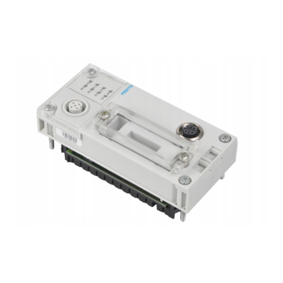
Please note Use a protective cap or blanking plug to seal unused connections. You will then comply with protection class IP65/IP67. Information on fitting the CPX terminal can be found in the CPX system manual (P.BE−CPX−SYS−...). 1−3 Festo P.BE−CPX−FB32−EN en 0605NH... - Page 20 Bus status−specific and CPX−specific Transparent cover for the DIL switches LEDs Field bus interface: Ethernet Service interface for the Handheld connection (4−pin M12 socket, (V24) D−coded) Fig. 1/1: Connecting and display elements on the CPX field bus node 1−4 Festo P.BE−CPX−FB32−EN en 0605NH...
- Page 21 3. Tighten the screws at first only by hand. Place the screws so that the self−cutting threads can be used. 4. Tighten the screws with a Torx screwdriver size T10 with torque 0.9 ... 1.1 Nm. 1−5 Festo P.BE−CPX−FB32−EN en 0605NH...
-
Page 22: Settings Of The Dil Switches On The Field Bus Node
1. Place the cover carefully on the node. Please note Make sure that the seal is seated correctly. · 2. Tighten the two fastening screws at first by hand and then with torque 0.4 Nm. 1−6 Festo P.BE−CPX−FB32−EN en 0605NH... -
Page 23: Settingthe Dil Switches
4. Fit the cover again (section 1.2.1). DIL switch 1: Operating mode DIL switch 2: Diagnostic mode or number of I/O bytes for Remote Controller DIL switch 3: IP addressing Fig. 1/3: DIL switches in the field bus node 1−7 Festo P.BE−CPX−FB32−EN en 0605NH... - Page 24 An FEC integrated in the CPX terminal takes DIL 1.2: OFF control of the I/Os. This operating mode is only useful if an FEC is integrated in the CPX terminal. Tab. 1/1: Setting the operating mode with DIL switch 1 1−8 Festo P.BE−CPX−FB32−EN en 0605NH...
- Page 25 (+ 16 I−bits (8 used)) 2.2: ON Reserved for future extensions 2.1: ON 2.2: ON The I/O diagnostic interface occupies an additional 16 I/O bits. Tab. 1/2: Setting the diagnostic mode with DIL switch 2 (operating mode Remote I/O) 1−9 Festo P.BE−CPX−FB32−EN en 0605NH...
- Page 26 16 bytes I / 16 bytes I for communication 2.1: OFF of the field bus node with the CPX−FEC 2.2: ON Reserved 2.1: ON 2.2: ON Tab. 1/3: Setting the number of I/O bytes with DIL switch 2 (operating mode Remote Controller) 1−10 Festo P.BE−CPX−FB32−EN en 0605NH...
- Page 27 (factory setting) Host ID of the IP address Tab. 1/4: Settings of DIL switch 3 for different types of addressing The factory setting is the dynamic addressing. Note the detailed information on addressing in section 1.3.3. 1−11 Festo P.BE−CPX−FB32−EN en 0605NH...
-
Page 28: Connecting The Ethernet Field Bus
Please observe also the relevant regulations in EN 60204 part 1. The specifications for Ethernet networks as per ANSI/TIA/ EIA−568−B.1 apply for the field bus length. 1−12 Festo P.BE−CPX−FB32−EN en 0605NH... -
Page 29: Field Businterface Of The Cpx−Fb32
Tab. 1/5: Pin assignment of the field bus interface of the CPX−FB32 (M12 4−pin) Connection with field bus plugs from Festo You can connect the CPX terminal to the field bus with the field bus plug from Festo (type NECU−M−S−D12G4−C2−ET, part no. -
Page 30: Setting The Ip Address
Use the network setting saved in the CPX−FB32 The CPX−FB32 offers the possibility of saving the network settings in a non−volatile memory. DHCP/BOOTP is thereby deactivated. 1. Set all switch elements of DIL switch 3 to OFF (see Tab. 1/4). 1−14 Festo P.BE−CPX−FB32−EN en 0605NH... - Page 31 Fig. 1/4: Examples of set IP addresses (binary coded) with fixed addressing The settings of the network mask and the Gateway are set with fixed addressing as follows and cannot be modified: Network mask: 255.255.255.0 Gateway: 0.0.0.0 1−15 Festo P.BE−CPX−FB32−EN en 0605NH...
-
Page 32: Extended Ethernet Settings
With the CPX Web Monitor you can load a visualization pack age on an HTLM basis into the Webserver of the FB32. User− friendly diagnostic possibilities are then available via the Ethernet network. 1−16 Festo P.BE−CPX−FB32−EN en 0605NH... -
Page 33: Pin Assignment Of Power Supply
The current consumption of a CPX terminal depends on the number and type of integrated modules and components. Read the information on power supply as well as on the earthing measures to be carried out in the CPX system manual. 1−17 Festo P.BE−CPX−FB32−EN en 0605NH... - Page 34 5: 24 V / 24 V 5: 24 V 7/8"−5POL : Operating voltage for electronics/sensors EL/SEN Load voltage for outputs Load voltage for valves Tab. 1/6: Pin assignment for system supply, additional supply and valve supply 1−18 Festo P.BE−CPX−FB32−EN en 0605NH...
-
Page 35: Commissioning
Commissioning Chapter 2 2−1 Festo P.BE−CPX−FB32−EN en 0605NH... - Page 36 ....2−32 Check list for commissioning the CPX terminal with FB32 ....2−33 2−2 Festo P.BE−CPX−FB32−EN en 0605NH...
-
Page 37: Commissioning
If you configure the CPX terminal with an EDS file, the field bus node in the first location must be installed as module 0. The CPX terminal has an address range of up to 64 bytes of inputs and 64 bytes of outputs. 2−3 Festo P.BE−CPX−FB32−EN en 0605NH... -
Page 38: Ascertaining The Address Range
Digital 8−output module CPX−8DA 8 DO Digital multi I/O module CPX−8DE−8DA 8 DI / 8 DO Module identifier in the handheld 8 bits are always assigned Tab. 2/1: Overview of electric CPX modules (part 1) 2−4 Festo P.BE−CPX−FB32−EN en 0605NH... - Page 39 Overview of electric CPX modules (part 2) The address assignment within the individual I/O modules can be found in the manual for the I/O modules. Details on the CP interface can be found in the manual for the CP inter face. 2−5 Festo P.BE−CPX−FB32−EN en 0605NH...
- Page 40 D2 Further modules in preparation Module identifier in the handheld Type of electronic module used 8 bits are always assigned Tab. 2/3: Summary of pneumatic modules and pneumatic interfaces (part 1) 2−6 Festo P.BE−CPX−FB32−EN en 0605NH...
- Page 41 The address assignment within the pneumatic modules can be found in the manual for the valve terminal pneumatics. Further information on MPA pneumatic modules can be found in the manual for the CPX I/O modules (P.BE−CPX−EA−...). 2−7 Festo P.BE−CPX−FB32−EN en 0605NH...
- Page 42 _____ O 15.Total sum of inputs/outputs to be configured Sum of 1 to 14: _____ I _____ O 8 bits are always assigned (4 remain unused). Tab. 2/5: Ascertaining the number of inputs and outputs 2−8 Festo P.BE−CPX−FB32−EN en 0605NH...
-
Page 43: Address Assignment Of The Cpx Terminal
The field bus node counts as a module with 0 inputs and 0 outputs when the status bits and the I/O diagnostic interface are deactivated. The I/Os of different module types are assigned separately from each other. The sequence in the following table then applies: 2−9 Festo P.BE−CPX−FB32−EN en 0605NH... - Page 44 Status bits and I/O diagnostic interface deactivated Module no.: 0 Field bus node CPX−FB32 MPA1 pneumatic modules (8 DO each) MPA pneumatic interface MPA2 pneumatic modules (4 DO each) Fig. 2/1: Example terminal 1 (with MPA1 and MPA2 pneumatics) 2−10 Festo P.BE−CPX−FB32−EN en 0605NH...
- Page 45 Addressing the example terminal 1 (see Fig. 2/1) If modular EDS is used, the addresses will be assigned in bytes. In the example above, the output addresses therefore change as from modules 2, 5 and 6. 2−11 Festo P.BE−CPX−FB32−EN en 0605NH...
- Page 46 CPV valve terminal (16 DO) on the Cylinder CP interface (string 1) CP output module (16 DO) on the CP input module (16 DI) CP interface (string 4) Fig. 2/2: Example terminal 2 (with CP interface) 2−12 Festo P.BE−CPX−FB32−EN en 0605NH...
- Page 47 O136 ... O143 CPX−8DE−8DA MPA1 pneumatic module (8 DO) O144 ... O151 MPA1 pneumatic module (8 DO) O152 ... O159 8 bits occupied, 4 bits used Tab. 2/8: Addressing the example terminal 2 (see Fig. 2/2) 2−13 Festo P.BE−CPX−FB32−EN en 0605NH...
- Page 48 Field bus node CPX−FB32 VTSA pneumatics (type 44) (with DIL 3.2 to ON for status bits) Pneumatic interface (set with DIL switch to 1...8 valve coils) Fig. 2/3: Example terminal 3 (with analogue module and VTSA pneumatics) 2−14 Festo P.BE−CPX−FB32−EN en 0605NH...
- Page 49 VTSA pneumatic interface set with DIL O48 ... O55 switch to 1 ...8 valve coils 16 bits occupied, 8 bits used 8 bits occupied, 4 bits used Tab. 2/9: Addressing the example terminal 3 (see Fig. 2/3) 2−15 Festo P.BE−CPX−FB32−EN en 0605NH...
-
Page 50: Address Assignment After Extension/Conversion
(see pneumatics manual). if additional manifold sub−bases (CPA) or sub−bases (Midi/Maxi) are inserted between existing sub−bases if status bits or the I/O diagnostic interface is activated/ deactivated. 2−16 Festo P.BE−CPX−FB32−EN en 0605NH... - Page 51 Modified: Status bits deactivated Modified: Pneumatic interface (now set with DIL switch to 1...16 valve coils) Modified: 8 DI module replaced by 16 DI module Fig. 2/4: Example terminal 3 after extension/conversion (compare with Fig. 2/3) 2−17 Festo P.BE−CPX−FB32−EN en 0605NH...
- Page 52 VTSA pneumatic interface with O48 ... O63 DIL switch set to 1...16 valve coils heavy type = modified module 8 bits occupied, 4 bits used Tab. 2/10: Addressing the example terminal 3 after extension/conversion (see Fig. 2/4) 2−18 Festo P.BE−CPX−FB32−EN en 0605NH...
-
Page 53: Bus Configuration
Enter slave properties manually (only by using the parameter settings set at the factory). Reference soure for EDS files Reference source Current EDS files, icon files and information on the EDS files can be found under the following address in Internet: www.festo.com/fieldbus 2−19 Festo P.BE−CPX−FB32−EN en 0605NH... - Page 54 The CPX terminal or the modules will then be represented accordingly in the configuration program. Notes on installing the EDS files and the icon files can be found in the documentation for your configuration program. 2−20 Festo P.BE−CPX−FB32−EN en 0605NH...
- Page 55 Connections: Exclusive Owner max. 1 Input only max. 16 Listen only max. 16 Tab. 2/12: Slave properties Please note If the slave properties are entered manually, individual parametrizing of the CPX terminal is not possible. 2−21 Festo P.BE−CPX−FB32−EN en 0605NH...
-
Page 56: Overview Of Configuration On The Ethernet/Ip
3. Assign the Instances of the Assembly Object: Instance 101: Inputs Instance 100: Outputs Instance 102: Configuration data, if used (Configuration Assembly) 4. Select the data format SINT. 5. Enter the IP address, if necessary. 2−22 Festo P.BE−CPX−FB32−EN en 0605NH... -
Page 57: Configuration With Rslogix 5000
2.2.3 Configuration with RSLogix 5000 1. Click in RSLogix 5000 in the I/O Configuration" on the right on the Ethernet/IP bridge and select New Module": Insert CPX−FB32 as new module in Ethernet/IP Fig. 2/5: Configuration with RSLogix 5000 2−23 Festo P.BE−CPX−FB32−EN en 0605NH... - Page 58 The standard setting is 0" (Configuration Assembly not used). Operating mode Remote I/O: If you undertake parametrizing via the Configuration Assembly: Enter the sum of the assigned bytes (see section 2.3.1). Operating mode Remote Controller: Leave the stan dard setting 0". 2−24 Festo P.BE−CPX−FB32−EN en 0605NH...
- Page 59 Instances for inputs (2 in Fig. 2/7) enter at · least 1 if your CPX terminal does not contain any input modules, · activate the status bits with the DIL switches (see Tab. 1/2). 2−25 Festo P.BE−CPX−FB32−EN en 0605NH...
-
Page 60: Parametrizing
(P.BE−CPX−SYS−...). The module parameters which are available for the various modules can be found in the manual for the relevant module (e.g. manual for CPX pneumatic interfaces and CPX I/O mod ules (P.BE−CPX−EA−...). 2−26 Festo P.BE−CPX−FB32−EN en 0605NH... - Page 61 CPX terminal is replaced during servicing. In these cases, check before replacement to see which settings are required and carry out these settings. 2−27 Festo P.BE−CPX−FB32−EN en 0605NH...
-
Page 62: Methods Of Parametrizing
Parametrizing is saved locally in the CPX terminal and is lost if the terminal is replaced. It is possible to copy the current parameter settings with the aid of the Handheld. Tab. 2/13: Methods of parametrizing 2−28 Festo P.BE−CPX−FB32−EN en 0605NH... -
Page 63: Parametrizing Via Configuration Assembly (Method 1)
Parametrizing via the Configuration Assembly is available only as from revision status later than Rev. 1.10. Further information on creating the Configuration Assembly can be found under www.festo.com/fieldbus. 2.3.3 Parametrizing via software (method 2a) With the CPX Maintenance Tool (CPX−MT) you can parametrize the CPX terminal via Ethernet with a PC. -
Page 64: Parametrizing Via The Plc User Program (Method 3)
1 ... 3 Status and Diagnostic Object 1 ... 40 1 ... 12 Diagnostic Trace Object 1 ... 13 Diagnostic Trace Status Object Tab. 2/14: Overview of Object classes for EtherNet/IP (operating mode Remote I/O) 2−30 Festo P.BE−CPX−FB32−EN en 0605NH... -
Page 65: Parametrizing With Eds Files (Method 4)
EDS (at present not possible with RSLogix or RSNetWorx). The EDS files of the CPX terminal must be contained in the EDS library. The CPX−EDS version 1.2 simply serves for identifying the CPX−FB32 in the network. 2−31 Festo P.BE−CPX−FB32−EN en 0605NH... -
Page 66: Notes On Parameters For Idle Mode And Fault Mode
Tab. 2/16: Possible states in the Idle or Fault mode You can determine the status to be assumed for each output channel (output or solenoid coil) separately. The standard setting is Reset output channel". Further information can be found in the CPX system manual. 2−32 Festo P.BE−CPX−FB32−EN en 0605NH... -
Page 67: Check List For Commissioning The Cpx Terminal With Fb32
CPX terminal is replaced, the new terminal will also be operated with the desired parameter settings. Use spot checks if necessary to check the parametrizing, · e.g. with the configuration program or with the Handheld. 2−33 Festo P.BE−CPX−FB32−EN en 0605NH... - Page 68 2. Commissioning 2−34 Festo P.BE−CPX−FB32−EN en 0605NH...
-
Page 69: Diagnosis
Diagnosis Chapter 3 3−1 Festo P.BE−CPX−FB32−EN en 0605NH... - Page 70 ..........3−17 3−2 Festo P.BE−CPX−FB32−EN en 0605NH...
-
Page 71: Diagnosis
CPX Handheld recognition of faults Handheld in a user−friendly manner by means of menus. Tab. 3/1: Diagnostic possibilities Please note Note that the diagnostic information displayed depends on the parameterization of the CPX terminal. 3−3 Festo P.BE−CPX−FB32−E N en 0605NH... -
Page 72: Diagnosis Via Leds
PS: Power system PL: Power load SF: System fault M: Modify EtherNet/IP specific LEDs MS: Module status NS: Network status IO: I/O status TP: Link/Traffic Fig. 3/1: LEDs on the CPX field bus node 3−4 Festo P.BE−CPX−FB32−E N en 0605NH... - Page 73 The SF LED does not light up. M LED see function number 4402 Lights up only when inputs/outputs are controlled via EtherNet/IP. Continuous lighting: Ready for data transmission Flashes: Date transmission runs Tab. 3/2: Normal operating status 3−5 Festo P.BE−CPX−FB32−E N en 0605NH...
-
Page 74: Cpx−Specific Leds
PL (Power Load) power load supply (outputs/valves) LED (green) Sequence Status Meaning/fault treatment No fault. Load voltage None applied LED lights up Load voltage at the system Eliminate undervoltage supply or additional supply outside the tolerance LED flashes range 3−6 Festo P.BE−CPX−FB32−E N en 0605NH... - Page 75 The system fault LED flashes depending on the class of fault which has occurred. Fault class 1 (simple fault): 1 * flash, pause Fault class 2 (fault): 2 * flash twice, pause Fault class 3 (serious fault): 3 * flash three times, pause 3−7 Festo P.BE−CPX−FB32−E N en 0605NH...
- Page 76 Network settings have Start CPX−FB32 again (Power been modified OFF/ON), see also section 1.3.3 The display of the Force function (LED flashes) has precedence over the display of the setting for System start (LED lights up). 3−8 Festo P.BE−CPX−FB32−E N en 0605NH...
- Page 77 Complete or correct the configuration flashes red Fault cannot be rectified Check equipment on CPX as well as other LEDs and, if necessary, request service lights up red CPX terminal is in self−test None flashes red−green 3−9 Festo P.BE−CPX−FB32−E N en 0605NH...
- Page 78 CPX terminal is in self−test None flashes red/green Test algorithm which ensures that station numbers on the network are not assigned twice. The test is usually carried out automatically when the network connection is set up. 3−10 Festo P.BE−CPX−FB32−E N en 0605NH...
- Page 79 (per request servicing haps a fault which cannot be corrected); one or more lights up red inputs have a fault which cannot be corrected. CPX terminal is in self−test None flashes red/green 3−11 Festo P.BE−CPX−FB32−E N en 0605NH...
- Page 80 No Ethernet connection or If necessary check Ethernet Ethernet cable not connection connected LED is out Network connection OK (Link) LED lights up Data traffic (Traffic) The light intensity depends on data traffic. LED flashes 3−12 Festo P.BE−CPX−FB32−E N en 0605NH...
-
Page 81: Diagnosis Via Status Bits
Faults can be clearly defined via the I/O diagnostic interface of by diagnosis via EtherNet/IP access. Further instructions on the function and content of the status bits can be found in the CPX system manual. 3−13 Festo P.BE−CPX−FB32−E N en 0605NH... -
Page 82: Diagnosis Via I/O Diagnostic Interface
Detail diagnosis per module Status of diagnostic Number of entries in the diagnostic memory memory Operating mode Diagnostic memory Long−term memory data Detail diagnosis + relative time stamp per fault event Tab. 3/4: Diagnostic data 3−14 Festo P.BE−CPX−FB32−E N en 0605NH... -
Page 83: Diagnosis Via Ethernet/Ip
Long−term memory (max. 40 entries) Detail diagnosis + relative time stamp per fault event Diagnostic Trace Status Object Number of entries in the diagnostic memory Trace status Tab. 3/5: Diagnostic data with Explicit Messaging 3−15 Festo P.BE−CPX−FB32−E N en 0605NH... - Page 84 Status and Diagnostic fault has occurred. Object (133 3. Ascertain relevant module diagnostic data Fault number, channel General Parameter type and number of Object Module (101 the faulty channel Tab. 3/6: Possible sequence of diagnosis 3−16 Festo P.BE−CPX−FB32−E N en 0605NH...
-
Page 85: Fault Treatment
Single−solenoid valves move to the basic position. Double−solenoid valves remain in the current position. Mid−position valves move to the mid−position (depend ing on valve type: pressurized, exhausted or blocked). 3−17 Festo P.BE−CPX−FB32−E N en 0605NH... - Page 86 3. Diagnosis 3−18 Festo P.BE−CPX−FB32−E N en 0605NH...
- Page 87 Technical appendix Appendix A A−1 Festo P.BE−CPX−FB32−E N en 0605NH...
-
Page 88: A. Technical Appendix
........... . A−4 A−2 Festo P.BE−CPX−FB32−EN en 0605NH... -
Page 89: A.1 Technical Specifications Of Field Bus Node Type Cpx−Fb32
Of operating voltage supply for electronics/ Typ. 65 mA sensors (V EL/SEN Electrical isolation Ethernet/IP interface Electrically isolated (optocoupler) Module code (CPX−specific) Remote I/O: Remote Controller: Module identification (Handheld) Remote I/O: CPX−FB32 Remote/IO" Remote Controller: CPX−FB32 Remote Controller" A−3 Festo P.BE−CPX−FB32−EN en 0605NH... -
Page 90: A.2 Accessories
Address of the Web pages in the Webserver http://"myURL"/FS/www/"Filename" Accessories Accessories Type Part no. M12 plug for connection to the field bus NECU−M−S−D12G4−C2−ET 543109 Software for using the integrated Webserver CPX−WEB−MONITOR 545413 Tab. A/1: Accessories A−4 Festo P.BE−CPX−FB32−EN en 0605NH... - Page 91 Ethernet/IP Objects of the CPX−FB32 Appendix B B−1 Festo P.BE−CPX−FB32−E N en 0605NH...
- Page 92 ........B−39 B−2 Festo P.BE−CPX−FB32−EN en 0605NH...
-
Page 93: B.1 Overview Of Ethernet/Ip Objects Of The Cpx−Fb32
Ethernet/IP Class Services The CPX terminal supports various services depending on the Object: Service Code Service Name Reset Get Attribute All Get Attribute Single Set Attribute Single Tab. B/1: Class services and Instance services B−3 Festo P.BE−CPX−FB32−EN en 0605NH... - Page 94 Ethernet Link Object System Object (Global System Object) CPX specific Status and Diagnostic Object 1...40 Diagnostic Trace Object Diagnostic Trace Status Object Configuration Array Object Tab. B/2: Overview of EtherNet/IP Objects of the CPX−FB32 part 1 B−4 Festo P.BE−CPX−FB32−EN en 0605NH...
- Page 95 1...48 Discrete Output Fault State Object 1...48 Discrete Output Fault Mode Object 1...48 Discrete Output Idle State Object 1...48 Discrete Output Idle Mode Object Tab. B/3: Overview of EtherNet/IP Objects of the CPX−FB32 part 2 B−5 Festo P.BE−CPX−FB32−EN en 0605NH...
- Page 96 Function Output Idle Mode Object Tab. B/4: Overview of EtherNet/IP Objects of the CPX−FB32 part 3 Object class Instances Name Type Slave Size Object CPX specific Tab. B/5: Special EtherNet/IP Object for the operating mode Remote Controller B−6 Festo P.BE−CPX−FB32−EN en 0605NH...
-
Page 97: B.2 Objects For Network Settings
The Port Object lists the CIP ports available on the device. The Port Object of the CPX−FB32 supports an instance with the ID 2. Attr. Access Description Type Revision WORD Max Instances WORD Number of Instances Array Entry Port Array All Ports Array B−7 Festo P.BE−CPX−FB32−EN en 0605NH... -
Page 98: B.2.2 Tcp/Ip Interface Object
Configuration Capability DOUBLE Get/Set Configuration Control DOUBLE Physical Link Object Array Path Size Path Get/Set Interface Configuration Array IP Address Network Mask Gateway Address Name Server Name Server 2 Domain Name Get/Set Host Name Array B−8 Festo P.BE−CPX−FB32−EN en 0605NH... -
Page 99: B.2.3 Ethernet Link Object
Ethernet connection (see also section 1.3.4): Attr. Access Description Type Interface Speed DOUBLE Interface Flags DOUBLE Physical MAC address Array Get/Set Interface Control DOUBLE Control Bits DOUBLE Forced Interface Speed DOUBLE Further details can be found in the Ethernet/IP specification. B−9 Festo P.BE−CPX−FB32−EN en 0605NH... -
Page 100: B.3 Objects For The I/O Connection
The Assembly Object bundles together Attributes of various Objects, so that the exchange of data with the Objects can take place via one connection. The following Object instances are saved in the Assembly Object: Instances Description Input data Output data Configuration data B−10 Festo P.BE−CPX−FB32−EN en 0605NH... - Page 101 Entries in member list Type (= module no. + 1) (channel) 1...48 I/O diagnostic interface data, WORD if active 1...48 1...32 Analogue channel data WORD 1...48 1...64 / Technology module BYTE/WORD 65...96 1...48 1...64 Digital data BOOL B−11 Festo P.BE−CPX−FB32−EN en 0605NH...
- Page 102 Entries in member list Type (= module no. + 1) (channel) 1...48 I/O diagnostic interface data, WORD if active 1...48 1...32 Analogue channel data WORD 1...48 1...64 / Technology module BYTE/WORD 65...96 1...48 1...64 Digital data BOOL B−12 Festo P.BE−CPX−FB32−EN en 0605NH...
- Page 103 The I/O Objects 102...107 also possess the following at tributes: Attribute Entries ... Type Number of data of the module BYTE in BYTE or WORD Data type: BYTE : BYTE : WORD All data values Array B−13 Festo P.BE−CPX−FB32−EN en 0605NH...
- Page 104 Entries in member list Type 1...64 / Technology module BYTE/WORD 65...96 Transmission by communication types Polled I/O or COS/ Cyclic. Instance 102: Configuration Instance 102 (Configuration) must have the value 0" in the operating mode Remote Controller. B−14 Festo P.BE−CPX−FB32−EN en 0605NH...
-
Page 105: B.4 Objects For System Data And Diagnosis
CPX−FB32. Attr. Access Description Type Vendor ID WORD Device type WORD Product code WORD Revision (major/minor) WORD Status WORD Serial number DOUBLE Product name Array Get/Set Semaphore Array Operating Mode BOOL External Module Identifiers Array B−15 Festo P.BE−CPX−FB32−EN en 0605NH... -
Page 106: B.4.2 System Object (For Operating Mode Remote I/O)
1 (bit 0, 1) Specifies whether Fail safe is active or inactive. 0: inactive 1: active System Idle mode 1 (bit 2, 3) Specifies whether Idle mode is active or inactive. 0: inactive 1: active B−16 Festo P.BE−CPX−FB32−EN en 0605NH... - Page 107 Get/Set Fail safe BYTE 4402 0: Reset all outputs (presetting) (bit 0, 1) 1: Hold last state (retain signal status) 2: Assume fault mode Get/Set Force mode BYTE 4402 0: blocked (bit 2, 3) 1: enabled B−17 Festo P.BE−CPX−FB32−EN en 0605NH...
- Page 108 (presetting) 1: System start with saved parameterisation and saved CPX equipment status; parameters and CPX equip ment status are saved remanently; external para meterisation is blocked; the M−LED on the field bus node lights up. B−18 Festo P.BE−CPX−FB32−EN en 0605NH...
-
Page 109: B.4.3 Status And Diagnostic Object
Get/Set Address of the I/O diagnostic interface WORD 16 output bits (task data) of the I/O diagnostic interface Data of the I/O diagnostic interface WORD 16 input bits (reply data) of the I/O diagnosic interface B−19 Festo P.BE−CPX−FB32−EN en 0605NH... -
Page 110: B.4.4 Diagnostic Trace Object
Measured from the moment the power supply is switched on If the fault number = 0, the contents are also 0. If the fault number lies between 128...199 (fault class 3), the contents are not relevant (servicing required). B−20 Festo P.BE−CPX−FB32−EN en 0605NH... -
Page 111: B.4.5 Diagnostic Trace Status Object
4: Register as from the defined FN 5: Register as from the defined FN + MN 6: Register as from the defined FN + MN + CN 7: Reserved MN = module number CN = channel number FN = fault number B−21 Festo P.BE−CPX−FB32−EN en 0605NH... - Page 112 Module number for the diagnostic memory filter (bit 0...7) Get/Set Channel number BYTE 3486 Channel number for the diagnostic memory filter (bit 0...7) Get/Set Fault number BYTE 3487 Fault number for the diagnostic memory filter (bit 0...7) B−22 Festo P.BE−CPX−FB32−EN en 0605NH...
-
Page 113: B.4.6 General Module Parameter Object
Tab. B/6 (byte and word parameter) or Tab. B/7 (double−word parameter) 3. Read the appropriate Attribute number from the table. Examples for parametrizing with the general Module Parameter Object can be found in section B.5.2. B−23 Festo P.BE−CPX−FB32−EN en 0605NH... - Page 114 4828 + m * 64 + 61 4828 + m * 64 + 62 4828 + m * 64 + 63 Tab. B/6: General Module Parameter Object: Assignment of the Attributes for word parameters to the function numbers B−24 Festo P.BE−CPX−FB32−EN en 0605NH...
- Page 115 4828 + m * 64 + 61 4828 + m * 64 + 62 4828 + m * 64 + 63 Tab. B/7: General Module Parameter Object: Assignment of the Attributes for double−word parameters to the function numbers B−25 Festo P.BE−CPX−FB32−EN en 0605NH...
-
Page 116: B.4.7 Force Parameter
Objects for Force Parameter analogue I/O modules Object Description Force state inputs technology module Force mode inputs technology module Force state outputs technology module Force mode outputs technology module Tab. B/10: Objects for Force Parameter for technology module B−26 Festo P.BE−CPX−FB32−EN en 0605NH... - Page 117 1 = Force enabled Get/Set Channel 63: BOOL 0 = Force blocked 1 = Force enabled Number of channels BYTE All channels: Array Values for Force mode Tab. B/11: Basic composition of the Objects for Force mode B−27 Festo P.BE−CPX−FB32−EN en 0605NH...
- Page 118 Channel 63: BOOL 0 = Reset signal 1 = Set signal Number of channels BYTE All channels: Array Values for Force state Tab. B/12: Composition of the Objects for Force state for digital I/O modules B−28 Festo P.BE−CPX−FB32−EN en 0605NH...
- Page 119 Type Get/Set Channel 0: WORD Value for Forcing Get/Set Channel 1: WORD Value for Forcing Get/Set Channel 31: WORD Value for Forcing Tab. B/13: Composition of the Objects for Force state for analogue I/O modules B−29 Festo P.BE−CPX−FB32−EN en 0605NH...
- Page 120 Channel 31: WORD Value for Forcing Number of channels BYTE Data type: BYTE : BYTE : WORD Get/Set All channels: Values for Force state Array Tab. B/14: Composition of the Objects for Force state technology modules B−30 Festo P.BE−CPX−FB32−EN en 0605NH...
-
Page 121: B.4.8 Fail Safe And Idle Parameters
Object Description Fault state outputs technology module Fault mode outputs technology module Idle state outputs technology module Idle mode outputs technology module Tab. B/17: Objects for the Fail safe and Idle parameters for technology modules B−31 Festo P.BE−CPX−FB32−EN en 0605NH... - Page 122 1 = Fault/Idle state Get/Set Channel 64: BOOL 0 = Hold last state 1 = Fault/Idle state Number of channels BYTE All channels: Array Values for Fault/Idle mode Tab. B/18: Composition of the Objects for Fault/Idle mode B−32 Festo P.BE−CPX−FB32−EN en 0605NH...
- Page 123 Channel 64: BOOL 0 = Hold last state 1 = Fault/Idle state Number of channels BYTE All channels: Array Values for Fault/Idle state Tab. B/19: Composition of the Objects for Fault/Idle state for digital output modules B−33 Festo P.BE−CPX−FB32−EN en 0605NH...
- Page 124 Value for Fault/Idle state Get/Set Channel 1: WORD Value for Fault/Idle state Get/Set Channel 31: WORD Value for Fault/Idle state Tab. B/20: Composition of the Objects for Fault/Idle state for analogue output modules and technology modules B−34 Festo P.BE−CPX−FB32−EN en 0605NH...
- Page 125 Number of channels BYTE Data type: BYTE : BYTE : WORD Get/Set All channels: Array Values for Fault/Idle state Tab. B/21: Composition of the Objects for Fault/Idle state for analogue output modules and technology modules B−35 Festo P.BE−CPX−FB32−EN en 0605NH...
-
Page 126: B.4.9 Configuration Array Object
B. Ethernet/IP Objects of the CPX−FB32 B.4.9 Configuration Array Object The Configuration Array Object is available only as from a revision status later than 1.2. Further information on this Ob ject can be found under www.festo.com/fieldbus. Instances: Object class: Attr. -
Page 127: B.5 Examples
Fig. B/1: EXample of Forcing (sequence see text) 1. Enable Force mode Enable the Force mode for the CPX terminal with the System Object 132 (see Tab. B/2 and section B.4.2): System Object: Instance: Attribute 11 (Force mode) B−37 Festo P.BE−CPX−FB32−EN en 0605NH... - Page 128 Value for Force mode, channel 2: BOOL 0 = Force blocked 1 = Force enabled Number of channels BYTE All channels: Values for Force mode Array Tab. B/23: Example: Set Force mode for module no. 2 B−38 Festo P.BE−CPX−FB32−EN en 0605NH...
-
Page 129: B.5.2 Example: Parametrizing With The General Modul Parameter Object
The following tables show you how to ascertain the Attributes for the parametrizing. The parameters of the relevant mod ules are entered in the tables. Information on the parameters can be found in the manual for the relevant module. B−39 Festo P.BE−CPX−FB32−EN en 0605NH... - Page 130 4828 + m * 64 + 16 Lower limit channel 2 4828 + m * 64 + 17 4828 + m * 64 + ... Tab. B/25: Example: Parametrizing the lower limit value (module no. 2, channel 2) B−40 Festo P.BE−CPX−FB32−EN en 0605NH...
- Page 131 Index Appendix C C−1 Festo P.BE−CPX−FB32−E N en 0605NH...
-
Page 132: C. Index
............C−1 C−2 Festo P.BE−CPX−FB32−EN en 0605NH... - Page 133 ........1−5 C−3 Festo P.BE−CPX−FB32−EN en 0605NH...
- Page 134 ......... . 3−4 Notes on the use of this manual ....VIII C−4 Festo P.BE−CPX−FB32−EN en 0605NH...
- Page 135 Standard EDS ....... . 2−23 C−5 Festo P.BE−CPX−FB32−EN en 0605NH...
- Page 136 ........1−18 C−6 Festo P.BE−CPX−FB32−EN en 0605NH...
Need help?
Do you have a question about the CPX-FB32 and is the answer not in the manual?
Questions and answers