Konica Minolta drypro 832 Service Manual
Laser imager
Hide thumbs
Also See for drypro 832:
- Manual (84 pages) ,
- Operation manual (84 pages) ,
- Quick manual (4 pages)

Related Manuals for Konica Minolta drypro 832


Summary of Contents for Konica Minolta drypro 832
- Page 1 LASER IMAGER CODE NO.0921(UL) 0922(CE) Service Manual Manufacturer: 2970 Ishikawa-machi, Hachioji-shi Tokyo 192-8505 Japan...
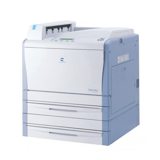
- Page 3 Introduction DRYPRO 832 is a totally dry processing laser imager. This product is easy to use and environmentally friendly while maintaining sophisticated features and high image quality. This manual provides repair precautions and a series of steps for service engineers who repair this machine (or system including this machine).
-
Page 4: How To Read This Manual
Chapter 1: Safety Precautions and Warnings This chapter provides basic precautions which should be followed when repairing or using DRYPRO 832. Thoroughly read this chapter before starting work and instruct users to familiarize with these precautions. Chapter 2: Before Starting Repair Work This chapter provides basic knowledge about the product before starting repair work on DRYPRO 832. - Page 5 This chapter describes various maintenance using the service PC. Chapter 17: Troubleshooting This chapter provides solutions for errors that may occur. Chapter 18: Technical Information This chapter describes the technical information on block diagrams, wiring diagrams, board drawings, and function timing charts for the DRYPRO 832.
-
Page 6: Alert Symbol Marks
Alert Symbol Marks Alert symbols alert the person(s) who installs this machine (or system including this machine) and other people to matters and/or operation potentially hazardous to them when installing it. Read these messages and follow instructions carefully. Be sure to read all instructions and safety standards and become thoroughly familiar with the product before installing this machine. -
Page 7: Table Of Contents
Contents Contents Introduction ..................i How to Read This Manual ..............ii Structure of This Manual..............ii Alert Symbol Marks ................iv Signal Words ..................iv Chapter 1 Safety Precautions and Warnings........1-1 Warning Labels ................1-2 1.1.1 Positions and Types of Warning Labels........ 1-2 Safety Precautions ..............1-4 1.2.1 Precautions Following Requirements of... - Page 8 Contents Chapter 5 Replacing Tray Unit Loading Parts .........5-1 Placing Loading Parts ..............5-2 Replacing Supply Elevating Motor ...........5-3 Replacing Elevating Plate HP Sensor........5-6 Replacing Tray Lock Solenoid ..........5-10 Replacing Tray Detection Sensor ..........5-15 Replacing Outlet Light Shield Unit Assembly......5-20 Chapter 6 Replacing Lispl-832 (Optional) Loading Parts....6-1 Light Shield Unit ...............6-2 6.1.1 Placing Loading Parts............
- Page 9 14.3.1 Checking Print Size ............14-17 14.3.2 Main Scan OFFSET Adjustment ........14-19 14.3.3 Sub Scan OFFSET Adjustment ........14-20 Chapter 15 DRYPRO 832 Utility Tool ..........15-1 15.1 DRYPRO 832 Utility Tool Start ..........15-2 15.2 Print Queue/Delete..............15-7 15.3 Print Condition................15-9 15.4 Test Print ................15-12...
- Page 10 16.10.1 Measuring Laser Beam Intensity ........16-51 Chapter 17 Troubleshooting ............17-1 17.1 Solutions When Trouble Occurs ..........17-2 17.1.1 The DRYPRO 832 main unit will not start......17-2 17.1.2 The DRYPRO 832 stops during startup......17-3 17.1.3 An error message is displayed ........... 17-4 17.1.4 Film Jam ................
- Page 11 Contents Chapter 18 Technical Information ...........18-1 18.1 Placing Electronic Parts ............18-2 18.1.1 Supply Unit ................. 18-2 18.1.2 Lispl-832 (Optional) ............18-3 18.1.3 Sub Scan Unit, Justification Unit ........18-4 18.1.4 Heat Process Unit............... 18-5 18.1.5 Ejection Unit ............... 18-6 18.1.6 Main Unit ................18-6 18.1.7 Exterior of Main Unit ............
- Page 13 Chapter Safety Precautions and Chapter 1 Warnings This chapter presents safety precautions you need to know prior to starting repair work on the product. Warning Labels ..........1-2 1.1.1 Positions and Types of Warning Labels ..1-2 Safety Precautions..........1-4 1.2.1 Precautions Following Requirements of Laws and Regulations........
-
Page 14: Chapter 1 Safety Precautions And Warnings
Chapter 1 Safety Precautions and Warnings Warning Labels Various warning labels are attached to DRYPRO 832 on locations shown below: When performing installation or maintenance work such as repairs, understand the meaning of warning labels and be very careful in handling locations where warning labels are affixed to. - Page 15 Chapter 1 Safety Precautions and Warnings Precautions/Warning Labels Laser Power Label...
-
Page 16: Safety Precautions
Maximum output 260mW (1) EMC Statement - DRYPRO 832 has been tested and found to comply with the limits for medical devices to the IEC 60601-1-2: 2001, Medical Device Directive 93/42/EEC or the Electromagnetic Compatibility Directive 89/ 336/EEC (use applicable directive). These limits are designed to provide reasonable protection against harmful interference in a typical medical installation. - Page 17 Guidance and manufacturer's declaration - electromagnetic emissions The DRYPRO 832 is intended for use in the electromagnetic environment specified below. The customer or the user of the DRYPRO 832 should assure that it is used in such an environment. Emissions test...
- Page 18 Guidance and manufacturer’s declaration - electromagnetic immunity The DRYPRO 832 is intended for use in the electromagnetic environment specified below. The customer or the user or the DRYPRO 832 should assure that it is used in such an environment. IEC 60601...
-
Page 19: General Precautions
RF communications equipment and the DRYPRO 832 The DRYPRO 832 is intended for use in and electromagnetic environment in which radiated RF disturbances are controlled. The customer or the user of the DRYPRO 832 can help prevent electromagnetic interference by... -
Page 20: Handling Precautions
Chapter 1 Safety Precautions and Warnings 1.2.3 Handling Precautions If unusual noise, odor, or smoke comes from this product, stop operation. If unusual noise, odor, or smoke coming from this product is detected, immediately stop operation. If you continue to operate it with abnormal condition left as it is, it could cause an electric shock, fire, or damage to the product. -
Page 21: Servicing Precautions
You could get your finger caught in sliding or rotating parts. 1.2.5 Disposing of Parts This DRYPRO 832 product (including lithium batteries), accessories, optional accessories, consumables, and media are designated as industrial waste. When disposing of these, be sure to have them disposed of by authorized industrial waste disposal firm in accordance with the applicable ordinances and regulations of the local government. -
Page 23: Chapter 2 Before Starting Repair Work
Chapter Before Starting Repair Chapter 2 Work This chapter provides basic knowledge about the product before starting repair work on DRYPRO 832. Names of Parts ..........2-2 2.1.1 Unit Exterior ..........2-2 2.1.2 Unit Interior........... 2-3 2.1.3 Supply Tray ..........2-3 2.1.4... -
Page 24: Names Of Parts
Chapter 2 Before Starting Repair Work Names of Parts Names of the parts that you need to know when installing the DRYPRO 832 unit are shown below. 2.1.1 Unit Exterior Name Name Front Cover Lower Front Cover Right Cover Supply Tray... -
Page 25: Unit Interior
Chapter 2 Before Starting Repair Work 2.1.2 Unit Interior Name Name Lever A Lever B Deodorant Filter Case Stabilizer (Internal: deodorant filter) External Guide Unit Assembly 2.1.3 Supply Tray Name Name Film Regulation Pin Cutter Guide Intermediate Plate... -
Page 26: Lispl-832 (Optional)
Rear Cover Structure The structure of DRYPRO 832 is shown below. Film is fed in the order from No. 1 to No. 5 during the printing process. However, if the Lispl-832 option is installed and film is loaded into the Lispl-832, film is fed in order from No.7 to No.2. -
Page 27: Tools, Measuring Instruments, And Jigs Necessary For Servicing
Chapter 2 Before Starting Repair Work Tools, Measuring Instruments, and Jigs Necessary for Servicing In addition to the standard tools, the following tools, measuring instruments, and jigs are necessary for servicing DRYPRO 832. Name Remarks Allen wrench Stubby screwdriver Cutter... -
Page 29: Chapter 3 Basic Operations
Chapter Basic Operations Chapter 3 This chapter describes basic operations when repairing DRYPRO 832, including the procedures for installing or removing a supply tray and exterior cover, opening or closing covers, and wearing a grounding strap. Removing/Installing Supply Tray......3-2 Opening/Closing Cover........3-4 3.2.1 Opening/Closing Front Cover....... -
Page 30: Removing/Installing Supply Tray
This section describes how to remove/install a supply tray. Use the procedure for removing a supply tray provided here with power turned OFF when installing or repairing DRYPRO 832. For information about how to remove a supply tray with Caution DRYPRO 832 turned ON, see the operation manual. - Page 31 Chapter 3 Basic Operations Installation Procedure Pull out the rails. Install the tray on the rails. Place the supply tray so that the pinhole in the rails aligns with the pin position on the back of the supply tray. Push in the supply tray until it clicks into place.
-
Page 32: Opening/Closing Cover
Chapter 3 Basic Operations Opening/Closing Cover This section describes how to open or close the front cover and right cover. 3.2.1 Opening/Closing Front Cover This section describes how to open or close the front cover. How to open the front cover Open the front cover. -
Page 33: Opening/Closing Right Cover
Chapter 3 Basic Operations 3.2.2 Opening/Closing Right Cover This section describes how to open or close the right cover. How to open the right cover Open the front cover. The front cover will open by pulling its upper part on both sides. -
Page 34: Removing/Installing Exterior Cover
Chapter 3 Basic Operations Removing/Installing Exterior Cover 3.3.1 Removing/Installing Lower Right Cover This section describes how to remove/install the lower right cover. Be sure to turn off power and remove the power cable from the electrical outlet before removing or installing the exterior cover or replacing loading parts. Caution Removal Procedure Pull the tray shutter out of the lower part of the... - Page 35 Chapter 3 Basic Operations Open the right cover by rotating the lever B in the direction of an arrow. Remove the right cover from the external guide unit assembly. Slide the right cover upward, so that the tabs (four places) inside the right cover are detached from the external guide assembly, and then remove the cover.
- Page 36 Chapter 3 Basic Operations Cover Installation Procedure Install the lower right cover. • Four screws (M4×8) Slide the lower right cover upward so that the tabs (two locations) on the lower right cover hook onto the main unit to install the cover. Open the front cover.
- Page 37 Chapter 3 Basic Operations Close the right and front covers. Fit the right cover with screws. • Two screws (M4×8) Put the supply tray back into the main unit. Remove the tray shutter and return it to its original position. Take sufficient care when handling the tray shutter, as it may be impossible to insert if it Caution...
-
Page 38: Removing/Installing Film Ejection Tray
Chapter 3 Basic Operations 3.3.2 Removing/Installing Film Ejection Tray This section describes how to remove/install the film ejection tray. Be sure to turn off power and remove the power cable from the electrical outlet before removing or installing the exterior cover or replacing loading parts. Caution Removal Procedure Remove the LAN cover. - Page 39 Chapter 3 Basic Operations Installation Procedure Install the film ejection tray. • Two screws (M4×8) Connect the LAN cable to the ethernet port. Insert the LAN cable into the connector cover slots. Install the LAN cover. First insert the tabs (two places) on the top side of the LAN cover and then insert the tabs on the bottom side (two places).
-
Page 40: Removing/Installing Upper Right Cover
Chapter 3 Basic Operations 3.3.3 Removing/Installing Upper Right Cover This section describes how to remove/install the upper right cover. Be sure to turn off power and remove the power cable from the electrical outlet before removing or installing the exterior cover or replacing loading parts. Caution Removal Procedure Pull the tray shutter out of the lower part of the... - Page 41 Chapter 3 Basic Operations Open the right cover by rotating the lever B in the direction of an arrow. Remove the right cover from the external guide unit assembly. Slide the right cover upward, so that the tabs (four places) inside the right cover are detached from the external guide assembly, and then remove the cover.
- Page 42 Chapter 3 Basic Operations Remove the LAN cable from the connector cover slots. Disconnect the LAN cable. Remove the film ejection tray. • Two screws (M4×8) Remove the connector cover. Remove the upper right cover. • Two screws (M4×8) Slide the upper right cover upward so that the tab (one location) on the upper right cover is detached from the main unit, and then remove the cover.
- Page 43 Chapter 3 Basic Operations Installation Procedure Install the upper right cover. • Two screws (M4×8) Slide the upper right cover downward so that the tab (one location) on the upper right cover hooks onto the main unit to install the cover. Install the connector cover.
- Page 44 Chapter 3 Basic Operations Insert the LAN cable into the connector cover slots. Install the LAN cover. First insert the tabs (two places) on the top side of the LAN cover and then insert the tabs on the bottom side (two places).
- Page 45 Chapter 3 Basic Operations Install the right cover. Hook the tabs (four locations) on the inside of the right cover onto the external guide assembly, and slide the right cover downward to install. Close the front and right covers. Fit the right cover with screws. •...
-
Page 46: Removing/Installing Rear Cover
Chapter 3 Basic Operations 3.3.4 Removing/Installing Rear Cover This section describes how to remove/install the rear cover. Be sure to turn off power and remove the power cable from the electrical outlet before removing or installing the exterior cover or replacing loading parts. Caution Removal Procedure Pull the tray shutter out of the lower part of the... - Page 47 Chapter 3 Basic Operations Installation Procedure Install the rear cover. • Six screws (M4×8) Put the supply tray back into the main unit. Remove the tray shutter and return it to its original position. Take sufficient care when handling the tray shutter, as it may be impossible to insert if it Caution becomes deformed due to rough handling.
-
Page 48: Removing/Installing Rear Cover (Lispl-832)
Chapter 3 Basic Operations 3.3.5 Removing/Installing Rear Cover (Lispl-832) This section describes how to remove/install Lispl-832 tray rear cover. Be sure to turn off power and remove the power cable from the electrical outlet before removing or installing the exterior cover or replacing loading parts. Caution Removal Procedure Pull the tray shutter out of the lower part of the... - Page 49 Chapter 3 Basic Operations Installation Procedure Install the rear cover. • Six screws (M4×8) Put the supply tray back into the main unit. Remove the tray shutter and return it to its original position. Take sufficient care when handling the tray shutter, as it may be impossible to insert if it Caution becomes deformed due to rough handling.
-
Page 50: Removing/Installing Left Cover
Chapter 3 Basic Operations 3.3.6 Removing/Installing Left Cover This section describes how to remove/install the left cover. Be sure to turn off power and remove the power cable from the electrical outlet before removing or installing the exterior cover or replacing loading parts. Caution Removal Procedure Pull the tray shutter out of the lower part of the... - Page 51 Chapter 3 Basic Operations Installation Procedure Install the left cover. • Four screws (M4×8) Slide the left cover downward so that the tabs (two locations) inside the left cover hook onto the main unit to install the cover. Put the supply tray back into the main unit. Remove the tray shutter and return it to its original position.
-
Page 52: Installing A Grounding Strap
Chapter 3 Basic Operations Installing a Grounding Strap To avoid damage to the system board caused by electrostatic discharge, wear a wrist grounding strap when accessing the system board for work. Caution Ground yourself by using a wrist grounding strap and put the other clip in a metal part of the main unit that makes a good ground. - Page 53 Chapter Replacing Supply Unit Chapter 4 Loading Parts This chapter describes how to replace loading parts in the supply unit when they fail and how to adjust after replacing the loading parts. Light Shield Unit..........4-2 4.1.1 Placing Loading Parts ........4-2 4.1.2 Removing/Installing Light Shield Assembly ...
-
Page 54: Chapter 4 Replacing Supply Unit Loading Parts
Chapter 4 Replacing Supply Unit Loading Parts Light Shield Unit 4.1.1 Placing Loading Parts The light shield unit in the supply unit includes the following loading parts. Name Functions and Reference Sections Barrier bag detection This photo sensor detects the presence or absence of the barrier bag. sensor For more information, see “4.1.3 Replacing Barrier Bag Detection Sensor... -
Page 55: Removing/Installing Light Shield Assembly
Chapter 4 Replacing Supply Unit Loading Parts 4.1.2 Removing/Installing Light Shield Assembly This section describes the procedure for removing or installing the light shield unit assembly when replacing loading parts in the light shield unit. Be sure to turn off power and remove the power cable from the electrical outlet before removing or installing the exterior cover or replacing load parts. - Page 56 Chapter 4 Replacing Supply Unit Loading Parts Remove the lower front cover. • Two screws (M3×8) Remove the connector (JJ48). For Lispl-832, remove the Lispl-832 side connector (JJ48). When removing the connector, do not pull by the wires, but hold the tab on the connector Caution with your fingers.
- Page 57 Chapter 4 Replacing Supply Unit Loading Parts Connect the connector (JJ48). For Lispl-832, remove the Lispl-832 side connector (JJ48). Be sure to push the connector all the way in when connecting it. Caution If the connector is not connected properly, an error will occur and, in some cases, smoke and/or an odor may be generated.
-
Page 58: Replacing Barrier Bag Detection Sensor
Chapter 4 Replacing Supply Unit Loading Parts 4.1.3 Replacing Barrier Bag Detection Sensor Replace the photo sensor that detects the presence or absence of the barrier bag. Be sure to turn off power and remove the power cable from the electrical outlet before removing or installing the exterior cover or replacing load parts. - Page 59 Chapter 4 Replacing Supply Unit Loading Parts Connect the connector (JP30) removed in step Be sure to push the connector all the way in when connecting it. If the connector is not connected properly, an error will occur and, in some cases, smoke and/or Caution an odor may be generated.
-
Page 60: Replacing Film Height Detection Sensor
Chapter 4 Replacing Supply Unit Loading Parts 4.1.4 Replacing Film Height Detection Sensor Replace the photo sensor that detects the height of film loaded in the supply tray. Be sure to turn off power and remove the power cable from the electrical outlet before removing or installing the exterior cover or replacing load parts. - Page 61 Chapter 4 Replacing Supply Unit Loading Parts Connect the connector (JP29) removed in step Be sure to push the connector all the way in when connecting it. If the connector is not connected properly, an error will occur and, in some cases, smoke and/or Caution an odor may be generated.
-
Page 62: Pickup Unit
Chapter 4 Replacing Supply Unit Loading Parts Pickup Unit 4.2.1 Placing Loading Parts The pickup unit in the supply unit includes the following loading parts. Name Functions and Reference Sections Pickup transport This motor drives the pickup roller. motor For more information, see “4.2.3 Replacing Pickup Transport Motor (Page 4-15)”. -
Page 63: Removing/Installing Pickup Unit Assembly
Chapter 4 Replacing Supply Unit Loading Parts 4.2.2 Removing/Installing Pickup Unit Assembly This section describes the procedure for removing or installing the pickup unit assembly when replacing the loading parts in the pickup unit assembly. Be sure to turn off power and remove the power cable from the electrical outlet before removing or installing the exterior cover or replacing load parts. - Page 64 Chapter 4 Replacing Supply Unit Loading Parts Remove the lower front cover. • Two screws (M3×8) Remove the connector (JJ48). For Lispl-832, remove the Lispl-832 side connector (JJ48). When removing the connector, do not pull by the wires, but hold the tab on the connector Caution with your fingers.
- Page 65 Chapter 4 Replacing Supply Unit Loading Parts Installation Procedure Install the pickup unit assembly. Insert the pickup unit assembly all the way in along the guides while being careful not to Caution cause any damage by coming into contact with the parts inside the main unit. If the pickup unit assembly is not installed properly, it may be impossible to install the light shield unit assembly.
- Page 66 Chapter 4 Replacing Supply Unit Loading Parts Put the supply tray back into the main unit. Remove the tray shutter and return it to the previous position. Take sufficient care when handling the tray shutter, as it may be impossible to insert if it Caution becomes deformed due to rough handling.
-
Page 67: Replacing Pickup Transport Motor
Chapter 4 Replacing Supply Unit Loading Parts 4.2.3 Replacing Pickup Transport Motor Replace the motor that drives the pickup roller. Be sure to turn off power and remove the power cable from the electrical outlet before removing or installing the exterior cover or replacing load parts. Caution Work outline The number of personnel and the estimated work hours required to replace load parts is as follows:... - Page 68 Chapter 4 Replacing Supply Unit Loading Parts Remove the bracket. • Two screws (M3×6) Remove the connector (JP53). When removing the connector, do not pull by the wires, but hold the tab on the connector Caution with your fingers. Pulling by the wires too tightly can cause a break.
- Page 69 Chapter 4 Replacing Supply Unit Loading Parts Install the bracket removed in step • Two screws (M3×6) When a gear or collar comes off in removing the bracket, install by referring to the figure below. When attaching a gear or collar, attention should be paid to the gear or collar orientation. Caution After installing the gear back, move the neighboring gears with your hand to make sure that it moves in response to the other gears.
-
Page 70: Replacing Pickup Hp Motor
Chapter 4 Replacing Supply Unit Loading Parts 4.2.4 Replacing Pickup HP Motor Replace the drive motor that saves the pickup roller. Be sure to turn off power and remove the power cable from the electrical outlet before removing or installing the exterior cover or replacing load parts. Caution Work outline The number of personnel and the estimated work hours required to replace load parts is as follows:... - Page 71 Chapter 4 Replacing Supply Unit Loading Parts Remove the gear. Remove the pickup HP motor. • Two screws (M3×4) Install a new pickup HP motor. • Two screws (M3×4) Install the gear removed in step Push in the gear so that the notch on the gear aligns with the notch on the shaft.
-
Page 72: Replacing Pickup Hp Sensor
Chapter 4 Replacing Supply Unit Loading Parts 4.2.5 Replacing Pickup HP Sensor Replace the photo sensor that detects when the pickup roller is in its Home position. Be sure to turn off power and remove the power cable from the electrical outlet before removing or installing the exterior cover or replacing load parts. - Page 73 Chapter 4 Replacing Supply Unit Loading Parts Push the tab on the back of the sensor inward and remove the photo sensor. Insert a new photo sensor in the mounting hole. Install the bracket removed in step • One screw (M3×6) Fix so that the positioning hole in the bracket aligns with the emboss on the mating part.
- Page 75 Chapter Replacing Tray Unit Chapter 5 Loading Parts This chapter describes how to replace loading parts in the tray unit when they fail and how to adjust after replacing the loading parts. Placing Loading Parts ........5-2 Replacing Supply Elevating Motor .....5-3 Replacing Elevating Plate HP Sensor....5-6 Replacing Tray Lock Solenoid ......5-10 Replacing Tray Detection Sensor ....5-15...
-
Page 76: Chapter 5 Replacing Tray Unit Loading Parts
For more information, see “5.3 Replacing Elevating Plate HP Sensor (Page 5-6)”. Tray lock solenoid This solenoid valve locks or unlocks the supply tray in DRYPRO 832. For more information, see “5.4 Replacing Tray Lock Solenoid (Page 5-10)”. Tray detection sensor This photo sensor detects presence or absence of the supply tray. -
Page 77: Replacing Supply Elevating Motor
Chapter 5 Replacing Tray Unit Loading Parts Replacing Supply Elevating Motor Replace the motor that drives the elevating plate that moves up when transporting film. Be sure to turn off power and remove the power cable from the electrical outlet before removing or installing the exterior cover or replacing loading parts. - Page 78 Chapter 5 Replacing Tray Unit Loading Parts Remove the rear cover. • Six screws (M4×8) Remove the upper two screws and the one screw in the center from the rear cover and loosen the Note bottom three. Proceed to step Remove the rear cover of Lispl-832.
- Page 79 Chapter 5 Replacing Tray Unit Loading Parts Install the bracket removed in step • One screw (M3×6) Hook the notch of the bracket onto the notch of the main unit to attach. Connect the connector removed in step • If the tray unit supply elevating motor has been replaced, connect the connector (JP56). •...
-
Page 80: Replacing Elevating Plate Hp Sensor
Chapter 5 Replacing Tray Unit Loading Parts Replacing Elevating Plate HP Sensor Replace the photo sensor detects the position (Home Position) where the elevating plate is lowered. Be sure to turn off power and remove the power cable from the electrical outlet before removing or installing the exterior cover or replacing loading parts. - Page 81 Chapter 5 Replacing Tray Unit Loading Parts Remove the rear cover. • Six screws (M4×8) Remove the upper two screws and the one screw in the center from the rear cover and loosen the Note bottom three. Proceed to step Remove the rear cover of Lispl-832.
- Page 82 Chapter 5 Replacing Tray Unit Loading Parts Remove the bracket. • One screw (M3×6) The bracket is hooked on the notch in the main unit, but can be unhooked by sliding slightly to the right and pulling back. Push the tab on the back of the sensor inward and remove the photo sensor.
- Page 83 Chapter 5 Replacing Tray Unit Loading Parts Connect the connector removed in step • If the tray unit elevating plate HP sensor has been replaced, connect the connector (JP56). • If the Lispl-832 elevating plate HP sensor has been replaced, connect the connector (JP64). Be sure to push the connector all the way in when connecting it.
-
Page 84: Replacing Tray Lock Solenoid
Chapter 5 Replacing Tray Unit Loading Parts Replacing Tray Lock Solenoid Replace the solenoid valve that locks or unlocks the supply tray. Be sure to turn off power and remove the power cable from the electrical outlet before removing or installing the exterior cover or replacing loading parts. Caution Work outline The number of personnel and the estimated work hours required to replace loading parts is as follows:... - Page 85 Chapter 5 Replacing Tray Unit Loading Parts Remove the rear cover. • Six screws (M4×8) Remove the upper two screws and the one screw in the center from the rear cover and loosen the Note bottom three. Proceed to step Remove the rear cover of Lispl-832.
- Page 86 Chapter 5 Replacing Tray Unit Loading Parts Remove the connector cover. • One screw (M3×6) If the Lispl-832 is connected, remove the connector cover after removing the connector Note (JP16, JP 26). Remove the cover. ・ Two screws (M3×6) Proceed to step Remove the Lispl-832 connector cover.
- Page 87 Chapter 5 Replacing Tray Unit Loading Parts Remove the tray lock solenoid unit assembly. • Three screws (M3×6) The bracket is hooked on the notch in the main unit, but can be unhooked by sliding slightly to the right and pulling back. Remove the E ring with a precision screwdriver, and extract the parallel pin.
- Page 88 Chapter 5 Replacing Tray Unit Loading Parts Install the connector cover removed in step 7 step • One screw (M3×6) If connecting the Lispl-832, connect connectors (JP16, JP 26). Note • If the tray unit tray lock solenoid has been replaced, proceed to step •...
-
Page 89: Replacing Tray Detection Sensor
Chapter 5 Replacing Tray Unit Loading Parts Replacing Tray Detection Sensor Replace the photo sensor that detects the presence or absence of the supply tray. Be sure to turn off power and remove the power cable from the electrical outlet before removing or installing the exterior cover or replacing loading parts. - Page 90 Chapter 5 Replacing Tray Unit Loading Parts Remove the rear cover. • Six screws (M4×8) Remove the upper two screws and the one screw in the center from the rear cover and loosen the Note bottom three. Proceed to step Remove the rear cover of Lispl-832.
- Page 91 Chapter 5 Replacing Tray Unit Loading Parts Remove the connector cover. • One screw (M3×6) If the Lispl-832 is connected, remove the connector cover after removing the connector Note (JP16, JP 26). Remove the cover. ・ Four screws (M3×6) Proceed to step Remove the Lispl-832 connector cover.
- Page 92 Chapter 5 Replacing Tray Unit Loading Parts Remove the tray lock solenoid unit assembly. • Three screws (M3×6) The bracket is hooked on the notch in the main unit, but can be unhooked by sliding slightly to the right and pulling back. Push the tab on the back of the sensor inward and remove the photo sensor.
- Page 93 Chapter 5 Replacing Tray Unit Loading Parts Install the cover removed in step • Two screws (M3×6) Install the bracket removed in step • One screw (M3×6) Hook the notch of the bracket onto the notch of the main unit to attach.
-
Page 94: Replacing Outlet Light Shield Unit Assembly
Chapter 5 Replacing Tray Unit Loading Parts Replacing Outlet Light Shield Unit Assembly Replace the outlet light shield unit assembly that is used for shading the film inside the supply tray when the right cover is opened. • Be sure to turn OFF power and remove the power cable from the electrical outlet before removing or installing the exterior cover or replacing loading parts. - Page 95 Chapter 5 Replacing Tray Unit Loading Parts Open the front cover. The front cover will open by pulling the upper part of both sides. Do not push down or place objects on the opened front cover. Failure to observe this Caution caution can cause the front cover to break.
- Page 96 Chapter 5 Replacing Tray Unit Loading Parts Remove the outlet light shield unit assembly. ・ Four screws Install the new outlet light shield unit assembly. ・ Four screws Continue to step Remove the outlet light shield unit assembly. ・ Four screws Install the new outlet light shield unit assembly.
- Page 97 Chapter Replacing Lispl-832 Chapter 6 (Optional) Loading Parts This chapter describes how to replace loading parts in Lispl-832 (optional) when they fail and how to adjust after replacing the loading parts. Light Shield Unit..........6-2 6.1.1 Placing Loading Parts ........6-2 Pickup Unit............6-3 6.2.1 Placing Loading Parts ........
-
Page 98: Chapter 6 Replacing Lispl-832 (Optional) Loading Parts
Chapter 6 Replacing Lispl-832 (Optional) Loading Parts Light Shield Unit 6.1.1 Placing Loading Parts The Lispl-832 light shield unit includes the following loading parts. Name Functions and Reference Sections Barrier bag detection This photo sensor detects the presence or absence of the barrier bag. sensor Use the same replacement procedure as that for replacing the supply unit. -
Page 99: Pickup Unit
Chapter 6 Replacing Lispl-832 (Optional) Loading Parts Pickup Unit 6.2.1 Placing Loading Parts The Lispl-832 pickup unit includes the following loading parts. Name Functions and Reference Sections Pickup transport This motor drives the pickup roller. motor Use the same replacement procedure as that for replacing the supply unit. For more information, see “4.2.3 Replacing Pickup Transport Motor (Page 4-15)”. -
Page 100: Supply Unit
“5.3 Replacing Elevating Plate HP Sensor (Page 5-6)”. Tray lock solenoid This solenoid valve locks or unlocks the supply tray in DRYPRO 832. Use the same replacement procedure as that for replacing the tray unit. For more information, see “5.4 Replacing Tray Lock Solenoid (Page 5-10)”. -
Page 101: Replacing Elevating Transport Motor
Chapter 6 Replacing Lispl-832 (Optional) Loading Parts 6.3.2 Replacing Elevating Transport Motor Replace the motor that transports film from the Lispl-832 tray. Be sure to turn off power and remove the power cable from the electrical outlet before removing or installing the exterior cover or replacing loading parts. Caution Work outline The number of personnel and the estimated work hours required to replace loading parts is as follows:... - Page 102 Chapter 6 Replacing Lispl-832 (Optional) Loading Parts Remove the connector (JP64). When removing the connector, do not pull by the wires, but hold the tab on the connector Caution with your fingers. Pulling by the wires too tightly can cause a break.
- Page 103 Chapter 6 Replacing Lispl-832 (Optional) Loading Parts Remove the elevating transport motor. • Four screws (M3×6) Install a new elevating transport motor. • Four screws (M3×6) Install the gears removed in step • Two gears Install the E ring removed in step When attaching gears, attention should be paid to the gear orientation.
-
Page 104: Elevating Transport Unit
Chapter 6 Replacing Lispl-832 (Optional) Loading Parts Elevating Transport Unit The elevating transport unit in the Lispl-832 (optional) includes the following loading parts: Name Functions and Reference Sections Elevating transport nip This motor opens or closes the elevating transport nip. opening/closing motor For more information, see “6.4.2 Replacing Elevating Transport Nip... -
Page 105: Removing/Installing Elevating Transport Unit
Chapter 6 Replacing Lispl-832 (Optional) Loading Parts 6.4.1 Removing/Installing Elevating Transport Unit This section describes the procedure for removing or installing the elevating transport unit when replacing loading parts in the Lispl-832 (optional). Be sure to turn off power and remove the power cable from the electrical outlet before removing or installing the exterior cover or replacing loading parts. - Page 106 Chapter 6 Replacing Lispl-832 (Optional) Loading Parts Remove the right cover and lower right with reference to “3.3.1 Removing/Installing Lower Right Cover (Page 3-6)”. Remove the screws from the right cover. • Four screws (M4×8) Insert the long screwdriver through the access hole and unlock the right cover.
- Page 107 Chapter 6 Replacing Lispl-832 (Optional) Loading Parts This is the end of the process of removing the elevating transport unit. • When replacing the elevating transport nip opening/closing motor, go to “6.4.2 Replacing Elevating Transport Nip Opening/Closing Motor (Page 6-13)”. •...
- Page 108 Chapter 6 Replacing Lispl-832 (Optional) Loading Parts Install the lower right cover and right cover with reference to “3.3.1 Removing/Installing Lower Right Cover (Page 3-6)”. Put the supply tray back into the main unit. Remove the tray shutter and return it to the previous position.
-
Page 109: Replacing Elevating Transport Nip Opening/Closing Motor
Chapter 6 Replacing Lispl-832 (Optional) Loading Parts 6.4.2 Replacing Elevating Transport Nip Opening/Closing Motor Replace the motor opens or closes the elevating transport nip. Be sure to turn off power and remove the power cable from the electrical outlet before removing or installing the exterior cover or replacing loading parts. - Page 110 Chapter 6 Replacing Lispl-832 (Optional) Loading Parts Remove the elevating transport nip opening/ closing motor. • Two screws (M3×4) Install a new elevating transport nip opening/ closing motor. Install the gears removed in step • Two gears Install the E ring removed in step When attaching gears, attention should be paid to the gear orientation.
-
Page 111: Replacing Elevating Transport Nip Opening/Closing Hp Sensor
Chapter 6 Replacing Lispl-832 (Optional) Loading Parts 6.4.3 Replacing Elevating Transport Nip Opening/Closing HP Sensor Replace the photo sensor that detects opening/closing HP of the elevating transport nip. Be sure to turn off power and remove the power cable from the electrical outlet before removing or installing the exterior cover or replacing loading parts. - Page 112 Chapter 6 Replacing Lispl-832 (Optional) Loading Parts Remove the bracket. • One screw (M3×6) The bracket shaped like a hook is inserted into the main body. While sliding the bracket slightly, pull it out. Push the tab on the back of the sensor inward and remove the photo sensor.
- Page 113 Chapter 6 Replacing Lispl-832 (Optional) Loading Parts Put the wire removed in step 3 back into the slot on the bracket. Install the elevating transport unit , right cover, and rear cover with reference to “ Installation Procedure (Page 6-11)” “6.4.1 Removing/Installing Elevating Transport Unit”.
-
Page 114: Replacing Supply Outlet Sensor
Chapter 6 Replacing Lispl-832 (Optional) Loading Parts 6.4.4 Replacing Supply Outlet Sensor This photo sensor detects film transfer at the outlet of Lispl-832. Be sure to turn off power and remove the power cable from the electrical outlet before removing or installing the exterior cover or replacing loading parts. - Page 115 Chapter 6 Replacing Lispl-832 (Optional) Loading Parts Remove the E ring with a precision screwdriver. ・ One E ring When removing the E ring, be sure not to exert too much force. Doing so may cause Caution you to stab your finger with the precision screwdriver, or may cause the E ring to spring out and become lost.
- Page 116 Chapter 6 Replacing Lispl-832 (Optional) Loading Parts Remove the connector (JP43). When removing the connector, do not pull by the wires, but hold the tab on the connector Caution with your fingers. Pulling by the wires too tightly can cause a break.
- Page 117 Chapter 6 Replacing Lispl-832 (Optional) Loading Parts Install the E ring removed in step ・ One E ring Install the actuator assembly removed in step Install the face panel removed in step ・ Three screws (M3×6) Slide the face panel so as to unhook its tabs (4 places) from the elevating transport unit and remove it from the unit. Install the elevating transport unit , right cover, and rear cover with reference to “...
- Page 119 Chapter Replacing Sub Scan Unit Chapter 7 Loading Parts This chapter describes how to replace loading parts in the sub scan unit when they fail and how to adjust after replacing the loading parts. Placing Loading Parts ........7-2 Removing/Installing Sub Scan Unit (Including the Exposure Unit and Position Regulation Unit) ..7-4 Replacing Sub Scan Unit (Including the Position Regulation Unit) .........7-10...
-
Page 120: Chapter 7 Replacing Sub Scan Unit Loading Parts
Chapter 7 Replacing Sub Scan Unit Loading Parts Placing Loading Parts Sub Scan Unit The sub scan unit includes the following loading parts. Name Functions and Reference Sections Right cover detection This photo sensor detects the opening/closing of the right cover. sensor For more information, see “7.4 Replacing Right Cover Detection Sensor... - Page 121 Chapter 7 Replacing Sub Scan Unit Loading Parts Position Regulation Unit The position regulation unit includes the following loading parts. Name Functions and Reference Sections Reference guide This guide regulates the film position during transport to align the image position. For more information, see “7.14 Replacing Reference Guide (Page 7-44)”.
-
Page 122: Removing/Installing Sub Scan Unit (Including The Exposure Unit And Position Regulation Unit)
Chapter 7 Replacing Sub Scan Unit Loading Parts Removing/Installing Sub Scan Unit (Including the Exposure Unit and Position Regulation Unit) This section describes the procedure for removing or installing the sub scan unit (including the exposure unit and position regulation unit) when replacing loading parts in the sub scan unit. Be sure to turn off power and remove the power cable from the electrical outlet before removing or installing the exterior cover or replacing loading parts. - Page 123 Chapter 7 Replacing Sub Scan Unit Loading Parts Open the front cover. The front cover will open by pulling its upper part on both sides. Do not push down or place objects on the opened front cover. Failure to observe this Caution caution can cause the breakdown.
- Page 124 Chapter 7 Replacing Sub Scan Unit Loading Parts Remove the fixing screws of sub scan unit. • Four screws (M4×8) Remove the connectors (JJ15) and (JJ18). When removing the connector, do not pull by the wires, but hold the tab on the connector Caution with your fingers.
- Page 125 Chapter 7 Replacing Sub Scan Unit Loading Parts Pull out the sub scan unit toward you until it gets caught and slightly lift it to remove. • When pulling out the sub scan unit, be careful not to get it hung up on a wire. Caution •...
- Page 126 Chapter 7 Replacing Sub Scan Unit Loading Parts Install the ground wire. • One screw (M4×8)×2 Connect the connectors (CCN6) and (JJ25). Be sure to push the connector all the way in when connecting it. Caution If the connector is not connected properly, an error will occur and, in some cases, smoke and/or an odor may be generated.
- Page 127 Chapter 7 Replacing Sub Scan Unit Loading Parts Close the external guide unit assembly. Install the upper right cover, connector cover, film ejection tray, LAN cover, lower right cover, and right cover with reference to “ Installation Procedure (Page 3-15)” “3.3.3 Removing/ Installing Upper Right Cover”.
-
Page 128: Replacing Sub Scan Unit (Including The Position Regulation Unit)
Chapter 7 Replacing Sub Scan Unit Loading Parts Replacing Sub Scan Unit (Including the Position Regulation Unit) This section describes the procedure for replacing the sub scan unit (including the position regulation unit). Be sure to turn OFF the power and remove the power cable from the electrical outlet before removing or installing the exterior cover or replacing loading parts. - Page 129 Chapter 7 Replacing Sub Scan Unit Loading Parts Remove the connector (JP10). When removing the connector, do not pull by the wires, but hold the tab on the connector Caution with your fingers. Pulling by the wires too tightly can cause it to break.
-
Page 130: Replacing Right Cover Detection Sensor
Chapter 7 Replacing Sub Scan Unit Loading Parts Replacing Right Cover Detection Sensor Replace the photo sensor that detects the opening or closing of the right cover. Be sure to turn off power and remove the power cable from the electrical outlet before removing or installing the exterior cover or replacing loading parts. - Page 131 Chapter 7 Replacing Sub Scan Unit Loading Parts Open the external guide unit assembly by rotating the lever B in the direction of an arrow. Remove the cover. • Two screws (M3×6) Remove the bracket. • One screw (M3×6) Push the tab on the back of the sensor inward and remove the photo sensor.
- Page 132 Chapter 7 Replacing Sub Scan Unit Loading Parts Install the cover removed in step • Two screws (M3×6) Close the external guide unit assembly opened in step Install the upper right cover, connector cover, film ejection tray, LAN cover, lower right cover, and right cover with reference to “...
-
Page 133: Replacing Position Regulation Inlet Sensor
Chapter 7 Replacing Sub Scan Unit Loading Parts Replacing Position Regulation Inlet Sensor Replace the photo sensor that detects film transportation at the inlet of the justification unit. Be sure to turn off power and remove the power cable from the electrical outlet before removing or installing the exterior cover or replacing loading parts. - Page 134 Chapter 7 Replacing Sub Scan Unit Loading Parts Remove the connector (JP10). When removing the connector, do not pull by the wires, but hold the tab on the connector Caution with your fingers. Pulling by the wires too tightly can cause it to break.
- Page 135 Chapter 7 Replacing Sub Scan Unit Loading Parts Remove the bracket. • One screw (M3×6) Remove the light shield bracket. • One screw (M3×6) Push the tab on the back of the sensor inward and remove the photo sensor. Insert a new photo sensor in the mounting hole. Install the bracket removed in step •...
- Page 136 Chapter 7 Replacing Sub Scan Unit Loading Parts Connect the connector (JJ51) removed in step Be sure to push the connector all the way in when connecting it. If the connector is not connected properly, an error will occur and, in some cases, smoke and/or Caution an odor may be generated.
-
Page 137: Replacing Position Regulation Transport Motor
Chapter 7 Replacing Sub Scan Unit Loading Parts Replacing Position Regulation Transport Motor Replace the drive motor used to transport film in the justification unit. Be sure to turn off power and remove the power cable from the electrical outlet before removing or installing the exterior cover or replacing loading parts. - Page 138 Chapter 7 Replacing Sub Scan Unit Loading Parts Remove the connector (JP10). When removing the connector, do not pull by the wires, but hold the tab on the connector Caution with your fingers. Pulling by the wires too tightly can cause a break.
- Page 139 Chapter 7 Replacing Sub Scan Unit Loading Parts Remove the bracket. • Four screws (M3×6) Removing the gear fixing parallel pin. • One parallel pin Remove the E ring with a precision screwdriver. ・ E rings in two locations When removing the E ring, be sure not to exert too much force.
- Page 140 Chapter 7 Replacing Sub Scan Unit Loading Parts Connect the connector (JP10) removed in step Be sure to push the connector all the way in when connecting it. If the connector is not connected properly, an error will occur and, in some cases, smoke and/or Caution an odor may be generated.
-
Page 141: Replacing Moderation Belt
Chapter 7 Replacing Sub Scan Unit Loading Parts Replacing Moderation belt Replace the Moderation belt that transfers drive of the transport motor to the inlet roller. Be sure to turn off power and remove the power cable from the electrical outlet before removing or installing the exterior cover or replacing loading parts. - Page 142 Chapter 7 Replacing Sub Scan Unit Loading Parts Remove the Moderation belt by loosening the belt tension. If you touch the belt with bare hands, it can cause dust and dirt to adhere to the belt, Caution resulting in pitch irregularity and image inconsistencies.
-
Page 143: Replacing Transfer Belt
Chapter 7 Replacing Sub Scan Unit Loading Parts Replacing Transfer belt Replace the Transfer belt that transfers drive of the inlet roller to the outlet roller. Be sure to turn off power and remove the power cable from the electrical outlet before removing or installing the exterior cover or replacing loading parts. - Page 144 Chapter 7 Replacing Sub Scan Unit Loading Parts Remove the Transfer belt by loosening the belt tension. If you touch the belt with bare hands, it can cause dust and dirt to adhere to the belt, Caution resulting in pitch irregularity and image inconsistencies.
-
Page 145: Replacing Sub Scan Transport Motor
Chapter 7 Replacing Sub Scan Unit Loading Parts Replacing Sub Scan Transport Motor Replace the drive motor used to transport film in the sub scan unit. Be sure to turn off power and remove the power cable from the electrical outlet before removing or installing the exterior cover or replacing loading parts. - Page 146 Chapter 7 Replacing Sub Scan Unit Loading Parts Remove the connector (JP10). When removing the connector, do not pull by the wires, but hold the tab on the connector with your Caution fingers. Pulling by the wires too tightly can cause it to break.
- Page 147 Chapter 7 Replacing Sub Scan Unit Loading Parts Remove the connector (JP59). When removing the connector, do not pull by the wires but hold the tab on the connector with your Caution fingers. Pulling by the wires too tightly can cause a break. Remove the Sub Scan transport motor.
-
Page 148: Replacing Sub Scan Nip Motor
Chapter 7 Replacing Sub Scan Unit Loading Parts 7.10 Replacing Sub Scan Nip Motor Replace the motor that drives the nip in the sub scan unit. Be sure to turn off power and remove the power cable from the electrical outlet before removing or installing the exterior cover or replacing loading parts. - Page 149 Chapter 7 Replacing Sub Scan Unit Loading Parts Remove the connector (JP10). When removing the connector, do not pull by the wires, but hold the tab on the connector Caution with your fingers. Pulling by the wires too tightly can cause it to break.
- Page 150 Chapter 7 Replacing Sub Scan Unit Loading Parts Remove the bracket. • Two screws (M3×6) Remove the set screw. • One set screw (M3×6) Remove the gears. Remove the Sub Scan nip motor. • Two screws (M3×4) Install a new Sub Scan nip motor. •...
- Page 151 Chapter 7 Replacing Sub Scan Unit Loading Parts Refer to step 6 “8.2 Replacing Exposure Unit (Page 8-3)” and install the exposure unit. Install the sub scan unit with reference to “ Installation Procedure (Page 7-7)” “7.2 Removing/Installing Sub Scan Unit (Including the Exposure Unit and Position Regulation Unit)”.
-
Page 152: Replacing Sub Scan Inlet Sensor
Chapter 7 Replacing Sub Scan Unit Loading Parts 7.11 Replacing Sub Scan Inlet Sensor Replace the photo sensor that detects film transportation at the inlet of the sub scan unit. Be sure to turn off power and remove the power cable from the electrical outlet before removing or installing the exterior cover or replacing loading parts. - Page 153 Chapter 7 Replacing Sub Scan Unit Loading Parts Remove the connector (JP10). When removing the connector, do not pull by the wires, but hold the tab on the connector Caution with your fingers. Pulling by the wires too tightly can cause it to break.
- Page 154 Chapter 7 Replacing Sub Scan Unit Loading Parts Remove the sensor cover. • One screw (M3×6) Push the tab on the back of the sensor inward and remove the photo sensor. Insert a new photo sensor in the mounting hole. Install the sensor cover removed in step •...
- Page 155 Chapter 7 Replacing Sub Scan Unit Loading Parts Refer to step 6 “8.2 Replacing Exposure Unit (Page 8-3)” and install the exposure unit. Install the sub scan unit with reference to “ Installation Procedure (Page 7-7)” “7.2 Removing/Installing Sub Scan Unit (Including the Exposure Unit and Position Regulation Unit)”.
-
Page 156: Replacing Sub Scan Nip Hp Sensor
Chapter 7 Replacing Sub Scan Unit Loading Parts 7.12 Replacing Sub Scan Nip HP Sensor Replace the photo sensor that detects the home position of the nip in the sub scan unit. Be sure to turn off power and remove the power cable from the electrical outlet before removing or installing the exterior cover or replacing loading parts. - Page 157 Chapter 7 Replacing Sub Scan Unit Loading Parts Place the sub scan unit upside down and remove the connectors (JP58) and (JP35). When removing the connector, do not pull by the wires, but hold the tab on the connector Caution with your fingers.
-
Page 158: Replacing V-Sync Sensor
Chapter 7 Replacing Sub Scan Unit Loading Parts 7.13 Replacing V-sync Sensor Replace the photo sensor that detects film transportation in the sub scan unit. Be sure to turn off power and remove the power cable from the electrical outlet before removing or installing the exterior cover or replacing loading parts. - Page 159 Chapter 7 Replacing Sub Scan Unit Loading Parts Remove the connector (JP10). When removing the connector, do not pull by the wires, but hold the tab on the connector Caution with your fingers. Pulling by the wires too tightly can cause it to break.
- Page 160 Chapter 7 Replacing Sub Scan Unit Loading Parts Remove the cover. • One screw (M3×6) Push the tab on the back of the sensor inward and remove the photo sensor. Insert a new photo sensor in the mounting hole. Install the cover removed in step •...
- Page 161 Chapter 7 Replacing Sub Scan Unit Loading Parts Refer to step 6 “8.2 Replacing Exposure Unit (Page 8-3)” and install the exposure unit. Install the sub scan unit with reference to “ Installation Procedure (Page 7-7)” “7.2 Removing/Installing Sub Scan Unit (Including the Exposure Unit and Position Regulation Unit)”.
-
Page 162: Replacing Reference Guide
Chapter 7 Replacing Sub Scan Unit Loading Parts 7.14 Replacing Reference Guide The procedure for replacing the reference guide regulates the film position during transport to align the image position. Be sure to turn OFF the power and remove the power cable from the electrical outlet before removing or installing the exterior cover or replacing loading parts. - Page 163 Chapter 7 Replacing Sub Scan Unit Loading Parts Open the front cover. The front cover will open by pulling the upper part of both sides. Do not push down or place objects on the opened front cover. Caution Failure to observe this caution can cause the front cover to break.
- Page 164 Chapter 7 Replacing Sub Scan Unit Loading Parts Close the external guide unit assembly. Install the upper right cover, connector cover, film ejection tray, LAN cover, lower right cover, and right cover with reference to “ Installation Procedure (Page 3-15)” “3.3.3 Removing/ Installing Upper Right Cover”.
-
Page 165: Chapter 8 Replacing Exposure Unit
Chapter Replacing Exposure Unit Chapter 8 This chapter describes how to replace the main scan unit. Placing Exposure Unit........8-2 Replacing Exposure Unit ........8-3... -
Page 166: Placing Exposure Unit
Chapter 8 Replacing Exposure Unit Placing Exposure Unit Name Functions and Reference Sections Exposure Unit This is an optical exposure. For more information, see “8.2 Replacing Exposure Unit (Page 8-3)”. -
Page 167: Replacing Exposure Unit
Chapter 8 Replacing Exposure Unit Replacing Exposure Unit Replace the main scan unit. Be sure to turn off power and remove the power cable from the electrical outlet before removing or installing the exterior cover or replacing loading parts. Caution Work outline The number of personnel and the estimated work hours required to replace loading parts is as follows: Number of Personnel... - Page 168 Chapter 8 Replacing Exposure Unit Remove the exposure unit. • Four screws (M4×12) The exposure unit includes optical parts. Be careful not to subject to a strong impact. Caution Remove the duct. • Four screws (M3×6) Install the duct removed in step 4 on the exposure unit.
- Page 169 Chapter 8 Replacing Exposure Unit Work after replacing the exposure unit After replacing the exposure unit, perform the following work. Exposure light parameter settings Set the values of the label attached to the exposure unit using the “Product Setup” screen. Ex1) exposure unit label Ex2) exposure unit label Ex) “PRODACT SETUP”...
- Page 170 Chapter 8 Replacing Exposure Unit Check and fine tune the printing size. For more information, see “14.3 Checking and Fine Tuning the Print Size (Page 14-17)”. This is the end of the process of replacing the exposure unit.
- Page 171 Chapter Replacing Loading Parts Chapter 9 in Heat Process Unit This chapter describes how to replace loading parts in the heat process unit when they fail and how to adjust after replacing the loading parts. Heat Process Unit Side........9-2 9.1.1 Removing/Installing Heat Process Unit..
-
Page 172: Chapter 9 Replacing Loading Parts In Heat Process Unit
Chapter 9 Replacing Loading Parts in Heat Process Unit Heat Process Unit Side The heat process side of the heat process unit includes the following loading parts. Name Functions and Reference Sections Heater The heater increases or decreases the temperature of the heat process unit. For more information, see “9.1.2 Replacing Heater (Page 9-7)”. -
Page 173: Removing/Installing Heat Process Unit
Chapter 9 Replacing Loading Parts in Heat Process Unit 9.1.1 Removing/Installing Heat Process Unit This section describes the procedure for removing or installing the heat process unit when replacing loading parts in the heat process unit. • Be sure to turn off power and remove the power cable from the electrical outlet before removing or installing the exterior cover or replacing loading parts. - Page 174 Chapter 9 Replacing Loading Parts in Heat Process Unit Remove the left cover. • Four screws (M4×8) Slide the left cover upward so that the tabs (two locations) on the inside of the left cover detach from the main unit, and remove the cover.
- Page 175 Chapter 9 Replacing Loading Parts in Heat Process Unit Pull out the heat process unit toward you until it gets caught and slightly lift it to remove. • Two screws (M3×6) • One screw (M4×15) Since the upper left screw (in the left figure) is protected from falling, it cannot be completely removed.
- Page 176 Chapter 9 Replacing Loading Parts in Heat Process Unit Connect the relay connectors (JJ60, JJ73, JJ74, JJ75, JJ76, and JJ77). Be sure to push the connector all the way in when connecting it. Caution If the connector is not connected properly, an error will occur and, in some cases, smoke and/or an odor may be generated.
-
Page 177: Replacing Heater
Chapter 9 Replacing Loading Parts in Heat Process Unit 9.1.2 Replacing Heater The heater used for increasing or decreasing the temperature of the heat process unit cannot be replaced singularly. Replace the complete set of the heat process unit. • Be sure to turn off power and remove the power cable from the electrical outlet before removing or installing the exterior cover or replacing loading parts. -
Page 178: Replacing Heat Process Temperature Sensor
Chapter 9 Replacing Loading Parts in Heat Process Unit 9.1.3 Replacing Heat Process Temperature Sensor The temperature sensor that monitors the temperature of the heater cannot be replaced singularly. Replace a complete set of the heat process unit. • Be sure to turn off power and remove the power cable from the electrical outlet before removing or installing the exterior cover or replacing loading parts. -
Page 179: Replacing Supply Cooling Fan
Chapter 9 Replacing Loading Parts in Heat Process Unit 9.1.4 Replacing Supply Cooling Fan Replace the fan unit that cools the supply unit. Be sure to turn off power and remove the power cable from the electrical outlet before removing or installing the exterior cover or replacing loading parts. - Page 180 Chapter 9 Replacing Loading Parts in Heat Process Unit Remove the supply cooling fan. • Two screws (M3×30) Remove the connector (JP66). When removing the connector, do not pull by the wires, but hold the tab on the connector Caution with your fingers.
-
Page 181: Main Unit Side
Chapter 9 Replacing Loading Parts in Heat Process Unit Main Unit Side The main unit side of the heat process unit includes the following loading parts. Name Functions and Reference Sections Heat process motor This motor drives the opposed roller. For more information, see “9.2.1 Replacing Heat Process Motor (Page 9- 12)”. -
Page 182: Replacing Heat Process Motor
Chapter 9 Replacing Loading Parts in Heat Process Unit 9.2.1 Replacing Heat Process Motor Replace the motor that drives the opposed roller. Be sure to turn off power and remove the power cable from the electrical outlet before removing or installing the exterior cover or replacing loading parts. Caution Work outline The number of personnel and the estimated work hours required to replace loading parts is as follows:... - Page 183 Chapter 9 Replacing Loading Parts in Heat Process Unit Remove the entire unit of the heat process motor. • Four screws (M4×8) Remove the circuit board supports in two positions and take off the entire unit of the heat process motor. Remove the connector (JP46).
-
Page 184: Replacing Heat Process Cooling Fans 1 And 2
Chapter 9 Replacing Loading Parts in Heat Process Unit 9.2.2 Replacing Heat Process Cooling Fans 1 and 2 Replace the fan unit that cools the heat process unit. Be sure to turn off power and remove the power cable from the electrical outlet before removing or installing the exterior cover or replacing loading parts. - Page 185 Chapter 9 Replacing Loading Parts in Heat Process Unit Remove the connector on the side to be replaced. • Heat process cooling fan 1: connector (JP19) • Heat process cooling fan 2: connector (JP20) When removing the connector, do not pull by the wires, but hold the tab on the connector Caution with your fingers.
-
Page 186: Replacing Deodorant Filter Detection Sensor
Chapter 9 Replacing Loading Parts in Heat Process Unit 9.2.3 Replacing Deodorant Filter Detection Sensor Replace the photo sensor that detects the presence or absence of the deodorant filter. • Be sure to turn off power and remove the power cable from the electrical outlet before removing or installing the exterior cover or replacing loading parts. - Page 187 Chapter 9 Replacing Loading Parts in Heat Process Unit Remove the connector (JP8). When removing the connector, do not pull by the wires, but hold the tab on the connector Caution with your fingers. Pulling by the wires too tightly can cause a break.
-
Page 188: Replacing Insulation Unit Fan
Chapter 9 Replacing Loading Parts in Heat Process Unit 9.2.4 Replacing Insulation Unit Fan Replace the fan unit that cools the insulation unit. Be sure to turn off power and remove the power cable from the electrical outlet before removing or installing the exterior cover or replacing loading parts. - Page 189 Chapter 9 Replacing Loading Parts in Heat Process Unit Remove the connector (JP22). When removing the connector, do not pull by the wires, but hold the tab on the connector Caution with your fingers. Pulling by the wires too tightly can cause a break.
-
Page 190: Replacing Deodorant Fan
Chapter 9 Replacing Loading Parts in Heat Process Unit 9.2.5 Replacing Deodorant Fan Replace the fan unit that removes the odor from the inside of the main unit. Be sure to turn off power and remove the power cable from the electrical outlet before removing or installing the exterior cover or replacing loading parts. - Page 191 Chapter 9 Replacing Loading Parts in Heat Process Unit Remove the connector (JP21). When removing the connector, do not pull by the wires, but hold the tab on the connector Caution with your fingers. Pulling by the wires too tightly can cause a break.
-
Page 192: Replacing Internal Temperature Sensor
Chapter 9 Replacing Loading Parts in Heat Process Unit 9.2.6 Replacing Internal Temperature Sensor Replace the temperature sensor that monitors the temperature inside the supply tray. • Be sure to turn off power and remove the power cable from the electrical outlet before removing or installing the exterior cover or replacing loading parts. - Page 193 Chapter 9 Replacing Loading Parts in Heat Process Unit Remove the lid from the box where the H-DRV board is housed. • Two screws (M3×6) Cut the snap band that fixing the internal temperature sensor with a nipper. Pick up broken pieces of the cut snap band from the back of the main unit or they will fall Caution into the supply side.
- Page 194 Chapter 9 Replacing Loading Parts in Heat Process Unit Remove the internal temperature sensor. The interconnection of the internal temperature sensor is wired as in the left figure. Connect a new internal temperature sensor connector (MCN22) to the MEC board and pull MCN22 the wire into the inside of the unit.
-
Page 195: Chapter 10 Replacing Ejection Unit
Chapter Replacing Ejection Unit Chapter 10 This chapter describes how to replace the ejection unit. 10.1 Placing Ejection Unit ........10-2 10.2 Replacing Ejection Unit........10-3... -
Page 196: Placing Ejection Unit
Chapter 10 Replacing Ejection Unit 10.1 Placing Ejection Unit Name Functions and Reference Sections Ejection unit This unit ejects film. For more information, see “10.2 Replacing Ejection Unit (Page 10-3)”. 10-2... -
Page 197: Replacing Ejection Unit
Chapter 10 Replacing Ejection Unit 10.2 Replacing Ejection Unit Replace the ejection unit that ejects film. Be sure to turn off power and remove the power cable from the electrical outlet before removing or installing the exterior cover or replacing loading parts. Caution Work outline The number of personnel and the estimated work hours required to replace loading parts is as follows:... - Page 198 Chapter 10 Replacing Ejection Unit Remove the rear cover. • Six screws (M4×8) Remove the upper two screws and the one screw in the center from the rear cover and loosen the Note bottom three screws. Remove the left cover. •...
- Page 199 Chapter 10 Replacing Ejection Unit Remove the ejection unit cover. • Two screws (M4×8) Remove the relay connector (JJ17). When removing the connector, do not pull by the wires, but hold the tab on the connector Caution with your fingers. Pulling by the wires too tightly can cause a break.
- Page 200 Chapter 10 Replacing Ejection Unit Secure the wire removed in step 12 with the wire saddle. • Wire saddle in one location Connect the connector (JP47) removed in step Be sure to push the connector all the way in when connecting it. If the connector is not connected properly, an error will occur and, in some cases, smoke and/or Caution an odor may be generated.
- Page 201 Chapter Replacing Loading Parts Chapter 11 in Main Unit This chapter describes how to replace loading parts in the main unit when they fail and how to adjust after replacing the loading parts. 11.1 Placing Loading Parts ........11-2 11.2 Replacing Front Cover Sensor......11-3 11.3 Replacing Main Board........
-
Page 202: Chapter 11 Replacing Loading Parts In Main Unit
This photo sensor detects the opening/closing of the front cover. For more information, see “11.2 Replacing Front Cover Sensor (Page 11-3)”. Main board This main board controls DRYPRO 832. For more information, see “11.3 Replacing Main Board (Page 11-7)”. Compact flash This compact flash memory retains various setting data. -
Page 203: Replacing Front Cover Sensor
Chapter 11 Replacing Loading Parts in Main Unit 11.2 Replacing Front Cover Sensor Replace the photo sensor that detects the opening or closing of the front cover. Be sure to turn off power and remove the power cable from the electrical outlet before removing or installing the exterior cover or replacing loading parts. - Page 204 Chapter 11 Replacing Loading Parts in Main Unit Loosen the two front cover fixing screws. Remove the front cover from the hole by sliding to the right. • Two screws (M3×6) Remove the lever B handle. • One screw (M3×6) Remove the lower front cover.
- Page 205 Chapter 11 Replacing Loading Parts in Main Unit Remove the bracket. • Two screws (M3×6) Push the tab on the back of the sensor inward and remove the photo sensor. Insert a new photo sensor in the mounting hole. Install the bracket removed in step •...
- Page 206 Chapter 11 Replacing Loading Parts in Main Unit Return the supply tray and tray shutter to their original positions. Take sufficient care when handling the tray shutter, as it may be impossible to insert if it becomes deformed due to rough handling. Caution This is the end of the process of replacing the front cover sensor.
-
Page 207: Replacing Main Board
Chapter 11 Replacing Loading Parts in Main Unit 11.3 Replacing Main Board Replace the main board that controls DRYPRO 832. • Be sure to turn off power and remove the power cable from the electrical outlet before removing or installing the exterior cover or replacing loading parts. - Page 208 Chapter 11 Replacing Loading Parts in Main Unit Remove the connector (JP24) from the control box DC fan. When removing the connector, do not pull by the wires, but hold the tab on the connector Caution with your fingers. Pulling by the wires too tightly can cause a break.
- Page 209 Chapter 11 Replacing Loading Parts in Main Unit Loosen the exposure connector grounding hardware screw. • One screw (M3×6) Remove hexagonal head screws from the UPS connector and screws from the exposure connector. • Two hexagonal head screws (M3×6) • Two screws (M2.6×6) Remove the main board.
- Page 210 Chapter 11 Replacing Loading Parts in Main Unit Connect the connector (JP24) removed in step 4 of the control box DC fan. Be sure to push the connector all the way in when connecting it. If the connector is not connected properly, an error will occur and, in some cases, smoke and/or Caution an odor may be generated.
-
Page 211: Replacing Compact Flash
Chapter 11 Replacing Loading Parts in Main Unit 11.4 Replacing Compact Flash Replace the compact flash memory that retains various setting data. • Be sure to turn off power and remove the power cable from the electrical outlet before removing or installing the exterior cover or replacing loading parts. Caution •... - Page 212 Chapter 11 Replacing Loading Parts in Main Unit Remove the connector (JP24) from the control box DC fan. When removing the connector, do not pull by the wires, but hold the tab on the connector Caution with your fingers. Pulling by the wires too tightly can cause a break.
- Page 213 Chapter 11 Replacing Loading Parts in Main Unit Install the lid removed in step 7 on the control box. • Nine screws (M3×6) Install the control box assembly removed in step • Four screws (M3×6) Install the control board duct unit assembly removed in step •...
-
Page 214: Replacing Mec Board
Chapter 11 Replacing Loading Parts in Main Unit 11.5 Replacing MEC Board Replace the MEC board that controls a motor and sensor. • Be sure to turn off power and remove the power cable from the electrical outlet before removing or installing the exterior cover or replacing loading parts. Caution •... - Page 215 Chapter 11 Replacing Loading Parts in Main Unit Remove the MEC (mechanical control) box cover. • Four screws (M3×6) Remove the connectors (MCN1, MCN2, MCN4, MCN5, MCN7, MCN8, MCN9, MCN11, MCN13, MCN14, MCN15, MCN16, MCN22, MCN23, MCN24, MCN25, MCN26, and MCN28) from the MEC board.
- Page 216 Chapter 11 Replacing Loading Parts in Main Unit Return the supply tray and tray shutter to their original positions. Take sufficient care when handling the tray shutter, as it may be impossible to insert if it becomes deformed due to rough handling. Caution This is the end of the process of replacing the MEC board.
-
Page 217: Replacing Multiple Power Supply
Chapter 11 Replacing Loading Parts in Main Unit 11.6 Replacing Multiple Power Supply Replace the multiple power supply unit that supplies DC voltage. • Be sure to turn off power and remove the power cable from the electrical outlet before removing or installing the exterior cover or replacing loading parts. - Page 218 Chapter 11 Replacing Loading Parts in Main Unit Remove the rear cover. • Six screws (M4×8) Remove the upper two screws and the one screw in the center from the rear cover and loosen the Note bottom three screws. Remove the duct. •...
- Page 219 Chapter 11 Replacing Loading Parts in Main Unit Connect the connectors (ACN1, ACN5, ACN6, ACN7, and ACN8) removed in step Be sure to push the connector all the way in when connecting it. If the connector is not connected properly, an error will occur and, in some cases, smoke and/or Caution an odor may be generated.
-
Page 220: Replacing H-Drv Board
Chapter 11 Replacing Loading Parts in Main Unit 11.7 Replacing H-DRV Board Replace the H-DRV board that controls the heater in the heat process unit. • Be sure to turn off power and remove the power cable from the electrical outlet before removing or installing the exterior cover or replacing loading parts. - Page 221 Chapter 11 Replacing Loading Parts in Main Unit Disconnect the connectors (HCN1, HCN2, HCN3, HCN4, HCN5, HCN6, and HCN7) from the H-DRV board. When removing the connector, do not pull by the wires, but hold the tab on the connector with your fingers.
-
Page 222: Replacing Noise Filter
Chapter 11 Replacing Loading Parts in Main Unit 11.8 Replacing Noise Filter Replace the noise filter that removes AC voltage noise. • Be sure to turn off power and remove the power cable from the electrical outlet before removing or installing the exterior cover or replacing loading parts. Caution •... - Page 223 Chapter 11 Replacing Loading Parts in Main Unit Remove the left cover. • Four screws (M4×8) Slide the left cover upward so that the tabs (two locations) on the inside of the left cover detach from the main unit, and remove the cover.
- Page 224 Chapter 11 Replacing Loading Parts in Main Unit Return the supply tray and tray shutter to their original positions. Take sufficient care when handling the tray shutter, as it may be impossible to insert if it becomes deformed due to rough handling. Caution This is the end of the process of replacing the noise filter.
-
Page 225: Replacing Control Cooling Fan
Chapter 11 Replacing Loading Parts in Main Unit 11.9 Replacing Control Cooling Fan Replace the fan unit that cools the control unit. Be sure to turn off power and remove the power cable from the electrical outlet before removing or installing the exterior cover or replacing loading parts. Caution Work outline The number of personnel and the estimated work hours required to replace loading parts is as follows:... - Page 226 Chapter 11 Replacing Loading Parts in Main Unit Remove the connector (JP24) from the control box DC fan. When removing the connector, do not pull by the wires, but hold the tab on the connector Caution with your fingers. Pulling by the wires too tightly can cause a break.
- Page 227 Chapter 11 Replacing Loading Parts in Main Unit Connect the connector (JP24) removed in step Be sure to push the connector all the way in when connecting it. If the connector is not connected properly, an error will occur and, in some cases, smoke and/or Caution an odor may be generated.
- Page 229 Chapter Replacing Loading Parts Chapter 12 in the Exterior of Main Unit This chapter describes how to replace loading parts in the exterior of the main unit when they fail and how to adjust after replacing the loading parts. 12.1 Placing Loading Parts ........12-2 12.2 Removing/Installing Exterior of Operation Panel ...........12-3 12.3 Replacing LCD Board ........12-6...
-
Page 230: Chapter 12 Replacing Loading Parts In The Exterior Of Main Unit
This is a message display LCD board on the operation panel. For more information, see “12.3 Replacing LCD Board (Page 12-6)”. Status lamp This status lamp indicates the operating status of DRYPRO 832. For more information, see “12.4 Replacing Status Lamp (Page 12-8)”. Operation switch board This is an operation switch board. -
Page 231: Removing/Installing Exterior Of Operation Panel
Chapter 12 Replacing Loading Parts in the Exterior of Main Unit 12.2 Removing/Installing Exterior of Operation Panel This section describes the procedure for removing or installing the operation panel when replacing loading parts in the exterior of the main unit. Be sure to turn off power and remove the power cable from the electrical outlet before removing or installing the exterior cover or replacing loading parts. - Page 232 Chapter 12 Replacing Loading Parts in the Exterior of Main Unit Disconnect the connector (OCN1) connected to the operation panel. When removing the connector, do not pull by the wires, but hold the tab on the connector Caution with your fingers. Pulling by the wires too tightly can cause a break.
- Page 233 Chapter 12 Replacing Loading Parts in the Exterior of Main Unit Installation Procedure Install the exterior of the operation panel. • Two screws (M4×8) Connect the connector (OCN1). Be sure to push the connector all the way in when connecting it. Caution If the connector is not connected properly, an error will occur and, in some cases,...
-
Page 234: Replacing Lcd Board
Chapter 12 Replacing Loading Parts in the Exterior of Main Unit 12.3 Replacing LCD Board Replace the message display LCD board on the operation panel. • Be sure to turn off power and remove the power cable from the electrical outlet before removing or installing the exterior cover or replacing loading parts. - Page 235 Chapter 12 Replacing Loading Parts in the Exterior of Main Unit Remove the LCD board. • Three screws (M3×6) Install a new LCD board. • Three screws (M3×6) Confirm that the LCD board is properly installed by pressing each button on the operation panel. Install the cover removed in step •...
-
Page 236: Replacing Status Lamp
Chapter 12 Replacing Loading Parts in the Exterior of Main Unit 12.4 Replacing Status Lamp Replace the status lamp that indicates the operating status of DRYPRO 832. • Be sure to turn off power and remove the power cable from the electrical outlet before removing or installing the exterior cover or replacing loading parts. - Page 237 Chapter 12 Replacing Loading Parts in the Exterior of Main Unit Remove the status lamp cover. • One screw (M3×6) Remove the lamp cover. Remove the connector (JP27) from the status lamp cover. Disconnect the fixed status lamp wire from the status lamp cover.
- Page 238 Chapter 12 Replacing Loading Parts in the Exterior of Main Unit Fix the status lamp wire removed in step 6 to the status lamp cover. Install the connector (JP27) removed in step 7 on the status lamp cover. Install the lamp cover removed in step Remove the status lamp cover removed in step...
-
Page 239: Replacing Operation Switch Board
Chapter 12 Replacing Loading Parts in the Exterior of Main Unit 12.5 Replacing Operation Switch Board Replace the operation switch board. • Be sure to turn off power and remove the power cable from the electrical outlet before removing or installing the exterior cover or replacing loading parts. Caution •... - Page 240 Chapter 12 Replacing Loading Parts in the Exterior of Main Unit Remove the ejection unit cover. • Two screws (M4×8) Remove the switch mounting plate. • Two screws (M3×6) Remove the connector (PSCN1). When removing the connector, do not pull by the wires, but hold the tab on the connector Caution with your fingers.
- Page 241 Chapter 12 Replacing Loading Parts in the Exterior of Main Unit Install the switch cover removed in step Connect the connector (PSCN1) removed in step Be sure to push the connector all the way in when connecting it. If the connector is not connected properly, an error will occur and, in some cases, smoke and/or Caution an odor may be generated.
- Page 243 Chapter Replacing and Cleaning Chapter 13 Loading Parts on a Regular Basis This chapter describes the procedures for replacing and cleaning loading parts on a regular basis. 13.1 Periodic Maintenance Tasks ......13-2 13.2 Replacing Pickup Roller........13-3 13.3 Replacing Opposed Roller .......13-7 13.4 Cleaning Guide ..........
-
Page 244: Chapter 13 Replacing And Cleaning Loading Parts On A Regular Basis
Chapter 13 Replacing and Cleaning Loading Parts on a Regular Basis 13.1 Periodic Maintenance Tasks Maintenance tasks to be performed on DRYPRO 832 on a regular basis and maintenance interval schedule are as follows: Maintenance Tasks Maintenance Interval Schedule Replacement of a pickup roller... -
Page 245: Replacing Pickup Roller
Chapter 13 Replacing and Cleaning Loading Parts on a Regular Basis 13.2 Replacing Pickup Roller Replace the pickup roller that transports film from the supply tray to the justification unit. Be sure to turn off power and remove the power cable from the electrical outlet before removing or installing the exterior cover or replacing loading parts. - Page 246 Chapter 13 Replacing and Cleaning Loading Parts on a Regular Basis Pull the tray shutter out of the lower part of the supply tray. Insert the tray shutter into the slot in the upper part of the supply tray with the tray shutter's UP mark on the top surface toward you.
- Page 247 Chapter 13 Replacing and Cleaning Loading Parts on a Regular Basis Remove the light shield unit assembly. • Two screws (M3×8) When removing the light shield unit assembly, be careful not to cause the sensor Caution to come into contact with the parts inside the main unit.
- Page 248 Chapter 13 Replacing and Cleaning Loading Parts on a Regular Basis Connect the connector (JJ48) removed in step Be sure to push the connector all the way in when connecting it. If the connector is not connected properly, an error will occur and, in some cases, smoke and/or Caution an odor may be generated.
-
Page 249: Replacing Opposed Roller
Chapter 13 Replacing and Cleaning Loading Parts on a Regular Basis 13.3 Replacing Opposed Roller Replace the roller that transports film for exposure and heat processing and transports film to the cooling unit. • Be sure to turn off power and remove the power cable from the electrical outlet before removing or installing the exterior cover or replacing loading parts. - Page 250 Chapter 13 Replacing and Cleaning Loading Parts on a Regular Basis Remove the left cover and the heat process unit with reference to “ Removal Procedure (Page 9-3)” “9.1.1 Removing/Installing Heat Process Unit”. • When replacing loading parts, be sure to replace with the tray shutter attached.
- Page 251 Chapter 13 Replacing and Cleaning Loading Parts on a Regular Basis Place the removed rack with the roller side up at work site. If you place the rack with the Caution roller side down, the roller and printed film could get scratched. Remove the cover.
- Page 252 Chapter 13 Replacing and Cleaning Loading Parts on a Regular Basis Replace the opposed rollers and springs according to the instructions included in the replacement kit. • Push the bearing part to install an opposed roller. If excess pressure is applied around the center of the opposed roller to install, the opposed Caution roller might be deformed which causes a 38mm pitch unevenness.
-
Page 253: Cleaning Guide
Chapter 13 Replacing and Cleaning Loading Parts on a Regular Basis 13.4 Cleaning Guide Clean the guide in the heat process unit through which film passes. • Be sure to turn off power and remove the power cable from the electrical outlet before removing or installing the exterior cover or replacing loading parts. - Page 254 Chapter 13 Replacing and Cleaning Loading Parts on a Regular Basis Install the V2 rack removed in step 9 “13.3 Replacing Opposed Roller (Page 13-7)”. Install the V1 rack removed in step 8 “13.3 Replacing Opposed Roller (Page 13-7)”. Install the rack retainer plate removed in step 7 “13.3 Replacing Opposed Roller (Page 13- 7)”.
-
Page 255: Cleaning Control Box Intake Air Filter
Chapter 13 Replacing and Cleaning Loading Parts on a Regular Basis 13.5 Cleaning Control Box Intake Air Filter Clean the air intake filter in the control box. Be sure to turn off power and remove the power cable from the electrical outlet before removing or installing the exterior cover or replacing loading parts. -
Page 256: Power Supply Unit Intake Air Filter Cleaning
Chapter 13 Replacing and Cleaning Loading Parts on a Regular Basis 13.6 Power Supply Unit Intake Air Filter Cleaning Clean the air intake filter in the power supply unit. Be sure to turn off power and remove the power cable from the electrical outlet before removing or installing the exterior cover or replacing loading parts. -
Page 257: Chapter 14 Setting And Adjustment
Chapter Setting and Adjustment Chapter 14 This chapter describes various setting and adjustment procedures for DRYPRO 832. 14.1 Image Unevenness Correction ......14-2 14.1.1 Density Correction........14-3 14.2 Checking and Adjusting Image Data Writing Position ..........14-13 14.2.1 Checking Image Data Writing Position..14-13 14.2.2 Adjusting Main Scan OFFSET (Lateral) -
Page 258: Image Unevenness Correction
Chapter 14 Setting and Adjustment 14.1 Image Unevenness Correction Image unevenness correction is made up of the following items: Pitch unevenness correction Density is corrected to minimize unevenness in the direction of pitch of an image (direction of transporting film). Shading correction Correction is made to minimize the difference in density of an image in horizontal direction. -
Page 259: Density Correction
By determining ST13A and ST13B correction numbers, make a proper correction to pitch unevenness. By determining ST13C correction number, make a proper correction to shading. Start DRYPRO 832 Utility Tool with reference to the DRYPRO 832 Installation Manual. The Maintenance Menu window appears. - Page 260 Chapter 14 Setting and Adjustment Click the [PRINT] button. The ST13A PATTERN is printed. Example: ST13A PATTERN 14-4...
- Page 261 Chapter 14 Setting and Adjustment Observe the center of each patch in the <1> row of the printed ST13A PATTERN, using a magnifying glass, and determine the number (PHASE) that has the least row-by-row horizontal streak unevenness (0.16 mm pitch) of the patches from (01) to (13). Write down the number (PHASE) determined on the film.
- Page 262 Chapter 14 Setting and Adjustment Repeat steps from step 8, and determine the number (PHASE) that has the least horizontal streak unevenness of the <2> to the <6> rows, and the row-by-row position (SUB PHASE) that has the least horizontal streak unevenness. Write down the numbers (PHASE and SUB PHASE) determined on the film.
- Page 263 Chapter 14 Setting and Adjustment Click the [PRINT] button. The ST13B PATTERN is printed. Example: ST13B PATTERN 14-7...
- Page 264 Chapter 14 Setting and Adjustment Observe the center of each patch in the <1> to the <6> row of the printed ST13B PATTERN, using a magnifying glass, and determine the number (SUB GAIN) that has the least row-by-row horizontal streak unevenness (0.16 mm pitch) of the patches from (-6) to (+6). Write down the number (SUB GAIN) determined on the film.
- Page 265 Chapter 14 Setting and Adjustment Click the [PRINT] button. The ST13C PATTERN is printed. Example: ST13C PATTERN 14-9...
- Page 266 Chapter 14 Setting and Adjustment Measure the center of each patch in the <3> row of the printed ST13C PATTERN, using the densitometer. Write down the measurement result on the film as a base value. Observe the center of each patch in the <1> row of the printed ST13C PATTERN, using the densitometer, and determine the number (OFFSET) nearest to the base value measured in step 17 of the patches from (01) to (13).
- Page 267 Chapter 14 Setting and Adjustment Repeat the step 18 and measure the center of each patch in the <2>, <4>, and <5> rows, using the densitometer, and determine the number (OFFSET) nearest to the base value measured in step 17 of the patches from (01) to (13).
- Page 268 Chapter 14 Setting and Adjustment Work after setting After setting each item, perform the following work. • Print 1 sheet of flat pattern (D = 1.5) and hold it over light box to check the film for streak unevenness and density unevenness.
-
Page 269: Checking And Adjusting Image Data Writing Position
Chapter 14 Setting and Adjustment 14.2 Checking and Adjusting Image Data Writing Position If the image data writing position deviates, you can adjust in the “PRODUCT SETUP” window of DRYPRO 832 Utility Tool. Be sure to check and adjust the image data writing position after performing the following tasks: •... - Page 270 Chapter 14 Setting and Adjustment Place film with the word “FRAME” is visible at the lower left of the film and check the width of the end of the film and the unexposed portions on both sides. • Check that the difference between unexposed portions of the film on both sides is within ±0.5mm.
-
Page 271: Adjusting Main Scan Offset (Lateral) Writing Position
Chapter 14 Setting and Adjustment 14.2.2 Adjusting Main Scan OFFSET (Lateral) Writing Position If the difference between unexposed portions of the film on both sides exceeds 0.5mm, adjust the Main Scan OFFSET (lateral) writing position. Click the [PRODUCT SETUP] button under “SERVICE INFO.”. The “PRODUCT SETUP”... -
Page 272: Adjusting Sub Scan Offset (Vertical) Writing Position
Chapter 14 Setting and Adjustment 14.2.3 Adjusting Sub Scan OFFSET (Vertical) Writing Position If the unexposed portion at the end of the film is not 2mm, adjust the Main Scan OFFSET (lateral) writing position. Click the [PRODUCT SETUP] button under “SERVICE INFO.”. The “PRODUCT SETUP”... -
Page 273: Checking And Fine Tuning The Print Size
SETUP” window of DRYPRO 832 Utility Tool. 14.3.1 Checking Print Size Print a FRAME pattern, and check the size. Start DRYPRO 832 Utility Tool with reference to “15.1 DRYPRO 832 Utility Tool Start (Page 15- 2)”. The Maintenance Menu window appears. - Page 274 Chapter 14 Setting and Adjustment Place the film so the word “FRAME” is visible at the lower left of the film, and check the size. • Check that the Main Scan OFFSET is 320±0.75mm. • Check that the Sub Scan OFFSET is 400±0.75mm. This is the end of the process of verifying the frame size.
-
Page 275: Main Scan Offset Adjustment
Chapter 14 Setting and Adjustment 14.3.2 Main Scan OFFSET Adjustment If the Main Scan OFFSET requires adjustment, adjust it in the “PRODUCT SETUP” window of the DRYPRO 832 Utility Tool. Click the [PRODUCT SETUP] button under “SERVICE INFO.”. The “PRODUCT SETUP” window appears. -
Page 276: Sub Scan Offset Adjustment
Chapter 14 Setting and Adjustment 14.3.3 Sub Scan OFFSET Adjustment If the Sub Scan OFFSET requires adjustment, adjust it in the “PRODUCT SETUP” window of the DRYPRO 832 Utility Tool. Click the [PRODUCT SETUP] button under “SERVICE INFO.”. The “PRODUCT SETUP” window appears. -
Page 277: Chapter 15 Drypro 832 Utility Tool
Chapter DRYPRO 832 Utility Tool Chapter 15 Each item of the DRYPRO 832 Utility Tool will be described below. 15.1 DRYPRO 832 Utility Tool Start......15-2 15.2 Print Queue/Delete ..........15-7 15.3 Print Condition ..........15-9 15.4 Test Print ............15-12 15.5 Custom Border Setup ........15-14 15.6 QC Pattern .............15-15... -
Page 278: Drypro 832 Utility Tool Start
Chapter 15 DRYPRO 832 Utility Tool 15.1 DRYPRO 832 Utility Tool Start The method for starting up DRYPRO 832 Utility Tool will be described. Select “Maintenance(M)” from the “Configuration” menu in the Printlink5 main window. “ ” Password Input window appears. - Page 279 “ ” Imager palette is displayed. Double click the Ch line assigned to the DRYPRO 832 for which the settings are to be changed in the Imager of the “Printlink5 Maintenance” main window. “ ” Imager Output channel set screen window appears.
- Page 280 Chapter 15 DRYPRO 832 Utility Tool DRYPRO 832 Utility Tool - Maintenance Menu Window (Service Level Authority) The following items are shown in the Maintenance Menu window of the DRYPRO 832 Utility Tool. Item Description of Setting DRYPRO 832 Click when an error occurs to view the “Countermeasures” window.
- Page 281 “15.18 Image Adjust (Page 15-39)”. [ERROR HISTORY] When clicked, the “ERROR HISTORY” window opens, and the history of errors button which have occurred with DRYPRO 832 or Printlink5-IN can be confirmed. For more information, see “15.19 Error History (Page 15-41)”. [DENSITOMETER] When clicked, the “DENSITOMETER”...
- Page 282 When clicked, the “DATA INITIALIZE” window opens, and the data such as the button film data and the system setting total operating time can be returned to the factory shipped condition. For more information, see “15.21 Data Initialize (Page 15-54)”. [BACK] button This completes the DRYPRO 832 Utility Tool. 15-6...
-
Page 283: Print Queue/Delete
Chapter 15 DRYPRO 832 Utility Tool 15.2 Print Queue/Delete The status and information for print jobs in DRYPRO 832 can be confirmed, and print jobs can be deleted. Set print parameters for each connected diagnostic device. Refer to “15.1 DRYPRO 832 Utility Tool Start (Page 15-2)”, and open the maintenance menu... - Page 284 When deleting jobs individually, select the job to be deleted from the job list, and click the [DELETE] button. • To delete all of the jobs, click the [ALL DELETE] button. The job will be deleted. Click the [BACK] button. The “PRINT QUEUE/DELETE” window closes, returning to the Maintenance Menu window of DRYPRO 832 Utility Tool. 15-8...
-
Page 285: Print Condition
15.3 Print Condition Set print parameters for each connected diagnostic device. Refer to “15.1 DRYPRO 832 Utility Tool Start (Page 15-2)”, and open the maintenance menu window of the DRYPRO 832 Utility Tool. Click the [PRINT CONDITION] button under “PRINT INFO”. - Page 286 832 Utility Tool Maintenance Menu window. Set each item according to the status of use in the facility. Click the [SAVE] button. Save the changes and close the “PRINT CONDITION” to return to the DRYPRO 832 Utility Tool Maintenance Menu window. 15-10...
- Page 287 Chapter 15 DRYPRO 832 Utility Tool Printing positions of logo, patient information, and stamp characters Details of the position of patient information to be printed, patient information print size, position of stamp to be printed, and stamp printing size are as follows:...
-
Page 288: Test Print
Chapter 15 DRYPRO 832 Utility Tool 15.4 Test Print Various patterns will be test printed. Refer to “15.1 DRYPRO 832 Utility Tool Start (Page 15-2)”, and open the maintenance menu window of the DRYPRO 832 Utility Tool. Click the [TEST PRINT] button under “PRINT INFO.”. - Page 289 Set each of the print type and other items for test printing. Click the [PRINT] button. Printing will be performed according to the settings. Click the [BACK] button. The “TEST PRINT” window closes, returning to the Maintenance Menu window of DRYPRO 832 Utility Tool. 15-13...
-
Page 290: Custom Border Setup
DRYPRO 832 Utility Tool Maintenance Menu window. Set each item according to the status of use in the facility. Click the [SAVE] button. Save the changes and close the “CUSTOM BORDER SETUP” window, and return to the DRYPRO 832 Utility Tool Maintenance Menu window. 15-14... -
Page 291: Qc Pattern
Chapter 15 DRYPRO 832 Utility Tool 15.6 QC Pattern The QC pattern will be displayed according to the value read by the DRYPRO 832 built-in densitometer. Refer to “15.1 DRYPRO 832 Utility Tool Start (Page 15-2)”, and open the maintenance menu window of the DRYPRO 832 Utility Tool. -
Page 292: Logo Setup
• To use the “OVERLAY” function of Printlink5-IN, use the Printlink5-IN logo settings, and set the DRYPRO 832 logo data output to “OFF”. Logo data Logo data that meets the following requirements must be prepared beforehand and saved to Printlink5-IN. - Page 293 Based on the use of the facility, turn the logo mark output ON/OFF and specify the logo mark. Click the [SAVE] button. Save the changes and close the “LOGO SETUP” window to return to the DRYPRO 832 Utility Tool Maintenance Menu window.
-
Page 294: Film Data
Chapter 15 DRYPRO 832 Utility Tool 15.8 Film Data Display film data of DRYPRO 832 by film size type, CH, and a combination of film size type and CH. The total count can be displayed daily, weekly or monthly. Calibrations and test prints from DRYPRO 832 are not counted. - Page 295 Chapter 15 DRYPRO 832 Utility Tool Verify the counting data or output to a file as necessary. Click the [BACK] button. The “FILM DATA” window closes, returning to the Maintenance Menu window of DRYPRO 832 Utility Tool. 15-19...
-
Page 296: Film Setup
Lispl-832 in items under “Tray 2”. The “FILM SETUP” window contains the following items: Setup Items Description of Settings TRAY USE Set the supply tray to be used by DRYPRO 832. Default value: TRAY 1: ON TRAY 2: OFF Supply tray is used. - Page 297 Set the number of sheets of film loaded for each supply tray. Default value: 0 SHEETS OF Select the number of sheets in a package used in DRYPRO 832 from the pulldown PACKAGE and set for each supply tray. Default value: Standard package...
- Page 298 Enter the correct value again. Set each item according to the status of use in the facility. Click the [SAVE] button. Save the changes and close the “FILM SETUP” window to return to the DRYPRO 832 Utility Tool Maintenance Menu window. 15-22...
-
Page 299: Calibration Setup
15.10 Calibration Setup Set the method for performing automatic density calibration and the calibration timing. Refer to “15.1 DRYPRO 832 Utility Tool Start (Page 15-2)”, and open the maintenance menu window of the DRYPRO 832 Utility Tool. Click the [CALIBRATION SETUP] button under FILM INFO “... - Page 300 Chapter 15 DRYPRO 832 Utility Tool Set a constant value as necessary. Click the [SAVE] button. Save the changes and close the “CALIBRATION SETUP” window to return to the DRYPRO 832 Utility Tool Maintenance Menu window. 15-24...
-
Page 301: System Setup
Chapter 15 DRYPRO 832 Utility Tool 15.11 System Setup Perform setup for the operation of the internal system of DRYPRO 832. Refer to “15.1 DRYPRO 832 Utility Tool Start (Page 15-2)”, and open the maintenance menu window of the DRYPRO 832 Utility Tool. - Page 302 Set each item according to the status of use in the facility. Click the [SAVE] button. Save the changes and close the “SYSTEM SETUP” window to return to the DRYPRO 832 Utility Tool Maintenance Menu window. If the network settings of “IMAGER NAME” were changed, restart the DRYPRO 832.
- Page 303 [No] button: Clicking this button returns to the main window without saving the changed settings. About Power OFF Mode When the power OFF mode is enabled (ON), DRYPRO 832 runs as shown below by operating Printlink5-IN. • When Printlink5-IN is shut down, DRYPRO 832 interfaced with Printlink5-IN also shuts down.
-
Page 304: Time Layout
(Display only) DATE FORMAT Select and set the date display format from the pulldown. This setting takes effect in the display of the DRYPRO 832 main unit and in the film stamp characters. Default value: YYYY-MMM-DD The following formats can be selected: YYYY MM DD Year + Month + Day (Month is written in numeric characters.) - Page 305 DRYPRO 832 Utility Tool Maintenance Menu window. Set each item according to the status of use in the facility. Click the [SAVE] button. Save the changes and close the “TIME LAYOUT” window to return to the DRYPRO 832 Utility Tool Maintenance Menu window. Month Notation The month notation set in the date format is shown below.
-
Page 306: System Reset
Chapter 15 DRYPRO 832 Utility Tool 15.13 System Reset Deletes all jobs in the DRYPRO 832. Refer to “15.1 DRYPRO 832 Utility Tool Start (Page 15-2)”, and open the maintenance menu window of the DRYPRO 832 Utility Tool. Click the [SYSTEM RESET] button under “IMAGER INFO”. -
Page 307: Maintenance Schedule
Chapter 15 DRYPRO 832 Utility Tool 15.14 Maintenance Schedule This section provides information about how to initialize the periodic inspection schedule of DRYPRO 832. Refer to “15.1 DRYPRO 832 Utility Tool Start (Page 15-2)”, and open the maintenance menu window of the DRYPRO 832 Utility Tool. - Page 308 Chapter 15 DRYPRO 832 Utility Tool Click the [RESET] button. All information about the elapse of the time is reset. Click the [SAVE] button. Save the changes and close the “MAINTENANCE SCHEDULE” window to return to DRYPRO 832 Utility Tool Maintenance Menu window. 15-32...
-
Page 309: Hpro Setup
Each constant for HPRO setup is set to an optimum value at the factory. Do not change unless otherwise instructed. Caution Refer to “15.1 DRYPRO 832 Utility Tool Start (Page 15-2)”, and open the maintenance menu window of the DRYPRO 832 Utility Tool. Click the [HPRO SETUP] button under “SERVICE INFO”. - Page 310 The parameter used for density correction control is displayed. Display range: 0-300 [SAVE] button Save the changes and close the “HPRO SETUP” to return to DRYPRO 832 Utility Tool Maintenance Menu window. [BACK] button Discard the changes and close the “HPRO SETUP” to return to DRYPRO 832 Utility Tool Maintenance Menu window.
- Page 311 Discard the changes and close the “HPRO SETUP” to return to DRYPRO 832 Utility Tool Maintenance Menu window. Set each item as necessary. Click the [SAVE] button. Save the changes and close the “HPRO SETUP” to return to DRYPRO 832 Utility Tool Maintenance Menu window. 15-35...
-
Page 312: Mec Setup
In the future, it may be used when the software is upgraded. Caution Do not change unless instructed to do so. Refer to “15.1 DRYPRO 832 Utility Tool Start (Page 15-2)”, and open the maintenance menu window of the DRYPRO 832 Utility Tool. Click the [MEC SETUP] button under “SERVICE INFO”. -
Page 313: Product Setup
The “PRODUCT SETUP” window contains the following items. Setup Items Description of Settings SERIAL NO. Displays the serial number of each DRYPRO 832. SIZE FINE Set the adjusted value of the image size in the H direction. TUNING(Horizontal) Setting range: 9900-10100 SIZE FINE Set the adjusted value of the image size in the V direction. - Page 314 Discard the changes and close the “PRODUCT SET UP” window to return to DRYPRO 832 Utility Tool Maintenance Menu window. Set each item as necessary. Click the [SAVE] button. Save the changes and close the “PRODUCT SETUP” to return to DRYPRO 832 Utility Tool Maintenance Menu window. 15-38...
-
Page 315: Image Adjust
Each constant for image adjustment is set to an optimum value at the factory. Do not change unless otherwise instructed. Caution Refer to “15.1 DRYPRO 832 Utility Tool Start (Page 15-2)”, and open the maintenance menu window of the DRYPRO 832 Utility Tool. Click the [IMAGE ADJUST] button under “SERVICE INFO”. - Page 316 Chapter 15 DRYPRO 832 Utility Tool Set a constant value as necessary. Click the [SAVE] button. Save the changes and close the “IMAGE ADJUST” window to return to DRYPRO 832 Utility Tool Maintenance Menu window. 15-40...
-
Page 317: Error History
Chapter 15 DRYPRO 832 Utility Tool 15.19 Error History A history of the errors that have occurred in DRYPRO 832 and PC is displayed. Error history of a maximum of 20 occurrences can be displayed. Refer to “15.1 DRYPRO 832 Utility Tool Start (Page 15-2)”, and open the maintenance menu... -
Page 318: Densitometer
Caution • Since the densitometer of DRYPRO 832 is factory-calibrated using the calibrated external densitometer, it can be used as is without adjusting the density especially after its installation. However, if you wish to adjust the film density to the external densitometer possessed by the facility, perform the densitometer calibration procedure once using the external densitometer. - Page 319 Chapter 15 DRYPRO 832 Utility Tool Choose the tray for which you want to perform densitometer calibration, and then click the [PRINT] button. Precautions when the optional Lispl-832 is installed: • If the same film type is used for Tray 1 and Tray 2, by performing the densitometer calibration Caution once and specifying one tray, calibration is performed for the other tray as well.
- Page 320 Chapter 15 DRYPRO 832 Utility Tool Click the [Next(N)] button. The “DENSITOMETER (STEP2)” window appears. Click the [PRINT] button. One sheet of calibration pattern is printed. Example: Densitometer calibration pattern 15-44...
- Page 321 Chapter 15 DRYPRO 832 Utility Tool Measure the density of the printed densitometer calibration patterns (01) - (12), using an external densitometer. When measuring the film density, make sure to standardize the measuring surface of film Caution (front/back side). If the measuring surface is not standardized,...
- Page 322 Chapter 15 DRYPRO 832 Utility Tool Click the [SAVE] button. The settings will be saved. • After entering the density value, make sure to click the [SAVE] button to save the settings. If the settings are not saved, proper densitometer calibration procedure may not be Caution performed.
- Page 323 Chapter 15 DRYPRO 832 Utility Tool Click the [PRINT] button. Example: Calibration pattern One sheet of calibration pattern is printed. Click the [END] button. The “DENSITOMETER (STEP4)” window will close, returning to the “Maintenance Menu” screen. 15-47...
- Page 324 Chapter 15 DRYPRO 832 Utility Tool If Lispl-832 is installed, perform calibration on another tray. • If the tray selected in Step 4 comes first, perform calibration on Tray 2. • If the tray selected in Step 4 comes second, perform calibration on Tray 1.
-
Page 325: Confirming After Density Calibration
Chapter 15 DRYPRO 832 Utility Tool 15.20.2 Confirming After Density Calibration Check the set density value by comparing the reading given by the densitometer built into DRYPRO 832 with the measured value of the densitometer calibration pattern entered in the Densitometer Calibration window. - Page 326 Chapter 15 DRYPRO 832 Utility Tool Setup Items Description of Description of Settings Settings NORMAL FILM INTERNAL The results of measuring with a built-in densitometer are shown, when a correction is made to BLUE film or CLEAR film. EXTERNAL The results of measuring with an external densitometer are shown, when a correction is made to BLUE film or CLEAR film.
-
Page 327: Creating Qc Pattern Base
Chapter 15 DRYPRO 832 Utility Tool 15.20.3 Creating QC PATTERN BASE When the QC pattern is printed, the average of the first 3 readings of the built-in densitometer becomes the QC PATTERN BASE. As the printed QC PATTERN is always registered as the base value for image checking or density checking, the base value is created by printing 3 QC PATTERNS after resetting the base value. - Page 328 Chapter 15 DRYPRO 832 Utility Tool Click the [BACK] button. You will return to the “Maintenance Menu” window. Click the [TEST PRINT] button in the “PRINT INFO.” section of the maintenance menu window of the DRYPRO 832 Utility tool. The “TEST PRINT” window appears.
- Page 329 Chapter 15 DRYPRO 832 Utility Tool Example: QC PATTERN (14 x17 in.) 3 QC PATTERNS are printed from the selected tray. Click the [QC PATTERN] button. The “QC PATTERN” window is displayed. Check that an appropriate density value (blue) is displayed in [STEP1] ~ [STEP4].
-
Page 330: Data Initialize
Chapter 15 DRYPRO 832 Utility Tool 15.21 Data Initialize Performing a DATA INITIALIZE operation resets the following data of DRYPRO 832 to their factory defaults. • Job Data • Film total • Count • Elapsed days • Printed sheets •... -
Page 331: Chapter 16 Maintetool
Chapter MainteTool Chapter 16 This chapter describes various maintenance using the service PC. 16.1 MainteTool Outline ...........16-2 16.2 Setting up Network...........16-3 16.2.1 Connecting Service PC ......16-3 16.2.2 Setting up Network for Service PC..... 16-4 16.2.3 Sharing the Mainte_Tool Folder ....16-6 16.3 How to Start the MainteTool ......16-9 16.4 Upgrade Information ........16-12 16.5 Backing up Setup...........16-15... -
Page 332: Maintetool Outline
• When updating the application software version for DRYPRO 832 and Printlink5-IN (as necessary) • When restoring DRYPRO 832 or Printlink5-IN settings data from a backup file that has been saved (as necessary) • When gathering DRYPRO 832 or Printlink5-IN logs (as necessary) When repairing •... -
Page 333: Setting Up Network
Chapter 16 MainteTool 16.2 Setting up Network Set up a network to allow the service PC and the facility's network to be connected each other. Workflow Set the items following the course shown below. Item Outline Connecting Service PC Connect the service PC to the facility's network via LAN cable. For more information, see “16.2.1 Connecting Service PC (Page 16-3)”. -
Page 334: Setting Up Network For Service Pc
Chapter 16 MainteTool 16.2.2 Setting up Network for Service PC Set up the network to allow the service PC and the facility's network to be connected each other. Start the service PC. WindowsXP starts and the desktop appears. Click the [start] button and choose the [Control Panel] command from the start menu. The “Control Panel”... - Page 335 Chapter 16 MainteTool In the [General] panel, under “This connection uses the following items:” click on “Internet Protocol (TCP/IP)”. When “Internet Protocol (TCP/IP)” is selected, the text is highlighted. If the [General] panel is not displayed, click the [General] tab to display the [General] panel. Note Click the [Properties] button.
-
Page 336: Sharing The Mainte_Tool Folder
Chapter 16 MainteTool 16.2.3 Sharing the Mainte_Tool Folder The default setting is to not share the Mainte_Tool folder over the network, so change this setting. When the Mainte_Tool folder is shared, MainteTool can be started from a maintenance PC connected to the network. - Page 337 Chapter 16 MainteTool When is checked Place a check mark in the “Allow network users to change the file” and “Share folders on the network” checkboxes in “Sharing and Security on the network” and click the [Apply] button. Click the [OK] button. The Mainte_Tool folder will be shared on the network, and the “Mainte_Tool properties”...
- Page 338 Chapter 16 MainteTool When is not checked Place a checkmark in the “Maximum allowed” boxes in “Share this folder” and “User limit”, and click the [Permissions] button. The “Sharing” palette appears. Select “Everyone” in “Group or user names”, and place a checkmark in the full control “Allow” box.
-
Page 339: How To Start The Maintetool
Chapter 16 MainteTool 16.3 How to Start the MainteTool Enter the IP address of the PC to which DRYPRO 832 is connected in the “Computer name:” field and click the [Search] button. The PC to which DRYPRO 832 is connected appears on the right hand side of the window. - Page 340 Save the contents set in DRYPRO 832 and Printlink5-IN as a backup file. For more information, see “16.5 Backing up Setup (Page 16-15)”. SETUP RESTORE Load the contents set in DRYPRO 832 and Printlink5-IN from the backup file. For more information, see “16.6 Restoring Settings (Page 16-26)”.
- Page 341 Chapter 16 MainteTool Setup Item Description of Setting IMAGER MEC I/O Conduct motor and sensor operation test by operating MEC (mechanical control) TEST when loading parts were replaced. For more information, see “16.9 IMAGER MEC I/O TEST (Page 16-39)”. IMAGER PRINT Conduct exposure unit operation test when parts of the exposure unit were replaced.
-
Page 342: Upgrade Information
Chapter 16 MainteTool 16.4 Upgrade Information Upgrade the DRYPRO 832 and Printlink5-IN application software. Connect the service PC to the facility's network with reference to “16.2 Setting up Network (Page 16-3)”. Copy the distributed, upgraded execution file to the service PC. - Page 343 Chapter 16 MainteTool Select the execution file copied in step 2 and click the [Open] button. The upgrade confirmation window is displayed. Check the currently displayed version and click the [OK] button if it is correct. After the message “Please wait a while..” is displayed, upgrading takes place. Upgrading requires approximately 2 minutes.
- Page 344 Chapter 16 MainteTool After the message “Please wait a while..” is displayed, the upgraded PC is restarted. This is the end of the process of upgrading. 16-14...
-
Page 345: Backing Up Setup
Chapter 16 MainteTool 16.5 Backing up Setup Save the contents set in DRYPRO 832 and Printlink5-IN as a backup file. Method for backup is different depending on the software version of the DRYPRO 832. • Refer to “16.5.1 Backup Method up to V1.01 (Page 16-15)”... - Page 346 Chapter 16 MainteTool The message “Please wait a while...” appears and collection of backup files starts. Once collection of backup files has been completed, the window below appears. Click the [OK] button. The window in which you can specify the backup name and the destination to save is displayed. Specify the “Location where files are stored”...
- Page 347 DRYPRO 832 and Printlink5-IN setup files. Caution Example: DRYPRO 832 The setup file of DRYPRO 832 is output in the ini file. Display Contents Description Date The date on which the backup file was obtained is named as year, month, day, hour, minute, and second.
-
Page 348: Backup Method For V1.02 And Later
Printlink5-IN checkbox will not be active if BuildIN is installed on the server PC. Note • You can also select multiple devices. • Select the type of backup when the backup target is DRYPRO 832. • CF Data : Obtains the backup data to restore (required). •... - Page 349 Chapter 16 MainteTool The message “Please wait a while...” appears and collection of backup files starts. Once collection of backup files has been completed, the window below appears. Click the [OK] button. The window in which you can specify the backup name and the destination to save is displayed. Specify the “Location where files are stored”...
- Page 350 D832_1 : DRYPRO 832 primary • D832_2 : DRYPRO 832 secondary Do not change the first 5 characters (Serial Number) of the name of the DRYPRO 832 backup file (CFData). If changed, it will not restore properly. Caution Example 3: Printlink5-IN The Printlink5-IN settings file is output in the zip file (compressed file).
- Page 351 Chapter 16 MainteTool List Of SetupData Item Information Setting Print Parameters Printing management information (File: PrintCondition01.csv) Specifying image size Enlargement at integral multiplication ratio Print position of patient information (position from bottom edge of film) Print size of patient information (character height) Print position of stamp (position from bottom edge of film) Setting Stamp Logo Logo output...
- Page 352 Chapter 16 MainteTool List Of CFData Item Information Setting Print Parameters Selecting input device (File: PrintCondition01.csv) Printing management information Specifying image size Outputting image size specifying stamp Enlargement at integral multiplication ratio Print position of patient information (position from bottom edge of film) Print size of patient information (character height) Print position of stamp (position from bottom edge of film) Print size of stamp (character height)
- Page 353 Chapter 16 MainteTool Item Information Setting System Machine name (File: SystemSetup.csv) Power OFF mode Sleep mode Sleep mode switching time Error/Empty tone Log obtain mode Setting Date Layout Date format (File: DataLayoutSetup.csv) Date separator Time format Setting Periodic Inspection Standard number of printed sheets until periodic inspection 1 (File: MaintenanceSetup.csv) Standard number of hours until changing filter Standard number of printed sheets until changing filter...
- Page 354 Chapter 16 MainteTool Item Information Film type to print pattern Established/tentative flag for normal Established/tentative flag for mammography Setting Resin Lens Correction Resin lens combination number (File: LenzCorrectSetup.csv) Lens correction LUT (0)-(4) Densitometer Factor Densitometer correction factor for normal (File: DensitometerData.csv) Densitometer correction factor for mammography Established/tentative flag for normal Established/tentative flag for mammography...
-
Page 355: Backing Up To Mech Eeprom
Press the [reset] button to startup using the data in the EEPROM. Press the [enter] button to startup using the data in the compact flash (CF). The following message will be displayed and DRYPRO 832 will be turned OFF when no entry is made within 3 minutes. -
Page 356: Restoring Settings
Chapter 16 MainteTool 16.6 Restoring Settings Restore the setup data of DRYPRO 832 and Printlink5-IN from the saved backup file as necessary, for example, when you replaced the control box. Method for restore is different depending on the software version of the DRYPRO 832. - Page 357 Chapter 16 MainteTool Select the file to restore and click the [Open] button. To restore multiple devices, select each file. Note The confirmation window appears. Check the device and file to restore again and click the [OK] button if everything is OK. The confirmation window appears.
- Page 358 Chapter 16 MainteTool Check the device and file to restore again and click the [OK] button if everything is OK. Click the [OK] button and verify the source file and the selected device again by checking the serial number and IP address of the destination device of restored data before performing a Caution restore.
-
Page 359: Restore Method For V1.02 And Later
Chapter 16 MainteTool 16.6.2 Restore Method for V1.02 and Later Connect the service PC to the facility's network with reference to “16.2 Setting up Network (Page 16-3)”. Refer to “16.3 How to Start the MainteTool (Page 16-9)” and start the MainteTool. The MainteTool menu window appears. - Page 360 “15.17 Product Setup (Page 15-37)”. If the serial number checked on the label of DRYPRO 832 is same as ① of above diagram, go back to step and select the backup file with same serial number as the one on the label of the DRYPRO 832.
- Page 361 Check the serial number of the target file, and repeat from step Connection error with DRYPRO 832 Check the network connection status between the server PC and the DRYPRO 832. Refer to the installation manual regarding network connection. Network error on server PC Check if the network cable is connected to the server PC.
- Page 362 Click the [OK] button. Restored device is restarted. Executed Restarting Device Executed restore of server Server PC and DRYPRO 832 PC and DRYPRO 832 Executed restore of server PC only Server PC Executed restore of DRYPRO 832 Server PC and DRYPRO 832 only This is the end of the process of restoring setup.
-
Page 363: Collecting Logs
16.7 Collecting Logs Collect and load DRYPRO 832 and Printlink5-IN logs into service PC. Collect the appropriate log in the following procedure when there is a problem with DRYPRO 832, Printlink5-IN, or MainteTool. Connect the service PC to the facility's network with reference to “16.2 Setting up Network... - Page 364 The log compressed files organized into a folder structure below will be saved in the specified location. The file name of the saved file can be changed but use a file name that can be distinguished from DRYPRO 832 and Printlink5-IN setup files. Note...
- Page 365 The txt file is a log of Printlink5-IN while the file compressed in the tar format is a log file of DRYPRO 832. When the compressed log file of DRYPRO 832 decompressed, it is expanded in the txt file as with the log file of Printlink5-IN.
- Page 366 “MAINTE” represents MainteTool. Serial Number Represents the serial number of DRYPRO 832 of which log was obtained. When the above zip file (compressed file) is decompressed, the log of MainteTool is expanded in the txt file. When the process of saving files is finished, the window appears, showing the completion.
-
Page 367: Collecting Job Data
Chapter 16 MainteTool 16.8 Collecting Job Data Collect job data processed by Printlink5-IN into service PC. Connect the service PC to the facility's network with reference to “16.2 Setting up Network (Page 16-3)”. Refer to “16.3 How to Start the MainteTool (Page 16-9)” and start the MainteTool. - Page 368 Chapter 16 MainteTool Click the [OK] button. A screen for designating a backup name and save destination is displayed. Specify the “Location where files are stored” and “File name”, and then click the [SAVE] button. The message “Please wait a while...” appears and the process of saving job data in the specified folder starts. The job data files organized into a folder structure below will be saved in the specified location.
-
Page 369: Imager Mec I/O Test
• After operating any loading, DRYPRO 832 may be unstable. Turn it off once and initialize it. This section describes the procedure for displaying the “MEC I/O TEST” window. Connect the service PC to the facility's network with reference to “16.2 Setting up Network... - Page 370 If an error occurred in MEC, the error code is displayed in four digits. [RUN] button Send the test number entered to DRYPRO 832 via “ID” and run a MEC I/O test with the specified test number. Even if you click the [RUN] button, it does not work when the MEC status display shows “BUSY”.
- Page 371 SETUP Nonuse DATA 2 - 8 INPUT When the [SETUP] button is pressed, the value entered is sent to DRYPRO 832. DISPLAY The value received in the response is sent. [SETUP] Button The value entered in the entry field is sent to DRYPRO 832.
- Page 372 Chapter 16 MainteTool Test Number List Single loading operation Unit name: CH1 SUPPLY UNIT Test Load name Description of operation CH1 PICKUP MOTOR Low Speed 50 mm/s Drives at low transport speed (50 mm/s). High Speed 100 mm/s Drives at high transport speed (100mm/s). Stop Causes the motor to stop running.
- Page 373 Chapter 16 MainteTool Test Load name Description of operation To Nip Position Moves to the nip position. Rotate continuously Rotates continuously. Stop Stops operation. Unit name: JUSTIFICATION UNIT Test Load name Description of operation JUSTIFICATION MOTOR Low Speed 33 mm/s Drives at low transport speed (33mm/s).
- Page 374 Chapter 16 MainteTool Test Load name Description of operation Rotate continuously Rotates continuously. Stop Causes the fan to stop running. DEODORANT FAN Rotate continuously Rotates continuously. Stop Causes the fan to stop running. Unit name: DENSITOMETER Test Load name Description of operation DENSITOMETER LED Turns on the densitometer LED.
- Page 375 Chapter 16 MainteTool Continuous Motion Unit name: UNIT OPERATION (Continuous motion) Test Load name Description of motion CH1 SUPPLY MOTION No multiple sheets (CH1 Supply Motion) (Supply, justification, and sub scan unit are needed.) CH1 PICKUP MOTION Multiple sheets allowed (Supply unit is needed.) (CH1 Pickup Motion) CH1 EXPOSURE TO EXIT No multiple sheets (Supply, heat processing, and ejection...
- Page 376 Chapter 16 MainteTool MEC I/O Test Sensor Name List Input port Name Symbol Details CH1 PICKUP HP SENS PS11 Pickup roller home position sensor (CH1 Pickup HP Sensor) CH1 FILM PICK SENS PS12 Sensor that detects the height of film (pickup (CH1 Film Pick Sensor) position) CH1 BAG DETECT SENS...
- Page 377 Chapter 16 MainteTool Name Symbol Details OP_SW1 (calibration) Operation panel switch (Operation SW1(calibration SW)) OP_SW2 (test print) Operation panel switch (Operation SW2 (test print SW)) OP_SW3 (open/enter) Operation panel switch (Operation SW3 (open/enter SW)) OP_SW4 (reset/cancel) Operation panel switch (Operation SW1 (reset/cancel SW)) SUPPLY COOL FAN MON H_MON Sensor that detects rotation of the supply cooling...
- Page 378 Chapter 16 MainteTool Name Symbol Details V4 MAIN SENS 1 TH10 Heat process temperature sensor (V4 Main Sensor 1) V4 MAIN SENS 2 TH11 Heat process temperature sensor (V4 Main Sensor 2) DENSITOMETER VALUE DENS_VS Densitometer readout value (Densitometer) IN_MACHINE TEMP SENS TH15 Heat process temperature sensor (In-Machine Temperature...
-
Page 379: Imager Print I/O Test
Chapter 16 MainteTool 16.10 IMAGER PRINT I/O TEST This is used to measure the laser intensity of the main scan unit. This section describes the procedure for displaying the “PRINT I/O TEST” window. Connect the service PC to the facility’s network with reference to “16.2 Setting up Network (Page 16-3)”. - Page 380 Chapter 16 MainteTool The “PRINT I/O TEST” window contains the following items: Setup Item Description of Setting CYCLE UPDATE CYCLE Set the timing at which the condition of the polygon motor and laser diode is checked. CONDITION POLYGON Set the rotation condition of the polygon motor. Set the rotation of the polygon motor to ON.
-
Page 381: Measuring Laser Beam Intensity
Perform the measurement if a defect is suspected in the exposure unit or there is a problem in the image data. If you handle the display screen with the exterior cover removed from DRYPRO 832, the outside of the machine may be radiated with laser. Direct exposure to laser beam could cause Warning blindness. - Page 382 Chapter 16 MainteTool Pull the tray shutter out of the lower part of the supply tray. Insert the tray shutter into the slot in the upper part of the supply tray with the tray shutter's UP mark on the top surface toward you. Inserting the tray shutter as far as it will go unlocks and causes the supply tray to pop out several centimeters.
- Page 383 Chapter 16 MainteTool Press and hold the operation switch for about 1 second. Initialize and warm-up processes start. An error that indicates the supply tray is open, however, continue to work. Note Open the external guide unit assembly with reference to “...
- Page 384 Chapter 16 MainteTool Click the [START] button. The laser diode is emitted and the laser beam is radiated At this moment, the polygon motor is not rotating. So the laser beam is radiated to one spot somewhere within the laser scanning range. Note Insert the IR card in the roller in the sub scan unit and search the laser light spot.
- Page 385 Chapter 16 MainteTool Turn “POLYGON” ON under “CONDITION” and enter a value of 1 - 4 in the “POLYGON TIME”. The light spot moves approximately 10 - 30 mm for the input value (msec) of 1- 4. Note Laser beam is emitted in the next operation. Be sure to wear laser goggles. Make sure there is no one around again.
- Page 386 Chapter 16 MainteTool Cover the probe of the optical power meter and press the [ZERO] button. The zero point of the optical power meter is adjusted. Adjust the measurement wavelength of the optical wavelength to 784 nm. Hold the probe of the optical power meter over the position of the light spot and measure the laser beam intensity.
- Page 387 Chapter 16 MainteTool Turn the main power supply OFF. Install the upper right cover, connector cover, film ejection tray, LAN cover, lower right cover, and right cover with reference to “ Installation Procedure (Page 3-15)” “3.3.3 Removing/ Installing Upper Right Cover”.
-
Page 389: Troubleshooting
This section describes solutions for when errors occur. 17.1 Solutions When Trouble Occurs ......17-2 17.1.1 The DRYPRO 832 main unit will not start .. 17-2 17.1.2 The DRYPRO 832 stops during startup ..17-3 17.1.3 An error message is displayed....17-4 17.1.4 Film Jam............. -
Page 390: Chapter 17 Troubleshooting
Chapter 17 Troubleshooting 17.1 Solutions When Trouble Occurs If trouble occurs in the DRYPRO 832 main unit, use the solutions shown in the table below. 17.1.1 The DRYPRO 832 main unit will not start Phenomenon Parts to check Cause Solution... -
Page 391: The Drypro 832 Stops During Startup
Chapter 17 Troubleshooting 17.1.2 The DRYPRO 832 stops during startup Phenomenon Parts to check Cause Solution • The initial window Communication Main board fault or MEC Check the connection of the main stops with the error between the board fault communication Assy, and if there are no •... -
Page 392: An Error Message Is Displayed
DRYPRO and server PC between the DRYPRO 832 and the server DRYPRO during DRYPRO and PC, and restart the DRYPRO 832 and the upgrade server PC server PC. Print film timestamp Server PC date and Server PC date and time are Correct the server PC date and time. -
Page 393: Does Not Exit (Shutdown)
DRYPRO and server PC PC is ON. displayed on the • Check the connection of the LAN DRYPRO 832 cable. • Restart the DRYPRO 832 and the server PC. 17.1.6 Does not exit (shutdown) Phenomenon Parts to check Cause Solution •... -
Page 394: Pickup Malfunction Trouble
Chapter 17 Troubleshooting 17.1.7 Pickup malfunction trouble If a pickup malfunction occurs, follow the procedure below to solve the problem. • When performing this work, always make sure the power supply is OFF, and insert a tray shutter. Caution • When inserting the tray shutter, stop immediately if you feel any resistance. -
Page 395: Print Image Trouble
Chapter 17 Troubleshooting 17.1.8 Print Image Trouble Trouble related to print images can be broadly defined into the following categories. Follow the solutions for each item to solve the problems. • Density fluctuation trouble “ Density fluctuation trouble (Page 17-7)”. •... - Page 396 Chapter 17 Troubleshooting Density unevenness trouble Phenomenon Cause Solution Pitch Unevenness 1. Insufficient final stage pitch 1. Perform unevenness correction Output a FLAT pattern (1.5D unevenness correction at shipment 2. Perform unevenness correction recommended) and check with a 2. Correction value was reset/discarded 3.
- Page 397 Chapter 17 Troubleshooting Phenomenon Cause Solution Top edge falcate low density 1. Developing temperature malfunction 1. Check HPRO temperature settings unevenness 2. Film deterioration 1. Check operation of the cooling section fan 3. HPRO guide malfunction 2. Check the film usage limit, replace old film with new film, and recheck.
- Page 398 Chapter 17 Troubleshooting Judgment standards for polygon pitch unevenness and feed unevenness Division procedure:Output a FLAT pattern (approx. 1.5D), observe with a magnifying glass, and divide by the intervals between unevenness. Unevenness Phenomenon Solution Polygon pitch unevenness 0.157mm interval unevenness Correction •...
- Page 399 Chapter 17 Troubleshooting Image malfunction trouble Phenomenon Cause Solution Bad extraction of fine white lines/ 1. Dirty optics 1. Replace exposure unit bad fine detail (product pattern) 2. Amount of radiation too strong 2. Check the laser beam intensity, and if Output a PRODUCT pattern (3.0D), the value is higher than the standard 3.
- Page 400 Chapter 17 Troubleshooting Phenomenon Cause Solution Horizontal line shaped white dots Accumulation of dirt on the surface of Roller cleaning in the feed unit that appear clustered together the transport rollers has transferred onto occur the film Print malfunction trouble Phenomenon Cause Solution...
- Page 401 Chapter 17 Troubleshooting Phenomenon Cause Solution SMPTE test pattern does not print 1. Internal file error 1. Cold start, or switch the power supply OFF/ON. 2. Mistakes in the Dmax, Dmin settings, 1. Densitometer pattern can be If this does not resolve the problem, or mistakes in the LUT settings printed, but it does not print if the update the software, or replace the...
-
Page 402: Error Display And Solutions
Chapter 17 Troubleshooting 17.2 Error display and solutions When an error occurs, an error message and the solution are displayed in the message display window of the operating panel. The error message is also displayed inPrintlink5-IN. 17.2.1 Operating panel display and solutions Error Error Error... - Page 403 Chapter 17 Troubleshooting Error Error Error Message (Display Error contents Error Support: Service Level Code Characters) 3007 HPRO Error Check the AD_ERR signal every 0.1 Replace HPRO unit seconds, and an error occurs if an Replace mechanical control board anomaly is detected Replace wire bundle between mechanical control board and HPRO unit 3008 HPRO Error...
- Page 404 Chapter 17 Troubleshooting Error Error Error Message (Display Error contents Error Support: Service Level Code Characters) 3024 Temperature Irrespective of the status of the machine, 1. Check HPRO OFFSET and mechanical control offset error check the temperature of heating F every 2.
- Page 405 Chapter 17 Troubleshooting Error Error Error Message (Display Error contents Error Support: Service Level Code Characters) 3044 Temperature Irrespective of the status of the machine, 1. Check HPRO OFFSET and mechanical control offset error check the temperature of heating C2 2.
- Page 406 Chapter 17 Troubleshooting Error Error Error Message (Display Error contents Error Support: Service Level Code Characters) 3072 Temperature When the slit C temperature 30 second 1. Check HPRO OFFSET and mechanical control offset error moving average temperature is compared 2. Check the connection between the H-DRVboard and to 130°C, an error occurs when the mechanical control board temperature is 10°C higher when Ready...
- Page 407 Chapter 17 Troubleshooting Error Error Error Message (Display Error contents Error Support: Service Level Code Characters) 3092 Temperature When the slow cool C1 30 second 1. Check HPRO OFFSET and mechanical control offset error moving average temperature is compared 2. Check the connection between the H-DRVboard and to 100°C, an error occurs when the mechanical control board temperature is 5°C higher when Ready...
- Page 408 Chapter 17 Troubleshooting Error Error Error Message (Display Error contents Error Support: Service Level Code Characters) 30B2 Caution When the heating inlet 30 second moving 1. Check HPRO OFFSET and mechanical control offset C average temperature is compared to 2. Check the connection between the H-DRVboard and 130°C, an error occurs when the mechanical control board temperature is 5°C higher when Ready...
- Page 409 Chapter 17 Troubleshooting Error Error Error Message (Display Error contents Error Support: Service Level Code Characters) 30D2 Temperature When the rapid cooling outlet 30 second 1. Check HPRO OFFSET and mechanical control offset error moving average temperature is compared 2. Check the connection between the H-DRVboard and to 50°C, an error occurs when the mechanical control board temperature is 5°C higher when Ready...
- Page 410 Chapter 17 Troubleshooting Error Error Error Message (Display Error contents Error Support: Service Level Code Characters) • 4121 The operation The FILM height detection sensor did not Shake the tray, and re-insert the film • was not switch ON during CH1 elevating plate Check the connection and operation of the elevating performed raising operation.
- Page 411 Chapter 17 Troubleshooting Error Error Error Message (Display Error contents Error Support: Service Level Code Characters) • 4121 The operation The FILM height detection sensor did not Shake the tray, and re-insert the film • was not switch ON during CH1 elevating plate Check the connection and operation of the elevating performed raising operation.
- Page 412 Chapter 17 Troubleshooting Error Error Error Message (Display Error contents Error Support: Service Level Code Characters) • 4511 Occurrence of Film remains at the V-SYNC sensor. Check the connection and operation of the feed film jam motor and mechanical control board •...
- Page 413 Chapter 17 Troubleshooting Error Error Error Message (Display Error contents Error Support: Service Level Code Characters) 4B34 Note the error An error occurred reading FLASH. Replace mechanical control board code and make a request for servicing 4B35 Note the error CN5 on the mechanical control is Due to the F error, switch the power OFF (shutdown code and make...
- Page 414 Chapter 17 Troubleshooting Error Error Error Message (Display Error contents Error Support: Service Level Code Characters) 8010 Application Cannot receive 1A from mechanical 1. Check for disconnected connectors of error control. communication cable between main ? mechanical control (control board side, mechanical control side) 2.
- Page 415 Chapter 17 Troubleshooting Error Error Error Message (Display Error contents Error Support: Service Level Code Characters) 8201 Print control Driver: Kernel memory acquisition The cause of this error is either software or hardware. error failure Either reset the error, or switch the power OFF/ON. If this does not correct the problem, either upgrade the 8202 Print control...
- Page 416 Chapter 17 Troubleshooting Error Error Error Message (Display Error contents Error Support: Service Level Code Characters) 8240 Print control HW Diagnosis: Data path error The cause of this error is either software or hardware. error Either reset the error, or switch the power OFF/ON. If this does not correct the problem, either upgrade the 8241 Print control...
- Page 417 Chapter 17 Troubleshooting Error Error Error Message (Display Error contents Error Support: Service Level Code Characters) 84A7 Application DTR Signal timeout error 1. Check for disconnected connectors of error communication cable between main ? mechanical control (control board side, mechanical control side) 84A8 Application Mechanical control initial data...
- Page 418 Chapter 17 Troubleshooting Error Error Error Message (Display Error contents Error Support: Service Level Code Characters) 8642 Caution Receive data from PC 1. Check condition of network communication with header code is incorrect, or is PrintLink5-IN (CS-2) unregistered 2. Replace HUB, network cables Replace HUB, network cables 3.
- Page 419 Chapter 17 Troubleshooting Error Error Error Message (Display Error contents Error Support: Service Level Code Characters) 86C0 Application Failed to close file for saving 1. Perform settings again error logo file data. 2. After replacing the control box, restore the settings 86C1 Application Failed to write to logo file data file.
- Page 420 Chapter 17 Troubleshooting Error Error Error Message (Display Error contents Error Support: Service Level Code Characters) 88A0 Application Failed to open file for saving restore data. 1. Check whether this is the DRYPRO832 restore data error 2. Perform restore again 3.
- Page 421 Chapter 17 Troubleshooting Error Error Error Message (Display Error contents Error Support: Service Level Code Characters) 8AA4 Application Output Baud rate settings failed After replacing the control box, restore the settings error 8AA5 Application Other Rs232c settings failed error 8AF0 Application Shutdown from UPS Shutdown signal received from UPS due to power cut,...
- Page 422 Chapter 17 Troubleshooting Error Error Error Message (Display Error contents Error Support: Service Level Code Characters) 9032 Application Failed to start print IF: socket () The cause of this error is either software or hardware. error Either reset the error, or switch the power OFF/ON. If this does not correct the problem, either upgrade the 9033 Application...
- Page 423 Chapter 17 Troubleshooting Error Error Error Message (Display Error contents Error Support: Service Level Code Characters) 9058 Application Failed to start power IF: recv () The cause of this error is either software or hardware. error Either reset the error, or switch the power OFF/ON. If this does not correct the problem, either upgrade the 9059 Application...
- Page 424 Chapter 17 Troubleshooting Error Error Error Message (Display Error contents Error Support: Service Level Code Characters) 910B Setting file (Border custom settings) Output in log file only. error: Parameter fault You can continue the process. 910C Setting file (tray settings) Error: fopen() 910D Setting file (tray settings)
- Page 425 Chapter 17 Troubleshooting Error Error Error Message (Display Error contents Error Support: Service Level Code Characters) 9125 Setting file (Language setup) error: Output in log file only. fread() You can continue the process. 9126 Setting file (Language setup) error: fwrite() 9127 Setting file (Language setup) error: Parameter fault...
- Page 426 Chapter 17 Troubleshooting Error Error Error Message (Display Error contents Error Support: Service Level Code Characters) 913F Setting file (Days density correction Output in log file only. setup) error: Parameter fault You can continue the process. 9140 Setting file (correction settings) Error: fopen() 9141 Setting file (correction settings)
- Page 427 Chapter 17 Troubleshooting Error Error Error Message (Display Error contents Error Support: Service Level Code Characters) 9191 Setting file (LUT library DSA) error: Output in log file only. fread() You can continue the process. 9192 Setting file (LUT library DSA) error: fwrite() 9193 Setting file (LUT library DSA) error:...
- Page 428 Chapter 17 Troubleshooting Error Error Error Message (Display Error contents Error Support: Service Level Code Characters) 91C7 Setting file (Image processing function Output in log file only. debug information) error: Parameter fault You can continue the process. 91C8 Setting file (tray elapsed setup) Error: fopen() 91C9 Setting file (tray elapsed setup)
- Page 429 Chapter 17 Troubleshooting Error Error Error Message (Display Error contents Error Support: Service Level Code Characters) 91E1 Setting file (Resin lens correction setup) Output in log file only. error: fread() You can continue the process. 91E2 Setting file (Resin lens correction setup) error: fwrite() 91E3 Setting file (Resin lens correction setup)
- Page 430 Chapter 17 Troubleshooting Error Error Error Message (Display Error contents Error Support: Service Level Code Characters) 9904 Caution ini file read error: [PrintCondition] The cause of this error is either software or hardware. PatientInfoPosition Either reset the error, or switch the power OFF/ON. If this does not correct the problem, either upgrade the 9905 Caution...
- Page 431 Chapter 17 Troubleshooting Error Error Error Message (Display Error contents Error Support: Service Level Code Characters) 9953 Caution ini file read error: [System] The cause of this error is either software or hardware. SleepModeTimer Either reset the error, or switch the power OFF/ON. If this does not correct the problem, either upgrade the 9954 Caution...
- Page 432 Chapter 17 Troubleshooting Error Error Error Message (Display Error contents Error Support: Service Level Code Characters) 99AB Application Update error 0B Output in log file only. error You can continue the process. 99AC Update error 0C 99AD Update error 0D 99AE Update error 0E 99AF...
- Page 433 Chapter 17 Troubleshooting Error Error Error Message (Display Error contents Error Support: Service Level Code Characters) B200 PROC START Failed to start setup data management The problem may be solved by rebooting the system. ERROR process Collect the log. B201 PROC START Failed to start file management process ERROR...
- Page 434 Chapter 17 Troubleshooting Error Error Error Message (Display Error contents Error Support: Service Level Code Characters) B690 QUEMNGPRO Disk space error The problem may be solved by rebooting the system. C ERROR Collect the log. B691 QUEMNGPRO Queue registration quantity exceeded C ERROR B692 QUEMNGPRO...
- Page 435 Chapter 17 Troubleshooting Error Error Error Message (Display Error contents Error Support: Service Level Code Characters) BA01 IMAGE FILE Error at image file read The problem may be solved by rebooting the system. READ ERR Collect the log. BA02 DICOM IMAGE BOX image position error (2020:0010) BA03...
- Page 436 Chapter 17 Troubleshooting Error Error Error Message (Display Error contents Error Support: Service Level Code Characters) BA14 FILMBOX FILM BOX Border error The problem may be solved by rebooting the system. BORDER ERR Collect the log. BA15 FILMBOX FILM BOX trim error TRIM ERR BA16 FILMBOX...
- Page 437 Chapter 17 Troubleshooting Error Error Error Message (Display Error contents Error Support: Service Level Code Characters) BC03 LOG DELETE Failed to create the log registration list The problem may be solved by rebooting the system. ERROR Collect the log. BC04 LOG DELETE Failed to delete log ERROR...
- Page 438 Chapter 17 Troubleshooting Error Error Error Message (Display Error contents Error Support: Service Level Code Characters) BE16 LUT GET LUT setup data obtain request The problem may be solved by rebooting the system. ERROR User LUT definition file obtain failure Collect the log.
- Page 439 Chapter 17 Troubleshooting Error Error Error Message (Display Error contents Error Support: Service Level Code Characters) C208 QUE DEL RSP Queue delete response NG The problem may be solved by rebooting the system. Collect the log. C209 QUE DEL RSP Queue delete response Timeout TIMEOUT C210...
- Page 440 Chapter 17 Troubleshooting Error Error Error Message (Display Error contents Error Support: Service Level Code Characters) C233 TRAY SET Tray setup data setup response Timeout The problem may be solved by rebooting the system. RSP TIMEOUT Collect the log. C234 RESERVE Reservation C235...
- Page 441 Chapter 17 Troubleshooting Error Error Error Message (Display Error contents Error Support: Service Level Code Characters) C257 RESERVE Reservation The problem may be solved by rebooting the system. Collect the log. C258 QUE INIT RSP Queue data initialize response NG C259 QUE INIT RSP Queue data initialize response Timeout...
- Page 442 Chapter 17 Troubleshooting Error Error Error Message (Display Error contents Error Support: Service Level Code Characters) C281 IMG ADJUST Image adjust data obtain response NG The problem may be solved by rebooting the system. GET RSP NG Collect the log. C282 IMG ADJUST Image adjust data obtain response...
- Page 443 Chapter 17 Troubleshooting Error Error Error Message (Display Error contents Error Support: Service Level Code Characters) C306 MNT CANCEL Maintenance shift cancel response NG The problem may be solved by rebooting the system. RSP NG Collect the log. C307 MNT CANCEL Maintenance shift cancel response RSP TIMEOUT Timeout...
- Page 444 Chapter 17 Troubleshooting Error Error Error Message (Display Error contents Error Support: Service Level Code Characters) CE22 DCHK IMAGE IMAGE BOX pixel assign Check the send contents. BOX ERROR bit number error Collect the log. CE23 DCHK IMAGE IMAGE BOX pixel bit number BOX ERROR Error CE24...
- Page 445 Chapter 17 Troubleshooting Error Error Error Message (Display Error contents Error Support: Service Level Code Characters) CE47 DCHK Image magnification error (0.8~15.7) Check the send contents. CUSTOM Collect the log. REQIMAGE CE48 DCHK Image magnification error (0.8~15.7) CUSTOM +E476 CROP MAG CE49 DCHK Image expansion error (other)
-
Page 446: Display And Solutions For Maintetool
Chapter 17 Troubleshooting 17.2.2 Display and solutions for MainteTool Display Message Meaning Solution This application has already been Double activation error Use the MainteTool that was activated activated. (tried to activate MainteTool, even though it was already. already activated) Current PATH get error Current PATH get error Restart the PC. - Page 447 Chapter 17 Troubleshooting Display Message Meaning Solution Upgrade beginning OK ? Upgrade file confirmation message Press the OK button. UPGRADE FILE Setup backup request failure Setup backup request failed (PLNK5) Restart the PC. (PLNK5). Setup backup file compression Setup backup file compression failed (PLNK5) Restart the PC.
- Page 448 Chapter 17 Troubleshooting Display Message Meaning Solution Object file does not exist Object file does not exist (DRYPRO832-2) Confirm if the period entered when (DRYPRO832-2). collecting the log was correct. Log compression failure Log compression failed (MainteTool) Restart the PC. (MAINTE).
- Page 449 Chapter 17 Troubleshooting Display Message Meaning Solution Communication was aborted Communication with PLNK5 was aborted Restart the PC. (PLNK5-PC). (periodical communication error) Communication was aborted Communication with DRYPRO832-1 was aborted Restart the PC. (DRYPRO832-1). (periodical communication error) Communication was aborted Communication with DRYPRO832-2 was aborted Restart the PC.
-
Page 450: Drypro 832 Unit Replacement Procedure
Chapter 17 Troubleshooting 17.3 DRYPRO 832 Unit Replacement Procedure This chapter provides the replacement procedure used when it is necessary to replace DRYPRO 832 units. DRYPRO 832 Unit Malfunction If the DRYPRO 832 unit has a malfunction, follow the procedure below to replace the unit. -
Page 451: Replacing Main Board
DRYPRO 832 Repair Manual START Exit the DRYPRO 832 Refer to “3.2.1 How to Exit” in the operation manual to exit the DRYPRO 832 and switch the power source breaker OFF. Remove the old main Refer to “11.3 Replacing Main Board (Page 11-7)”... -
Page 452: Replacing The Compact Flash (Cf)
V1.02 or later. Replacing Compact Flash (Up to V1.01) This procedure is the replacing method when the software version of the DRYPRO 832 is up to V1.01. Refer to “ Replacing Compact Flash (V1.02 or Later) (Page 17-73)”... - Page 453 Chapter 17 Troubleshooting Check the current Start the DRYPRO 832 unit, and if you can check the settings from the Printlink5-IN, check the following settings items from the DRYPRO 832 Utility Tool Maintenance menu window and make a note of them.
- Page 454 However, select “Built IN” in the “Mode select” window at installation. If the installation completes normally, the server PC will automatically restart. During the restart a DRYPRO 832 connection error will be displayed. Click the [Yes] button, and close the dialog box.
- Page 455 Chapter 17 Troubleshooting Initializing network If the compact flash is replaced, the DRYPRO 832 network settings return to the factory settings. settings For this reason, return the Printlink5-IN network settings to the factory settings. Check that following IP Address is not the same as another IP address within the facility.
- Page 456 ADDRESS] entry field, and click the [SERVICE] button. “Enter Password” dialog box is displayed. 3. Enter “5678” in the [Password] entry field, and click the [OK] button. The main window of the DRYPRO 832 Utility Tool is displayed. License registration is required for the oversea version. 17-68...
- Page 457 5. Click the [BACK] button on the main window of the DRYPRO 832 Utility Tool. 6. Enter the new IP address that you set for the imager into the “IP ADDRESS” entry field in the dialog box below, and click the [RENEW] button.
- Page 458 • Check that the serial number of DRYPRO 832 ① is same as the serial number of the backup file ② in following setup restore window. Check the serial number of the device on the label if ① and ② are different.
- Page 459 Chapter 17 Troubleshooting Setting the Maintenance Setup the maintenance schedule. Schedule If you do not have notes on the maintenance schedule (elapsed time, printed (ELAPSED TIME, sheets) PRINTED SHEETS) 1. Calculate an appropriate value for the elapsed time and printed sheets from the installation date, first scheduled maintenance date, and daily film output status for the facility, refer to “15.14 Maintenance Schedule (Page...
- Page 460 Chapter 17 Troubleshooting Checking the image Refer to “5.4 Checking Image Quality”, “5.5 Checking Density Linearity”, and “5.6 quality Creating QC Pattern Base” in the installation manual, and check the image quality. When replacing the compact flash, always perform “5.5.3 Internal Densitometer Correction”.
- Page 461 Chapter 17 Troubleshooting Replacing Compact Flash (V1.02 or Later) This procedure is the replacing method when the software version of the DRYPRO 832 is V1.02 or later. Refer to “ Replacing Compact Flash (Up to V1.01) (Page 17-64)” if the software version is up to Note V1.01.
- Page 462 CS-2 or CS-3. (CS-2 and CS-3 only) Initializing network If the compact flash is replaced, the DRYPRO 832 network settings return to the factory settings. settings For this reason, return the Printlink5-IN network settings to the factory settings.
- Page 463 Chapter 17 Troubleshooting 3. Select “Internet Protocol (TCP/IP)” from “This connection uses the following items:”, and click the [Properties] button. “Internet Protocol (TCP/IP) Properties” dialog box is displayed. 4. Set the [Use the following IP address] radio button to ON and enter the factory setting IP address and subnet mask.
- Page 464 6. Click the [BACK] button on the main window of the DRYPRO 832 Utility Tool. 7. Enter the new IPaddress that you set for the imager into the “IP ADDRESS” entry field in the dialog box below, and click the [RENEW] button.
- Page 465 3. Open the “Imager Output channel set” window, enter “192.168.20.161” into the “DRYPRO 832 IP Address” entry field, and click [Imager Setup] button. Upgrade of the DRYPRO 832 may start after the [Imager Setup] button is clicked.Once the upgrade has started, the “disconnected” status may continue for more Note than 2 minutes.
- Page 466 Chapter 17 Troubleshooting • Check that the serial number of DRYPRO 832 ① is same as the Serial Number of the backup file ② in following setup restore window. Caution Check the serial number of the device on the label if ① and ② is different.
- Page 467 Return the Printlink5-IN network settings to the factory settings. settings This item does not need to be set if DRYPRO 832 is used with default network setting (IP Address: 192.168.20.161) Check that the following address is not the same as another IP address within the facility.
- Page 468 “17.3.2 Replacing the Compact Flash (CF) (Page 17-64)”, and setup the network. Set the serial number 1. Check the serial number in the label on DRYPRO 832. 2. Refer to “15.17 Product Setup (Page 15-37)”, and set the Serial Number of DRYPRO 832.
- Page 469 15-20)”, enter the film count from your notes. • “15.9 Film Setup (Page 15-20)” is explaining the procedure to start the DRYPRO 832 Utility Tool from Printlink5-IN. When the server PC is CS-2 or Caution CS-3, refer to this and start the DRYPRO 832 Utility Tool. •...
-
Page 470: Replacing The Drypro 832
V1.02 or later. Replacing DRYPRO 832 (Up to V1.01) This procedure is the replacing method when the software version of the DRYPRO 832 is up to V1.01. Refer to “ Replacing the DRYPRO 832 (V1.02 or Later) (Page 17-90)”... - Page 471 Chapter 17 Troubleshooting Upgrading server PC Upgrade the server PC version to a later version than [V1.01R00]. However, the upgrade procedure differs depending on the server PC (Printlink5-IN or CS-2 and CS-3). When the server PC is CS-2 or CS-3 1.
- Page 472 However, select “Built IN” in the “Mode select” window at installation. If the installation completes normally, the server PC will automatically restart. During the restart a DRYPRO 832 connection error will be displayed. Click the [Yes] button, and close the dialog box.
- Page 473 Chapter 17 Troubleshooting Initializing network Return the Printlink5-IN network settings to the factory settings. settings Check that following IP Address is not the same as another IP address within the facility. Caution • IP address: 192.168.20.179 • Subnet mask: 255.255.255.0 1.
- Page 474 4. Refer to step 1 10 in “4.2.6 Change to Local Facility Network Settings” in the installation manual, and change to the facility network setting. 5. Click the [BACK] button on the main window of the DRYPRO 832 Utility Tool. 17-86...
- Page 475 Connection error message is displayed when the server PC is CS-2 or CS-3. Click the [Yes] button. • Perform the restore for the DRYPRO 832. Do not restore Printlink5. • If any error occurs during the restore, restart the server PC and redo the Caution restore.
- Page 476 “17.3.3 Replacing the DRYPRO 832 (Page 17-82)”. Set the serial number of If you restore the DRYPRO 832 main unit settings, the DRYPRO 832 serial number will be re- the DRYPRO 832 unit written with the old number. Therefore, refer to “15.17 Product Setup (Page...
- Page 477 Chapter 17 Troubleshooting Creating duplicate data Refer to “15.17 Product Setup (Page 15-37)” and note the following numerical values. • SERIAL NO. • SIZE FINE TUNING (H) • SIZE FINE TUNING (V) • SIZE FINE TUNING (Requested size) 17-89...
- Page 478 Chapter 17 Troubleshooting Replacing the DRYPRO 832 (V1.02 or Later) This procedure is the replacing method when the software version of the DRYPRO 832 is V1.02 or later. Refer to “ Replacing DRYPRO 832 (Up to V1.01) (Page 17-82)” if the software version is up to Note V1.01.
- Page 479 Chapter 17 Troubleshooting Exit the application Refer to “7.4 Closing CS-2 or CS-3” in the installation manual to exit CS-2 or CS-3. (CS-2 and CS-3 only) Upgrade server PC Refer to “16.4 Upgrade Information (Page 16-12)”, and upgrade the version of server PC to V1.02R00 or later.
- Page 480 Chapter 17 Troubleshooting 4. Set the [Use the following IP address] radio button to ON and enter the factory setting IP address and subnet mask. 5. Click the [OK] button and then the [Close] button. Setting up Network Setup the network. However, the network setup procedure differs depending on the server PC (Printlink5-IN or CS-2 and CS-3).
- Page 481 “4.2.5 Setting the Printlink5-IN Imager Output Channel” in the installation manual, and open the “Imager Output channel set” window. 2. Enter “192.168.20.161” into the “DRYPRO 832 IP Address” entry field, and click the [OK] button. The [Input Channel Settings] window is displayed.
- Page 482 Chapter 17 Troubleshooting Installation of Install DRYPRO 832 with reference to the installation manual. DRYPRO 832 “4.2.4 Setting Printlink5-IN Input Channels” and “4.2.5 Setting the Printlink5-IN main unit Imager Output Channel” in the installation manual is not necessary. Caution 17-94...
-
Page 483: Replacing Printlink5-In
V1.02 or later. Replacing Printlink5-IN (Up to V1.01) This procedure is the replacing method when the software version of the DRYPRO 832 is up to V1.01. Refer to “ Replacing Printlink5-IN (V1.02 or Later) (Page 17-99)”... - Page 484 Perform the restore for the Printlink5-IN. Do not restore DRYPRO 832. If you have restored DRYPRO 832, it will be set to setting from the previous backup. Change the setting to the one with the changes made after previous Caution backup.
- Page 485 “4.2.6 Changing the Facility Network Settings” in the installation manual, and change to the facility network setting. 2. Enter the IP address set for the DRYPRO 832 in the “IP ADDRESS” entry field, and click the [SERVICE] button. “Enter Password” dialog box is displayed.
- Page 486 Chapter 17 Troubleshooting Restart the server PC Restart the server PC (Printlink5-IN, CS-2, or CS-3) Backup the setup Refer to “Chapter 6: Backing up Setup” in the installation manual to backup the setup data using the MainteTool. Check the status Check if the server PC has started successfully.
- Page 487 Follow the procedure below to replace the Printlink5-IN (server PC). • If the Printlink5-IN (server PC) unit has a malfunction, do not restore the DRYPRO 832. If you have restored DRYPRO 832, it will be set to setting from the previous backup. Change Caution the setting to the one with the changes made after previous backup.
- Page 488 When the server PC is CS-2 or CS-3 START Exit the DRYPRO 832 Refer to “3.2.1 How to Exit” in the operation manual to exit the DRYPRO 832 and switch the main unit Power source breaker OFF. Server PC Installation Refer to Printlink5-IN operation manual, and install server PC.
- Page 489 6. Click the [BACK] button on the main window of the DRYPRO 832 Utility Tool. 7. Click the [RENEW] button in the following dialog box. 8. Check that a connection has been established with the imager.
- Page 490 Chapter 17 Troubleshooting Backup the setup Refer to “Chapter 6: Backing up Setup” in the installation manual to backup the setup data using the MainteTool. Check the status Check if the server PC has started successfully. 17-102...
- Page 491 If the restore of the server PC completes normally, the server PC will automatically restart. Perform the restore for the Printlink5-IN. Do not restore DRYPRO 832. If you have restored DRYPRO 832, it will be set to setting from the previous backup. Change the setting to the one with the changes made after previous Caution backup.
- Page 492 Chapter 17 Troubleshooting Setting up Network Setup the network. When facility IP address is used Refer to step 4 “4.2.6 Changing the Facility Network Settings” in the installation manual and set the Printlink5-IN network setting. When default IP address is used in the facility Go to next procedure, “Backup the setup”.
- Page 493 Chapter 17 Troubleshooting If You Accidentally Restored the DRYPRO 832 Main Unit If you accidentally restored the DRYPRO 832 main unit, follow the procedure below, and reset the required items. START Start the server PC Start the server PC (Printlink5-IN, CS-2, or CS-3) Connection error message is displayed when the server PC is CS-2 or CS-3.
-
Page 494: Replacing The Mec Board
V1.02 or later. Replacing MEC Board (Up to V1.01) This procedure is the replacing method when the software version of the DRYPRO 832 is up to V1.01. Refer to “ Replacing MEC Board (V1.02 or Later) (Page 17-108)”... - Page 495 If the MEC upgrade is performed at startup, the startup time may take a few minutes longer than normal. Note If the time between pressing the operation switch and the DRYPRO 832 exiting is less than 3 minutes, the operation is complete. If it takes more than 3 minutes, proceed to the following step.
- Page 496 If the MEC upgrade is performed at startup, the startup time may take a few minutes longer than normal. Note Selecting replaced unit Following message is displayed in the operation panel of DRYPRO 832 when the DRYPRO 832 is started, then press the [Reset/Cancel] button. • “Which was changed? CF:enter MEC:reset”...
- Page 497 15-20)”, enter the film count from your notes. • “15.9 Film Setup (Page 15-20)” is explaining the procedure to start the DRYPRO 832 Utility Tool from Printlink5-IN. When the server PC is CS-2 or Caution CS-3, refer to this and start the DRYPRO 832 Utility Tool. •...
-
Page 499: Chapter 18 Technical Information
Chapter Technical Information Chapter 18 Technical information such as the block diagrams, wiring diagrams, board drawings, function timing charts for the DRYPRO 832 are contained here. 18.1 Placing Electronic Parts ........18-2 18.1.1 Supply Unit..........18-2 18.1.2 Lispl-832 (Optional)........18-3 18.1.3 Sub Scan Unit, Justification Unit ....18-4 18.1.4 Heat Process Unit ........ -
Page 500: Placing Electronic Parts
Chapter 18 Technical Information 18.1 Placing Electronic Parts 18.1.1 Supply Unit Displays the placement of the electronic components of the supply unit. Name Drawing Replacement Procedures Pickup HP sensor PS11 Page 4-20 Film height detection sensor PS12 Page 4-8 Barrier bag detection sensor PS13 Page 4-6 Elevating plate HP sensor... -
Page 501: Lispl-832 (Optional)
Chapter 18 Technical Information 18.1.2 Lispl-832 (Optional) Displays the placement of the electronic components of the Lispl-832 (optional). Name Drawing Replacement Procedures Pickup HP sensor PS18 Page 4-20 18-3... -
Page 502: Sub Scan Unit, Justification Unit
Chapter 18 Technical Information Name Drawing Replacement Procedures Film height detection sensor PS19 Page 4-8 Barrier bag detection sensor PS20 Page 4-6 Supply outlet sensor PS21 Page 6-18 Tray detection sensor PS22 Page 5-15 Elevating plate HP sensor PS24 Page 5-6 Elevating transport nip opening/closing HP PS25 Page 6-15... -
Page 503: Heat Process Unit
Chapter 18 Technical Information 18.1.4 Heat Process Unit Displays the placement of the electronic components of the heat process unit. Name Drawing Replacement Procedures Heat process temperature sensor TH1 - TH14 Page 9-8 Deodorant filter detection sensor Page 9-16 Internal temperature sensor TH15 Page 9-22 18-5... -
Page 504: Ejection Unit
Chapter 18 Technical Information 18.1.5 Ejection Unit Displays the placement of the electronic components in the ejection unit. Name Drawing Replacement Procedures Densitometer Entrance sensor Page 10-3 18.1.6 Main Unit Displays the placement of the electronic components in the main unit. Name Drawing Replacement... -
Page 505: Exterior Of Main Unit
Chapter 18 Technical Information 18.1.7 Exterior of Main Unit Displays the placement of the electronic components of the exterior of main unit. Name Drawing Replacement Procedures LCD board Page 12-6 Status lamp Page 12-8 Operation switch board Page 12-11 18-7... -
Page 506: Placing Mechanical Parts
Chapter 18 Technical Information 18.2 Placing Mechanical Parts 18.2.1 Supply Unit Displays the placement of the mechanical components of the supply unit. Name Drawing Replacement Procedures Pickup transport motor Page 4-15 Supply elevating motor Page 5-3 Tray lock solenoid SOL1 Page 5-10 Pickup HP sensor Page 4-18... -
Page 507: Lispl-832
Chapter 18 Technical Information 18.2.2 Lispl-832 Displays the placement of the mechanical components of the Lispl-832 (optional). Name Drawing Replacement Procedures Pickup transport motor Page 4-15 Supply elevating motor Page 5-3 Tray lock solenoid SOL2 Page 5-10 Pickup HP sensor Page 4-18 18-9... -
Page 508: Sub Scan Unit, Justification Unit
Chapter 18 Technical Information Name Drawing Replacement Procedures Elevating transport motor Page 6-5 Elevating transport nip opening/closing motor Page 6-13 18.2.3 Sub Scan Unit, Justification Unit Displays the placement of the mechanical components of the sub scan unit and the justification unit. Name Drawing Replacement... -
Page 509: Exposure Unit
Chapter 18 Technical Information 18.2.4 Exposure Unit Displays the placement of the mechanical components in the Main Scan unit. Name Drawing Replacement Procedures Polygon motor Page 8-3 Temperature control heater Page 8-3 18-11... -
Page 510: Heat Process Unit
Chapter 18 Technical Information 18.2.5 Heat Process Unit Displays the placement of the mechanical components of the heat process unit. Name Drawing Replacement Procedures Heater H1 - H11 Page 9-8 Supply cooling fan Page 9-9 Heat process motor Page 9-12 Heat process cooling fan 1 Page 9-14 Heat process cooling fan 2... -
Page 511: Ejection Unit
Chapter 18 Technical Information 18.2.6 Ejection Unit Shows the placement of the mechanical components in the ejection unit. Name Drawing Replacement Procedures Densitometer Page 10-3 Ejection motor Page 10-3 18.2.7 Main Unit Shows the placement of the mechanical components in the main unit. Name Drawing Replacement... -
Page 512: Board Diagram
Connectors other than those shown above are not used, and have not been packaged. • Always turn the power of the DRYPRO 832 OFF when plugging in or pulling out a connector • This board uses a coin type lithium battery. When disposing the batteries, always follow local Caution government regulations. -
Page 513: Main Scanrv, Eep Board Diagram
Chapter 18 Technical Information 18.3.2 Main ScanRV, EEP Board Diagram connector Application connector Application AC input V1 heater AC output V2 heater AC output V3 heater AC output V4 main heater AC output Heater control input (from MEC) V4 sub heater AC output 18-15... -
Page 514: Lcd Unit Board Diagram
Chapter 18 Technical Information 18.3.3 LCD Unit Board Diagram connector Application Power source input connector Switch Application Switch Application Calibration switch Test Print switch Open / Enter switch Reset/Cancel switch 18.3.4 Operation SW Board Diagram connector Application Power source input connector Switch Application Power Supply Switch... -
Page 515: Status Led Board Diagram
Chapter 18 Technical Information 18.3.5 STATUS LED Board Diagram LED1 LED2 Status LED1 Lit: Cover open, jam error, other errors (orange LED) Flashing: Maintenance of operation unit, film replacement, test print LED2 Lit: Printing possible, calibration, filter exchange, periodic inspection, sleep (blue LED) Flashing: Temperature high, currently printing, maintenance (Web / PC) 18.3.6 Multiple Power Supply... -
Page 516: Noise Filter
Chapter 18 Technical Information connector Application connector Application CN10 Interlock SW connector (unused) • When replacing the board, always turn OFF the power source breaker, and remove the power source plug. If the work is performed while the power plug is connected, there is a Caution possibility of electric shock. -
Page 517: Mec Board Drawing
Chapter 18 Technical Information 18.3.8 MEC Board Drawing CN14 CN23 CN17 CN13 CN28 CN27 CN12 CN11 CN22 CN10 CN24 CN25 CN2 CN26 CN16 CN15 connector Application connector Application DC Power supply input Power supply control I / F CPU JTAG (unused) Communication with main CPU LCD control I / F Communication with log PC... - Page 518 Chapter 18 Technical Information Switch Application 1:OFF, 2: OFF, 3: OFF, 4: OFF, 5: OFF, 6: OFF, 7: OFF, 8: OFF CPU reset switch (unused) 1: ON, 2: ON, 3: ON, 4: OFF “RUN” FPGA configuration switch “RUN” FPGA configuration switch “RUN”...
-
Page 519: Film Management Information
Number of films output from the server PC (count-up from of films print end command) Version %-11.11s 11 characters Version of server PC installed in Drypro 832 SERIAL NO. %-5.5s 5 characters Installed Drypro 832 main unit serial number CH Number %-2.2s... - Page 520 Chapter 18 Technical Information Max. Item Format number of Remarks characters Magnification “0.000” 6 characters “0.000” when unspecified. “Xx.xxx” “X1.000” when image is printed at specified size. Prints the magnification when the minimizing process was performed (e.g. “X0.988”) • When the number of characters does not reach the maximum number for each of the items, they are automatically shifted to the left and printed.
-
Page 521: Block Diagram
18.5 Block Diagram 18-23... -
Page 522: Writing Diagram
18.6 Writing Diagram Overall Writing Diagram Writing diagram is divided into 4 areas, Detail of each area is shown hereafter. For detail, please refer to each area detail diagram. 18-24... - Page 523 Detail diagram (1/4) Supply Unit CH1 (1/2) Sub Scan Unit, Justification Unit (1/2) Supply Unit CH2 (Optional) (1/2) Deodorant Filter Front Cover Sen Tray Detection Pickup HP Film Height Barrier Bag Pickup HP Film Height Barrier Bag Nip Opening/ Supply Outlet Right Cover Sen Elev HP Sen Detection Sensor...
- Page 524 Detail diagram (2/4) To detail diagram (1/4) Heat Process Unit To detail diagram (4/4) Ejection Unit (1/2) Densitometer Ent Sen Control Unit Densitometer Assy Power Supply Unit Main Power Relay Assembly Exposure Power Relay Assembly 1 Multiple Power Supply Power Supply Assy Inlet Assy Noise Filter Assy Noise Filter...
- Page 525 Detail diagram (3/4) Supply Unit CH2 (Optional) (1/2) Ejection Unit (2/2) Control Unit (2/2) HPRO Unit (2/2) Pickup HP Film Height Barrier Bag Nip Opening/ Supply Outlet Tray Detection Elev HP Sen Detection Sen Detection Sen Closing HP Main Unit Pickup Light Shield Light Shield...
- Page 526 Detail diagram (4/4) To detail diagram (3/4) Position Trans Motor Sub Scan Nip Motor Sub Scan Motor Supply Pickup Pickup HP Motor Supply Tray Supply Elev Supply Pickup Pickup HP Supply Tray Supply Elev Trans Motor Nip Opening/ Motor Lock Solenoid Motor Closing Motor Motor...
-
Page 527: Printing Operation Load Timing Chart (Standard 1 Ch)
18.7 Printing Operation Load Timing Chart (Standard 1 ch) 18-29... -
Page 528: Printing Operation Load Timing Chart (Standard 2 Ch)
18.8 Printing Operation Load Timing Chart (Standard 2 ch) Image Processing, Printing Operation Omitted because this is the Main Unit same as standard 1 channel Control Print Unit Default Data Instructions Supply Instructions Supply Completed Notification Exposure Instructions Exposure Completed Notification MEC Unit Film Loading Initial operation after... - Page 530 0921YG220D Konica Minolta Medical Imaging U.S.A., Inc. Konica Minolta Business Solutions (Canada) Ltd. 411 Newark Pompton Turnpike, Wayne, NJ 07470, U.S.A. TEL. 973-633-1500 369 Britannia Road East, Mississauga, Ontario, L4Z 2H5, Canada TEL. 905-890-6600 EU Authorized Representative: Konica Minolta Medical & Graphic Konica Minolta Medical &...
Need help?
Do you have a question about the drypro 832 and is the answer not in the manual?
Questions and answers
filter is not set
@riad kouki filter is not set
When the filter is not set on the Konica Minolta Drypro 832, it likely means the filter has not been installed or replaced after the last periodic inspection. The system uses filter-related data such as "ELAPSED DAYS" and "PRINTED SHEETS" to track filter usage. If the filter is not set, these values may not update correctly, and the system may not properly manage maintenance schedules.
This answer is automatically generated