Konica Minolta Magicolor 8650 Service Manual
Konica minolta magicolor 8650 laser printer service manual
Hide thumbs
Also See for Magicolor 8650:
- User manual (561 pages) ,
- Service manual (290 pages) ,
- Installation manual (14 pages)

Related Manuals for Konica Minolta Magicolor 8650


Summary of Contents for Konica Minolta Magicolor 8650
- Page 1 SERVICE MANUAL FIELD SERVICE Confidential – for internal use only, do not distribute 2007.11 2007.11 Ver. 2.0 Ver. 2.0...
-
Page 2: Table Of Contents
WARNING INDICATIONS ON THE MACHINE ............S-18 MEASURES TO TAKE IN CASE OF AN ACCIDENT ............S-20 Composition of the service manual ................. C-1 Notation of the service manual ..................C-2 magicolor 8650 Main body General ........................... 1 Maintenance ........................9 Adjustment/Setting...................... 131 Troubleshooting...................... - Page 3 MT-502 General ........................... 1 Maintenance ........................3 Troubleshooting ......................7 SD-505 General ........................... 1 Maintenance ........................3 Adjustment/Setting ....................... 25 Troubleshooting ......................33 FS-609/PK-501 General ........................... 1 Maintenance ........................5 Adjustment/Setting ....................... 33 Troubleshooting ......................59 Confidential – for internal use only, do not distribute...
-
Page 4: Safety And Important Warning Items
IMPORTANT NOTICE Because of possible hazards to an inexperienced person servicing this product as well as the risk of damage to the product, KONICA MINOLTA BUSINESS TECHNOLOGIES, INC. (hereafter called the KMBT) strongly recommends that all servicing be performed only by KMBT-trained service technicians. -
Page 5: Safety Warnings
[1] MODIFICATIONS NOT AUTHORIZED BY KONICA MINOLTA BUSINESS TECHNOLOGIES, INC. KONICA MINOLTA brand products are renowned for their high reliability. This reliability is achieved through high-quality design and a solid service network. Product design is a highly complicated and delicate process where numerous mechanical, physical, and electrical aspects have to be taken into consideration, with the aim of arriving at proper tolerances and safety factors. - Page 6 SAFETY AND IMPORTANT WARNING ITEMS [2] POWER PLUG SELECTION In some countries or areas, the power plug provided with the product may not fit wall outlet used in the area. In that case, it is obligation of customer engineer (hereafter called the CE) to attach appropriate power plug or power cord set in order to connect the product to the supply.
-
Page 7: Connection To Power Supply
SAFETY AND IMPORTANT WARNING ITEMS [3] CHECKPOINTS WHEN PERFORMING ON-SITE SERVICE KONICA MINOLTA brand products are extensively tested before shipping, to ensure that all applicable safety standards are met, in order to protect the customer and customer engi- neer (hereafter called the CE) from the risk of injury. However, in daily use, any electrical equipment may be subject to parts wear and eventual failure. - Page 8 SAFETY AND IMPORTANT WARNING ITEMS Power Plug and Cord WARNING • When using the power cord set (inlet type) that came with this product, make sure the connector is securely inserted in the inlet of the product. When securing measure is provided, secure the cord with the fixture properly.
- Page 9 SAFETY AND IMPORTANT WARNING ITEMS Wiring WARNING • Never use multi-plug adapters to plug multiple power cords in the same outlet. If used, the risk of fire exists. • When an extension cord is required, use a specified one. Current that can flow in the extension cord is limited, so using a too long extension cord may result in fire.
- Page 10 SAFETY AND IMPORTANT WARNING ITEMS Ventilation CAUTION • The product generates ozone gas during operation, but it will not be harmful to the human body. If a bad smell of ozone is present in the following cases, ventilate the room. a.
- Page 11 SAFETY AND IMPORTANT WARNING ITEMS Work Performed with the Product Powered On WARNING • Take every care when making adjustments or performing an operation check with the product powered. If you make adjustments or perform an operation check with the external cover detached, you may touch live or high-voltage parts or you may be caught in moving gears or the timing belt, leading to a risk of injury.
- Page 12 SAFETY AND IMPORTANT WARNING ITEMS Safety Checkpoints WARNING • Check electrode units such as a charging corona unit for deterioration and sign of leakage. Current can leak, leading to a risk of trouble or fire. • Before disassembling or adjusting the write unit (P/H unit) incorporating a laser, make sure that the power cord has been disconnected.
-
Page 13: Handling Of Consumables
SAFETY AND IMPORTANT WARNING ITEMS Safety Checkpoints WARNING • Make sure that all screws, components, wiring, connec- tors, etc. that were removed for safety check and mainte- nance have been reinstalled in the original location. (Pay special attention to forgotten connectors, pinched cables, forgotten screws, etc.) A risk of product trouble, electric shock, and fire exists. - Page 14 SAFETY AND IMPORTANT WARNING ITEMS Handling of Service Materials CAUTION • Use only a small amount of cleaner at a time and take care not to spill any liquid. If this happens, immediately wipe it off. A risk of fire exists. •...
- Page 15 SAFETY AND IMPORTANT WARNING ITEMS [4] Used Batteries Precautions ALL Areas CAUTION Danger of explosion if battery is incorrectly replaced. Replace only with the same or equivalent type recommended by the manufacturer. Dispose of used batteries according to the manufacturer’s instructions. Germany VORSICHT! Explosionsgefahr bei unsachgemäßem Austausch der Batterie.
-
Page 16: Internal Laser Radiation
SAFETY AND IMPORTANT WARNING ITEMS [5] Laser Safety • This is a digital machine certified as a Class 1 laser product. There is no possibility of danger from a laser, provided the machine is serviced according to the instruction in this manual. - Page 17 SAFETY AND IMPORTANT WARNING ITEMS U.S.A., Canada (CDRH Regulation) • This machine is certified as a Class 1 Laser product under Radiation Performance Stan- dard according to the Food, Drug and Cosmetic Act of 1990. Compliance is mandatory for Laser products marketed in the United States and is reported to the Center for Devices and Radiological Health (CDRH) of the U.S.
- Page 18 SAFETY AND IMPORTANT WARNING ITEMS Finland, Sweden LUOKAN 1 LASERLAITE KLASS 1 LASER APPARAT VAROITUS! • Laitteen käyttäminen muulla kuin tässä käyttöohjeessa mainitulla tavalla saat- taa altistaa käyttäjän turvallisuusluokan 1 ylittävälle näkymättömälle laser- säteilylle. puolijohdelaser Laserdiodin suurin teho 30 mW aallonpituus 775-800 nm VARNING!
-
Page 19: Laser Safety Label
SAFETY AND IMPORTANT WARNING ITEMS Laser Safety Label • A laser safety label is attached to the inside of the machine as shown below. *Only for the U.S.A. A02EP0E003DA Laser Caution Label • A laser caution label is attached to the outside of the machine as shown below. A02EP0C004DA S-16 Confidential –... -
Page 20: Precautions For Handling The Laser Equipment
SAFETY AND IMPORTANT WARNING ITEMS PRECAUTIONS FOR HANDLING THE LASER EQUIPMENT • When laser protective goggles are to be used, select ones with a lens conforming to the above specifications. • When a disassembly job needs to be performed in the laser beam path, such as when working around the printerhead and PC drum, be sure first to turn the printer OFF. -
Page 21: Warning Indications On The Machine
SAFETY AND IMPORTANT WARNING ITEMS WARNING INDICATIONS ON THE MACHINE Caution labels shown are attached in some areas on/in the machine. When accessing these areas for maintenance, repair, or adjustment, special care should be taken to avoid burns and electric shock. CAUTION The area around the fusing unit is extremely hot. -
Page 22: High Voltage
SAFETY AND IMPORTANT WARNING ITEMS High voltage This area generates high voltage. Be careful not to touch here when the power is turned ON to avoid getting an electric shock. High voltage This area generates high voltage. Be careful not to touch here when the power is turned ON to avoid getting an electric shock. -
Page 23: Measures To Take In Case Of An Accident
MEASURES TO TAKE IN CASE OF AN ACCIDENT MEASURES TO TAKE IN CASE OF AN ACCIDENT 1. If an accident has occurred, the distributor who has been notified first must immediately take emergency measures to provide relief to affected persons and to prevent further damage. -
Page 24: Composition Of The Service Manual
Composition of the service manual This service manual consists of Theory of Operation section and Field Service section to explain the main machine and its corresponding options. Theory of Operation section gives, as information for the CE to get a full understanding of the product, a rough outline of the object and role of each function, the relationship between the electrical system and the mechanical system, and the timing of operation of each part. -
Page 25: Notation Of The Service Manual
Notation of the service manual A. Product name In this manual, each of the products is described as follows: (1) magicolor 8650 Main body (2) Microsoft Windows 98: Windows 98 Microsoft Windows Me: Windows Me Microsoft Windows NT 4.0: Windows NT 4.0 or Windows NT... - Page 26 SERVICE MANUAL FIELD SERVICE Confidential – for internal use only, do not distribute 2007.11 Ver. 2.0...
-
Page 27: Revision History
Revision history After publication of this service manual, the parts and mechanism may be subject to change for improvement of their performance. Therefore, the descriptions given in this service manual may not coincide with the actual machine. When any change has been made to the descriptions in the service manual, a revised version will be issued with a revision mark added as required. - Page 28 Field Service Ver. 2.0 Nov. 2007 CONTENTS magicolor 8650 Main body General System configuration....................1 Product specifications ..................... 3 Maintenance Periodical check ...................... 9 Maintenance items....................9 3.1.1 Main body ..................... 9 3.1.2 PC-106/205/406 ..................11 3.1.3 FS-519 ......................11 3.1.4...
- Page 29 Field Service Ver. 2.0 Nov. 2007 3.4.15 Replacing the toner cartridge ..............35 3.4.16 Replacing the transfer belt unit ..............37 3.4.17 Cleaning of the image transfer entrance guide ........... 39 3.4.18 Cleaning of the IDC/registration sensor/MK,YC ......... 39 3.4.19 Replacing the fusing unit ................
- Page 30 Field Service Ver. 2.0 Nov. 2007 6.3.4 Right front cover/2..................67 6.3.5 Left cover ....................69 6.3.6 Rear left cover..................... 70 6.3.7 Exit cover ....................70 6.3.8 Rear right cover/1..................71 6.3.9 Rear right cover/2..................71 6.3.10 Paper feed tray 1 front cover, Paper feed tray 1 rear cover ......72 6.3.11 Upper rear cover ..................
- Page 31 Field Service Ver. 2.0 Nov. 2007 6.3.41 Fusing motor (M5) ..................112 6.3.42 Switchback motor (M6) ................113 6.3.43 Duplex transport motor (M7)..............114 6.3.44 Fusing retraction motor (M12) ..............115 6.3.45 Paper feed tray 2 lift-up motor (M8) ............116 6.3.46 Paper feed tray 3 lift-up motor (M9) ............
- Page 32 Field Service Ver. 2.0 Nov. 2007 Settings in Paper Tray..................143 User setting function setting procedure ............145 8.7.1 Print Reports ..................... 145 8.7.2 Consumables .................... 148 8.7.3 System Settings ..................148 8.7.4 Printer Settings ..................151 System settings function setting procedure ............157 8.8.1 System Settings ..................
- Page 33 Field Service Ver. 2.0 Nov. 2007 10.3.12 Comm. System ..................215 10.3.13 Option Setting ................... 215 10.3.14 Maintenance Ctr ..................216 10.3.15 IU Yield Setting ..................216 10.3.16 Change Warmup Time................217 10.3.17 Status LED Setting ................... 217 10.3.18 Toner Near Empty..................218 10.3.19 Auth.
- Page 34 Field Service Ver. 2.0 Nov. 2007 10.9.3 Background Margin ................... 237 10.9.4 Transfer Output Adj ................... 237 10.9.5 Stabilization....................238 10.9.6 Density Adjustment ................... 239 10.9.7 Replenish Toner ..................239 10.9.8 Bias Choice....................239 10.10 Finisher Adjust ....................240 10.10.1 CB-FN Adjust .................... 240 10.10.2 FN-X3 Adjust.....................
- Page 35 Field Service Ver. 2.0 Nov. 2007 12.1.1 Skew adjustment of the tray 2, 3............... 268 12.1.2 Centering adjustment of the tray 2, 3............269 12.1.3 Adjustment of the tray 1 paper size unit............ 270 12.2 PH unit mechanical adjustment................ 271 12.2.1 Skew adjustment..................
- Page 36 Field Service Ver. 2.0 Nov. 2007 14.3 Trouble code ..................... 291 14.3.1 Trouble code list ..................291 14.4 How to reset...................... 313 14.5 Solution......................314 14.5.1 C0202: Tray 2 feeder up/down abnormality..........314 14.5.2 C0204: Tray 3 feeder up/down abnormality..........314 14.5.3 C0211: Tray 1 feeder up/down abnormality..........
- Page 37 Field Service Ver. 2.0 Nov. 2007 14.5.35 C3201: Fusing motor failure to turn ............324 14.5.36 C3202: Fusing motor turning at abnormal timing ........324 14.5.37 C3301: Fusing cooling fan motor/ 1 failure to turn ........325 14.5.38 C3302: Fusing cooling fan motor/ 2,3 failure to turn ......... 325 14.5.39 C3421: Fusing heaters trouble (heating side)...........
- Page 38 Field Service Ver. 2.0 Nov. 2007 14.5.72 CD007: Hard disk error 3 ................335 14.5.73 CD008: Hard disk error 4 ................335 14.5.74 CD009: Hard disk error 5 ................335 14.5.75 CD00A: Hard disk error 6................335 14.5.76 CD00B: Hard disk error 7................335 14.5.77 CD00C: Hard disk error 8 .................
- Page 39 Field Service Ver. 2.0 Nov. 2007 Power supply trouble................... 341 15.1 Machine is not energized at all (DCPU operation check) ......... 341 15.2 Control panel indicators do not light..............341 15.3 Fusing heaters do not operate ................. 342 15.4 Power is not supplied to option................. 342 15.4.1 PC-106/205/406..................
-
Page 40: Appendix
Field Service Ver. 2.0 Nov. 2007 16.3.19 Printer 4-color: incorrect color image registration ........366 16.3.20 Printer 4-color: void areas, white spots ............. 367 16.3.21 Printer 4-color: colored spots ..............368 16.3.22 Printer 4-color: poor fusing performance, offset........369 16.3.23 Printer 4-color: brush effect, blurred image..........370 16.3.24 Printer 4-color: back marking .............. - Page 41 Field Service Ver. 2.0 Nov. 2007 Blank Page Confidential – for internal use only, do not distribute...
-
Page 42: General
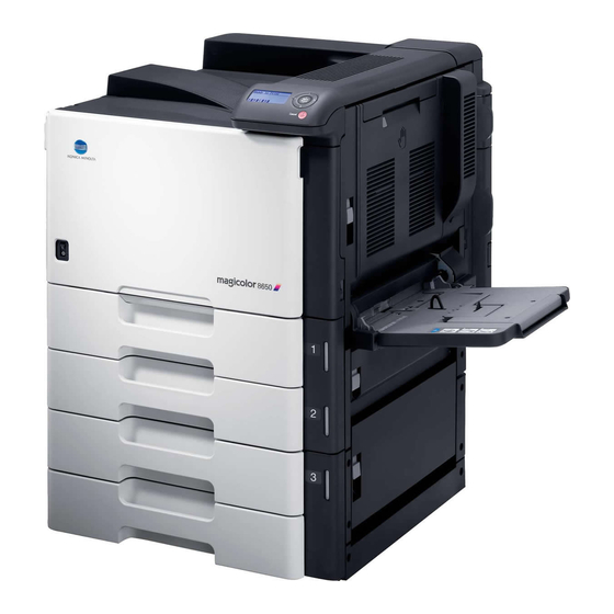
Field Service Ver. 2.0 Nov. 2007 1. System configuration General System configuration 1/2 System front view [13] [12] [11] [10] A02ET2C002DB Main body Output tray OT-602 Mount kit MK-713 Mailbin kit MT-502 Desk DK-505 [10] Punch kit PK-515 Paper feed cabinet PC-106 [11] Saddle stitcher... - Page 43 1. System configuration Field Service Ver. 2.0 Nov. 2007 2/2 System rear view A02ET2C003DA Main body Mount kit MK-711 Hard disk HD-508 Authentication unit (biometric type) AU-101 Security kit SC-503 Authentication unit (IC card type) AU-201 Local interface kit EK-603 Confidential –...
-
Page 44: Product Specifications
Field Service Ver. 2.0 Nov. 2007 2. Product specifications Product specifications A. Type Type Desktop/console *1 printer Printing process Laser electrostatic printing system PC drum type OPC drum: KM-12 (OPC with high mold releasability) Tray 1 : Small roller separation system with torque limiter Tray 2 : Roller separation system with pick-up mechanism Paper feeding... - Page 45 2. Product specifications Field Service Ver. 2.0 Nov. 2007 B. Functions Warm-up time (at ambient temperature of 23° C/73.4° F and 75 sec. or less (Monochrome print, Color print) rated source voltage) Image loss Leading edge: 4.2 mm (3/16 inch), Trailing edge: 3 mm (1/8 inch), Rear edge: 3 mm (1/8 inch), Front edge: 3 mm (1/8 inch)
- Page 46 Field Service Ver. 2.0 Nov. 2007 2. Product specifications C. Paper Paper source (maximum tray capacity) Type Tray 2 Tray 3 Tray 1 Plain paper ❍ (500 sheets) ❍ (500 sheets) ❍ (150 sheets) (60 to 90 g/m / 16 to 24 lb) ⎯...
-
Page 47: Maintenances
2. Product specifications Field Service Ver. 2.0 Nov. 2007 D. Maintenance Color print 1,800 prints No. of pages printed per month (average) Monochrome print 7,400 prints Color print 4pages/job Standard print mode Monochrome print 4 pages/job Color print C, M, Y, K 5% Standard original density Monochrome print... - Page 48 Field Service Ver. 2.0 Nov. 2007 2. Product specifications G. Print functions Type Built-in type controller PCL5e/c emulation PCL XL Ver. 2.1 emulation Printer language PostScript 3 emulation (3016) XPS Ver. 1.0 1024 MB Hard Disk 60 GB (Option) Ethernet (10Base-T, 100Base-TX or 1,000Base-T) Host interface USB 2.0/1.1 TCP/IP(IPv4/IPv6), BOOTP, ARP, ICMP, DHCP, AutoIP, SNMP, FTP, LPR/LPD, RAW...
- Page 49 2. Product specifications Field Service Ver. 2.0 Nov. 2007 Blank Page Confidential – for internal use only, do not distribute...
-
Page 50: Maintenance
Field Service Ver. 2.0 Nov. 2007 3. Periodical check Maintenance Periodical check Maintenance items NOTE • To determine when the main body and option maintenance items need cleaning or replacing, use the machine management list to check the relevant life counter val- ues. - Page 51 3. Periodical check Field Service Ver. 2.0 Nov. 2007 C. Periodical parts replacement/cleaning 2 (per 200,000-print) Lubri- Descrip- Class Parts to be replaced Check Clean Replace cation tions Paper feed and image ⎯ ● conditions Overall ⎯ ● ● Appearance ●...
- Page 52 Field Service Ver. 2.0 Nov. 2007 3. Periodical check 3.1.2 PC-106/205/406 A. Periodical parts replacement/cleaning 1 (per 300,000-print) Lubri- Descrip- Class Parts to be replaced Check Clean Replace cation tions Paper feed and image ⎯ ● conditions Overall ⎯ ● ●...
-
Page 53: Maintenance Parts
3. Periodical check Field Service Ver. 2.0 Nov. 2007 Maintenance parts • To ensure that the machine produces good prints and to extend its service life, it is rec- ommended that the maintenance jobs described in this schedule be carried out as instructed. -
Page 54: Cleaning Parts
Field Service Ver. 2.0 Nov. 2007 3. Periodical check B. Option Descrip Ref. Actual durable No. Classification Parts name Parts No. cycle *1 tions Page Pick-up roller 300,000 A00J 5636 ## PC-106 PC-205 Feed roller 300,000 A02E F566 ## PC-406 Separation roller 300,000 A00J 5636 ##... -
Page 55: Concept Of Parts Life
3. Periodical check Field Service Ver. 2.0 Nov. 2007 Concept of parts life 3.3.1 Life value of consumables and parts • To check the life counter value of materials and parts, use the machine management list. • Life specification value means an actual life terminated when prints are made under the conditions as defined in the next section, “Conditions for life specifications values.”... -
Page 56: Conditions For Life Specifications Values
Field Service Ver. 2.0 Nov. 2007 3. Periodical check *6: The count condition is different according to the paper length of the sub scanning direction. Paper length of Count value sub scanning direction Less than 216 mm 1 count 216 mm to 432 mm 2 counts 432 mm to 648 mm 3 counts... -
Page 57: Maintenance Procedure (Periodical Check Parts)
3. Periodical check Field Service Ver. 2.0 Nov. 2007 Maintenance procedure (periodical check parts) NOTE • The alcohol described in the cleaning procedure of maintenance represents the isopropyl alcohol. 3.4.1 Cleaning of the electrostatic charger wire A. Periodically cleaning parts/cycle •... -
Page 58: Cleaning Of The Area Around The Waste Toner Collecting Port
Field Service Ver. 2.0 Nov. 2007 3. Periodical check 3.4.3 Cleaning of the area around the waste toner collecting port A. Periodically cleaning parts/cycle • Area around the waste toner collecting port: Every 60,000 prints (upon each call) B. Procedure 1. -
Page 59: Replacing The Paper Feed Tray 2 Feed Roller/Paper Feed Tray 2 Pick-Up Roller
3. Periodical check Field Service Ver. 2.0 Nov. 2007 3.4.5 Replacing the paper feed tray 2 feed roller/paper feed tray 2 pick-up roller A. Periodically replacing parts/cycle • Paper feed tray 2 feed roller: Every 300,000 prints • Paper feed tray 2 pick-up roller: Every 300,000 prints B. - Page 60 Field Service Ver. 2.0 Nov. 2007 3. Periodical check 6. Remove two screws [1], and remove the paper feed tray 2 separation roller assy [2]. A02EF2C007DA 7. Remove four screws [1], and remove the paper feed tray 2 feed roller cover [2].
- Page 61 3. Periodical check Field Service Ver. 2.0 Nov. 2007 9. Remove the C-clip [1], and remove the paper feed tray 2 pick-up roller [2]. A02EF2C010DA 10. Remove the C-clip [1] and the bear- ing [2]. Slide the paper feed tray 2 feed roller assy [3].
-
Page 62: Replacing The Paper Feed Tray 2 Separation Roller Assy
Field Service Ver. 2.0 Nov. 2007 3. Periodical check 3.4.6 Replacing the paper feed tray 2 separation roller assy A. Periodically replacing parts/cycle • Paper feed tray 2 separation roller assy: Every 300,000 prints B. Procedure 1. Slide out the paper feed tray 2. 2. -
Page 63: Replacing The Paper Feed Tray 3 Feed Roller/Paper Feed Tray 3 Pick-Up Roller
3. Periodical check Field Service Ver. 2.0 Nov. 2007 3.4.7 Replacing the paper feed tray 3 feed roller/paper feed tray 3 pick-up roller A. Periodically replacing parts/cycle • Paper feed tray 3 feed roller: Every 300,000 prints • Paper feed tray 3 pick-up roller: Every 300,000 prints B. - Page 64 Field Service Ver. 2.0 Nov. 2007 3. Periodical check 7. Remove four screws [1], and remove the paper feed tray 3 paper feed cover [2]. A02EF2C018DA 8. Remove two C-clips [1] and two bearings [2], and remove the paper feed tray 3 pick-up roller assy [3]. A02EF2C019DA 9.
- Page 65 3. Periodical check Field Service Ver. 2.0 Nov. 2007 10. Remove two C-clips [1] and two bearings [2]. Slide the paper feed tray 3 feed roller [3] in the direction of the arrow. A02EF2C020DA 11. Remove the C-clip [1], and remove the paper feed tray 3 feed roller [2].
-
Page 66: Replacing The Paper Feed Tray 3 Separation Roller Assy
Field Service Ver. 2.0 Nov. 2007 3. Periodical check 3.4.8 Replacing the paper feed tray 3 separation roller assy A. Periodically replacing parts/cycle • Paper feed tray 3 separation roller assy: Every 300,000 prints B. Procedure 1. Slide out the paper feed tray 3. 2. -
Page 67: Replacing The Paper Feed Tray 1 Feed Roller
3. Periodical check Field Service Ver. 2.0 Nov. 2007 3.4.9 Replacing the paper feed tray 1 feed roller A. Periodically replacing parts/cycle • Paper feed tray 1 feed roller: Every 200,000 prints B. Procedure 1. Remove the paper feed tray 1 unit. See P.83 2. - Page 68 Field Service Ver. 2.0 Nov. 2007 3. Periodical check 6. Remove the C-clip [1] and the bear- ing [2]. A02EF2C217DA 7. Remove two C-clips [1] and the bear- ing [2], and remove the paper feed tray 1 feed roller [3]. A02EF2C218DA 8.
-
Page 69: Replacing The Paper Feed Tray 1 Separation Roller Assy
3. Periodical check Field Service Ver. 2.0 Nov. 2007 3.4.10 Replacing the paper feed tray 1 separation roller assy A. Periodically replacing parts/cycle • Paper feed tray 1 separation roller assy: Every 200,000 prints B. Procedure 1. Remove the paper feed tray 1 unit. See P.83 2. -
Page 70: Replacing The Waste Toner Box
Field Service Ver. 2.0 Nov. 2007 3. Periodical check 5. Snap off two C-clips [1], and remove the spring [2] and the guide plate [3]. Remove the paper feed tray 1 sepa- ration roller assy [4]. A02EF2C535DA 6. To reinstall, reverse the order of removal. 3.4.11 Replacing the waste toner box A. -
Page 71: Replacing The Transfer Roller Unit
3. Periodical check Field Service Ver. 2.0 Nov. 2007 C. Reinstall procedure 1. Remove a new waste toner box from its packaging and remove the pack- ing material. 2. Place the waste toner box [1] in posi- tion. A02EF2C506DA 3. Close the front door. 3.4.12 Replacing the transfer roller unit A. -
Page 72: Replacing The Imaging Unit
Field Service Ver. 2.0 Nov. 2007 3. Periodical check 3.4.13 Replacing the imaging unit A. Periodically replacing parts/cycle • Imaging unit Y,M,C : Every 90,000 prints • Imaging unit K : Every 120,000 prints NOTE • Although the procedure shown below is for the replacement of the imaging unit K, use the same procedure to replace other imaging units Y,M,C. - Page 73 3. Periodical check Field Service Ver. 2.0 Nov. 2007 C. Reinstall procedure 1. Remove the imaging unit [1] from its packaging. A02EF2C508DA 2. Peel off the tapes, and then remove the packing materials [1]. A02EF2C509DA 3. Remove the imaging unit [2] from the black protective bag [1].
- Page 74 Field Service Ver. 2.0 Nov. 2007 3. Periodical check 4. Tilt the imaging unit [1] to the left and shake it a little left to right twice. Then, tilt the imaging unit to the right and shake it a little right to left twice. A02EF2C511DA 5.
- Page 75 3. Periodical check Field Service Ver. 2.0 Nov. 2007 7. Align the ▲ mark on the imaging unit with the ▼ mark on the main body. Install the imaging unit [1] into the main body. A02EF2C514DA 8. To remove the protective sheet [1] which guards against PC drum dam- age, slowly pull its tab.
-
Page 76: Replacing The Ozone Filter
Field Service Ver. 2.0 Nov. 2007 3. Periodical check 3.4.14 Replacing the ozone filter A. Periodically replacing parts/cycle • Ozone filter: Every 150,000 prints B. Procedure 1. Grip the handle on the ozone filter [1] and slide it out of the main body. A02EF2C297DA 3.4.15 Replacing the toner cartridge... - Page 77 3. Periodical check Field Service Ver. 2.0 Nov. 2007 C. Reinstall procedure 1. Remove the new toner cartridge [1] from its packaging, and then shake the cartridge up and down 5 to 10 times. A02EF2C518DA 2. Align the toner cartridge [1] with the slots in the machine, and then insert the cartridge until the locking tab locks into place.
-
Page 78: Replacing The Transfer Belt Unit
Field Service Ver. 2.0 Nov. 2007 3. Periodical check 3.4.16 Replacing the transfer belt unit A. Periodically replacing parts/cycle • Transfer belt unit: Every 150,000 prints B. Removal procedure 1. Remove all toner cartridges. See toner cartridge replacement/removal procedure steps 1 through 3. See P.35 2. - Page 79 3. Periodical check Field Service Ver. 2.0 Nov. 2007 C. Reinstall procedure 1. Insert the transfer belt unit [1]. NOTE • Insert the transfer belt unit with care not to allow its docking gear to be damaged by hitting it against the rail or associated part.
-
Page 80: Cleaning Of The Image Transfer Entrance Guide
Field Service Ver. 2.0 Nov. 2007 3. Periodical check 3.4.17 Cleaning of the image transfer entrance guide A. Periodically cleaning parts/cycle • Image transfer entrance guide: When the transfer belt unit is replaced (every 150,000 print) B. Procedure 1. Remove the transfer belt unit. See P.37 2. -
Page 81: Replacing The Fusing Unit
3. Periodical check Field Service Ver. 2.0 Nov. 2007 3.4.19 Replacing the fusing unit CAUTION • The temperature gets high in the vicinity of the fusing unit. You may get burned when you come into contact with the area. Before replacement operations, make sure that more than 20 minutes have elapsed since the power switches were turned off. - Page 82 Field Service Ver. 2.0 Nov. 2007 3. Periodical check 6. Remove two screws [1], and remove the fusing unit [2]. NOTE • When removing the fusing unit, hold the parts shown on the picture on the left so that it would not fall. A02EF2C312DA Confidential –...
-
Page 83: Service Tool
4. Service tool Field Service Ver. 2.0 Nov. 2007 Service tool Service material list Name Shape Material No. Remarks Cleaning pad 000V-18-1 10pcs/1pack A02EF2C526DA ⎯ Isopropyl alcohol A00KF2C506DA Molykote EM-50L grease 4478 7801 ## Used with FS-519 A00KF2C507DA Confidential – for internal use only, do not distribute... -
Page 84: Ce Tool List
Field Service Ver. 2.0 Nov. 2007 4. Service tool CE tool list Tool name Shape Quantity Parts No. Remarks PH window cleaning jig 4038 2083 ## 4038F2C557DA PH window cleaning jig 4038 2084 ## 4038F2C558DA V865400001 Compact flash (blank) 4037F2C601DA *1: Inquire of KMBT about the part number of compact flash in which the firmware data is written. -
Page 85: Print Materials
4. Service tool Field Service Ver. 2.0 Nov. 2007 Print materials 4.3.1 Imaging unit single parts (IU) Parts name Replacing period Imaging unit K 120,000 prints Imaging unit Y 90,000 prints Imaging unit M 90,000 prints Imaging unit C 90,000 prints See P.14 4.3.2 Toner cartridge single parts (T/C) -
Page 86: Firmware Upgrade
Field Service Ver. 2.0 Nov. 2007 5. Firmware upgrade Firmware upgrade Outline • There are two ways to update the firmware: One is by directly connecting with the main body using the compact flash, and the other is by downloading over a network using the Internet ISW. - Page 87 5. Firmware upgrade Field Service Ver. 2.0 Nov. 2007 2. Double-click the firmware data, and specify the directory to be uncompressed, and then uncompress it. A02EF2C277DA NOTE • When old firmware is still left in the specified directory to be uncompressed, delete it before uncompressing.
- Page 88 Field Service Ver. 2.0 Nov. 2007 5. Firmware upgrade 6. Specify the drive of compact flash, which was recognized through the procedure 3, and execute the “mkcf.bat.” (Input the C: \magicolor\card_work>mkcf tmc f (drive number): in the below figure, and push the “Enter”.) A02EF2C278DA 7.
-
Page 89: Firmware Rewriting By Compact Flash
5. Firmware upgrade Field Service Ver. 2.0 Nov. 2007 Firmware rewriting by compact flash • The firmware is updated using the compact flash. 5.3.1 Updating method NOTE • NEVER remove or insert the compact flash card with the machine power turned 1. - Page 90 Field Service Ver. 2.0 Nov. 2007 5. Firmware upgrade 6. Check the message and press the Menu/Select key to start the firmware rewrite. Firmware Update Push [select] Key A02EF2C258DA 7. While the firmware rewrite is in process, the following message appears and LED line blinks in blue.
-
Page 91: Action When Data Transfer Fails
5. Firmware upgrade Field Service Ver. 2.0 Nov. 2007 5.3.2 Action when data transfer fails • If “Failed to Download” appears on the control panel, indicating that rewriting has been unsuccessful (in which case the Start key lights up red), take the following steps. 1. -
Page 92: Updating The Firmware With The Internet Isw
Field Service Ver. 2.0 Nov. 2007 5. Firmware upgrade Updating the firmware with the Internet ISW 5.4.1 Outline • [Internet ISW] is the system where the firmware update instructions are sent to the main body via the control panel so that the main body will automatically receive the latest firm- ware data from the program server over a network. - Page 93 5. Firmware upgrade Field Service Ver. 2.0 Nov. 2007 B. Protocol setting • It performs the setting concerning the protocol (ftp or http) for connecting to the Internet ISW. • When connecting to the program server using a proxy server, perform the setting for a proxy server.
- Page 94 Field Service Ver. 2.0 Nov. 2007 5. Firmware upgrade C. Forwarding access setting • To make the access setting for the program server which stores the firmware data. 1. Select [Service Mode] → [Internet ISW]. 2. Select [ForwardAccessSet], and press the Menu/Select key. ForwardAccessSet User ID Password...
-
Page 95: Firmware Update Procedure
5. Firmware upgrade Field Service Ver. 2.0 Nov. 2007 5.4.4 Firmware update procedure NOTE • When performing the Internet ISW, ask the administrator for permission before- hand. • DO NOT turn OFF the power switch while downloading. A. Update procedure 1. - Page 96 Field Service Ver. 2.0 Nov. 2007 5. Firmware upgrade 12. When Internet ISW is complete successfully, the control panel displays the message as shown in the following illustration. Net Client Result Upgrade successful A02EF2C281DA B. Completed or failed (1) Firmware updated normally 1.
-
Page 97: Error Code List For The Internet Isw
[Service Mode] → [Internet ISW] → [ForwardAccessSet] • If the above process does not solve the problem, inform the corresponding error code to the KONICA MINOLTA. • Check if the following setting is set to “Enable”. [Service Mode] → [Internet ISW] →... - Page 98 • If the above process does not solve the • There is no space for F/W data to be 0x10000104 problem, inform the corresponding downloaded. error code to the KONICA MINOLTA. 0x10000106 • Check sum error File access error • The file downloaded has an error.
- Page 99 5. Firmware upgrade Field Service Ver. 2.0 Nov. 2007 Error code Description Countermeasure Control panel • The area F/W is stored is destroyed, 0x10000108 and another ISW is necessary. The temporary error when running the subset • When starting the Internet ISW in a normal program, the rebooting will start •...
-
Page 100: Firmware Update By Customer
Field Service Ver. 2.0 Nov. 2007 5. Firmware upgrade Firmware update by customer 5.5.1 Outline • This machine allows the firmware update by customer, using the built-in FTP server fea- ture. A. Procedure 1. Store THAMESMC.bin file in any desired place in the PC. 2. - Page 101 5. Firmware upgrade Field Service Ver. 2.0 Nov. 2007 9. Press the Menu/Select key on the control panel. The machine starts downloading the data. Firmware Update After Send F/W Push [select] Key [Cancel] Abort A02EF2C254DA 10. Make sure that the message “Download Completed” appears. Then, turn OFF and then turn ON the power switch.
-
Page 102: Other
Field Service Ver. 2.0 Nov. 2007 6. Other Other Disassembly/adjustment prohibited items A. Paint-locked screws NOTE • To prevent loose screws, a screw lock in blue or green series color is applied to the screws. • The screw lock is applied to the screws that may get loose due to the vibrations and loads created by the use of machine or due to the vibrations created during transportation. -
Page 103: Disassembly/Assembly/Cleaning List (Other Parts)
6. Other Field Service Ver. 2.0 Nov. 2007 Disassembly/assembly/cleaning list (other parts) 6.2.1 Disassembly/assembly parts list Section Part name Ref. page Front door P.65 Upper front cover P.66 Right front cover/1 P.67 Right front cover/2 P.67 Left cover P.69 Rear left cover P.70 Exit cover P.70... - Page 104 Field Service Ver. 2.0 Nov. 2007 6. Other Section Part name Ref. page PH relay board (PHREYB) P.95 DC power supply (DCPU) P.97 Printer control board (PRCB) P.99 MFP board (MFPB) P.101 High voltage unit (HV) P.105 Service EEPROM board (SV ERB) P.106 PWBs SODIMM/1, SODIMM/2...
-
Page 105: Cleaning Parts List
6. Other Field Service Ver. 2.0 Nov. 2007 6.2.2 Cleaning parts list Section Part name Ref. page Transfer belt unit P.127 Processing section PH window P.127 Paper feed tray 2 feed roller P.128 Paper feed tray 2 Paper feed tray 2 pick-up roller P.128 Paper feed tray 2 separation roller P.128... -
Page 106: Disassembly/Assembly Procedure
Field Service Ver. 2.0 Nov. 2007 6. Other Disassembly/assembly procedure 6.3.1 Front door 1. Open the front door. 2. Remove two screws [1] and the sup- pression plate [2]. A02EF2C317DA 3. Remove the PH window cleaning jig [1]. A02EF2C318DA Confidential – for internal use only, do not distribute... -
Page 107: Upper Front Cover
6. Other Field Service Ver. 2.0 Nov. 2007 4. Slide the pins [1] in the direction of the arrow and remove it. 5. Remove the front door [2]. A02EF2C320DA 6.3.2 Upper front cover 1. Open the front door. 2. Open the right door. 3. -
Page 108: Right Front Cover/1
Field Service Ver. 2.0 Nov. 2007 6. Other 6.3.3 Right front cover/1 1. Open the front door. 2. Open the right door. 3. Remove the upper front cover. See P.66 4. Remove four screws [1], and remove the right front cover/1 [2]. A02EF2C324DA 6.3.4 Right front cover/2... - Page 109 6. Other Field Service Ver. 2.0 Nov. 2007 5. Remove three screw [1], and remove the paper empty indicator board assy [2]. A02EF2C327DA 6. Remove two empty display lenses [1]. A02EF2C328DA Confidential – for internal use only, do not distribute...
-
Page 110: Left Cover
Field Service Ver. 2.0 Nov. 2007 6. Other 6.3.5 Left cover 1. Open the front door. 2. If the optional finisher FS-519 is mounted, remove it. See P.20 of the FS-519/PK-515/OT- 602 service manual. NOTE • After removing the finisher FS-519, remove four screws [1] and mount- ing plate [2]. -
Page 111: Rear Left Cover
6. Other Field Service Ver. 2.0 Nov. 2007 6.3.6 Rear left cover 1. Open the front door. 2. Remove the ozone filter. See P.35 3. Remove the left cover. See P.69 4. Remove four screws [1], and remove the rear left cover [2]. A02EF2C330DA 6.3.7 Exit cover... -
Page 112: Rear Right Cover/1
Field Service Ver. 2.0 Nov. 2007 6. Other 6.3.8 Rear right cover/1 1. Open the right door. 2. Open the rear right door [1], 3. Remove five screws [2], and remove the rear right cover/1 [3], A02EF2C334DA 6.3.9 Rear right cover/2 1. -
Page 113: Paper Feed Tray 1 Front Cover, Paper Feed Tray 1 Rear Cover
6. Other Field Service Ver. 2.0 Nov. 2007 6.3.10 Paper feed tray 1 front cover, Paper feed tray 1 rear cover 1. Open the vertical transport door. 2. Remove the rear right cover/2. See P.71 3. Remove two screws [1], and remove the paper feed tray 1 front cover [2] and the paper feed tray 1 rear cover [3]. -
Page 114: Rear Cover/1, Rear Cover/2
Field Service Ver. 2.0 Nov. 2007 6. Other 6.3.12 Rear cover/1, Rear cover/2. 1. Remove four screws [1], and remove the rear cover/2 [2]. 2. Remove four screws [3], and remove the rear cover/1 [4]. A02EF2C341DA 6.3.13 Lower rear cover/1, lower rear cover/2 1. -
Page 115: Control Panel Assy
6. Other Field Service Ver. 2.0 Nov. 2007 6.3.15 Control panel assy 1. Open the right door. 2. Open the exit cover. 3. Remove the upper front cover. See P.66 4. Disconnect the connector [1], Remove three screws [2], and remove the control panel assy [3]. -
Page 116: Paper Feed Tray 2
Field Service Ver. 2.0 Nov. 2007 6. Other 6.3.17 Paper feed tray 2 1. Slide out the tray 2. 2. Remove two screws [1], and metal plate [2], and remove the paper feed tray 2 [3]. A02EF2C418DA 6.3.18 Paper feed tray 3 1. -
Page 117: Front Cover
6. Other Field Service Ver. 2.0 Nov. 2007 6.3.19 Front cover 1. Slide out the paper feed tray 2. 2. Remove the front door. See P.65 3. Remove the left cover. See P.69 4. Remove the toner cartridges (C, M, Y, K). See P.35 5. - Page 118 Field Service Ver. 2.0 Nov. 2007 6. Other 10. Disconnect two connectors [1]. A02EF2C071DA 11. Remove five screws [1]. A02EF2C350DA 12. Unhook six tabs [1], and disconnect the connector [2] from the front cover. 13. Remove the front cover [3]. A02EF2C352DA Confidential –...
-
Page 119: Ph Unit
6. Other Field Service Ver. 2.0 Nov. 2007 6.3.20 PH unit CAUTION • Do not replace the printer head unit while the power is ON. Laser beam generated during the above mentioned activity may cause blindness. • Do not disassemble or adjust the printer head unit. Laser beam generated during the above mentioned activity may cause blindness. - Page 120 Field Service Ver. 2.0 Nov. 2007 6. Other 5. Unhook the tab [1], and remove the gear [2] of the PH unit. NOTE • This step is not needed when removing PH unit (Black) that does not have a gear. A02EF2C076DA 6.
- Page 121 6. Other Field Service Ver. 2.0 Nov. 2007 Remove the boss [1] at the rear side of the PH unit from the locating hole [2]. NOTE • Since the back of the PH unit is pushed to the right with the two plate springs [3], remove it by tilting the backside of the PH unit to the left as shown in the left illustration.
- Page 122 Field Service Ver. 2.0 Nov. 2007 6. Other 2. Push the PH unit [1] along the right side line of PH unit installation plate all the way and fit it into the plate spring [2]. 3. Make sure that the two bosses [3] at front and rear side of the PH unit fit in the locating hole [4].
- Page 123 6. Other Field Service Ver. 2.0 Nov. 2007 5. Reinstall the gear [1]. NOTE • Make sure that the gear claw is fit 6. Connect the connector and the flat cable. NOTE • Make sure the harness is installed along with the harness guide. 7.
-
Page 124: Paper Feed Tray 1 Unit
Field Service Ver. 2.0 Nov. 2007 6. Other 6.3.21 Paper feed tray 1 unit 1. Open the vertical transport door. 2. Remove the rear right cover/2. See P.73 3. Remove the paper feed tray 1 front cover and the paper feed tray 1 rear cover. See P.72 4. -
Page 125: Main Drive Unit
6. Other Field Service Ver. 2.0 Nov. 2007 6.3.22 Main drive unit 1. Remove the transfer belt unit. See P.37 2. Remove the high voltage unit. See P.105 3. Remove the Color PC motor. See P.111 4. Remove the transport motor. See P.111 5. - Page 126 Field Service Ver. 2.0 Nov. 2007 6. Other 9. Remove eight screws [1], and slide out the main drive unit [2]. A02EF2C089DA 10. Remove the E-ring [1], and remove the gear [2]. A02EF2C090DA 11. Disconnect the connector [1], and remove the harness from five wire saddles [2].
-
Page 127: Transport Drive Unit
6. Other Field Service Ver. 2.0 Nov. 2007 6.3.23 Transport drive unit 1. Remove the paper feed tray 1 tray unit. See P.83 2. Remove the main drive unit. See P.84 3. Remove the lower rear cover/1 and the lower rear cover/2. See P.73 4. - Page 128 Field Service Ver. 2.0 Nov. 2007 6. Other 9. Remove two screws [1], and remove the rear handle cover [2]. A02EF2C095DA 10. Disconnect two connectors [1], and remove the harness from six wire saddles [2] and the edge cover [3]. A02EF2C365DA 11.
- Page 129 6. Other Field Service Ver. 2.0 Nov. 2007 12. Disconnect two connectors [1], and remove the harness from the edge cover [2]. A02EF2C358DA 13. Remove each six tabs [1] and two hooks [2]. 14. Remove two wire guides [3]. A02EF2C100DA 15.
-
Page 130: Fusing Drive Unit
Field Service Ver. 2.0 Nov. 2007 6. Other 6.3.24 Fusing drive unit 1. Remove the transfer belt unit. See P.37 2. Remove the fusing unit. See P.40 3. Remove the fusing motor. See P.112 4. Remove the harness from two har- ness guides [1]. - Page 131 6. Other Field Service Ver. 2.0 Nov. 2007 9. Remove four screws [1], and remove the fusing rear guide [2] and the shaft cover [3]. A02EF2C105DA 10. Remove the spring [1] from the pro- trusion [2]. A02EF2C106DA 11. Unhook the tab [1]. Pull the fusing drive unit [2] to the front and remove it.
-
Page 132: Hopper Drive Unit (C/K, Y/M)
Field Service Ver. 2.0 Nov. 2007 6. Other 6.3.25 Hopper drive unit (C/K, Y/M) A. Hopper drive unit (C/K) 1. Remove the main drive unit. See P.84 2. Disconnect the connector [1]. 3. Remove four screws [2], and remove the hopper drive unit (C/K) [3]. A02EF2C361DA B. -
Page 133: Right Door Assy
6. Other Field Service Ver. 2.0 Nov. 2007 6.3.26 Right door assy 1. Remove the lower rear cover/1 and the lower rear cover/2. See P.73 2. Remove the paper feed tray 1 unit. See P.83 3. Remove the high voltage unit. See P.105 4. - Page 134 Field Service Ver. 2.0 Nov. 2007 6. Other 10. Open the right door, and remove the collar [1], the spring [2] and the shoulder screw [3]. A02EF2C114DA 11. Disconnect two connectors [1], and remove the harness from six wire saddles [2] and the edge cover [3]. A02EF2C365DA 12.
- Page 135 6. Other Field Service Ver. 2.0 Nov. 2007 14. Remove seven screws [1] and remove the rear handle assy [2]. A02EF2C368DA 15. Disconnect two connectors [1], and remove the harness from the edge cover [2]. A02EF2C369DA 16. Remove two wire saddles [1] and two connectors [2].
-
Page 136: Ph Relay Board (Phreyb)
Field Service Ver. 2.0 Nov. 2007 6. Other 17. Remove the screw [1], and remove two shafts [2]. 18. Remove the right door assy [3]. A02EF2C371DA 6.3.27 PH relay board (PHREYB) 1. Remove the front cover. See P.76 2. Remove the transfer belt unit. See P.37 3. - Page 137 6. Other Field Service Ver. 2.0 Nov. 2007 6. Remove two screws [1] each, and remove the imaging unit roll assy [2] of each color. A02EF2C129DA 7. Remove all the connectors and the flat cables on the PH relay board. A02EF2C130DA 8.
-
Page 138: Dc Power Supply (Dcpu)
Field Service Ver. 2.0 Nov. 2007 6. Other 9. Remove two screws [1] and six tabs [2], and remove the PH relay board [3]. A02EF2C132DA 6.3.28 DC power supply (DCPU) CAUTION • Remove the DC power supply after six minutes or more have passed since the power plug was disconnected. - Page 139 6. Other Field Service Ver. 2.0 Nov. 2007 8. Remove the harness from seven wire saddles [1] and two edge covers [2]. A02EF2C374DA 9. Remove all the connectors on the DC power supply [1]. A02EF2C375DA 10. Remove four screws [1], and remove the DC power supply [2].
-
Page 140: Printer Control Board (Prcb)
Field Service Ver. 2.0 Nov. 2007 6. Other 6.3.29 Printer control board (PRCB) 1. Open the front door. 2. Remove the rear left cover. See P.70 3. Remove the upper rear cover. See P.72 4. Remove seven screws [1], and remove the protective shield/2 [2]. - Page 141 6. Other Field Service Ver. 2.0 Nov. 2007 8. Disconnect the connector [1], remove two screws [2], and remove the metal plate [3]. A02EF2C384DA 9. Remove all the connectors on the printer control board [1]. A02EF2C385DA 10. Remove six screws [1]. Slide the printer control board [2] in the direc- tion of the arrow and remove it.
-
Page 142: Mfp Board (Mfpb)
Field Service Ver. 2.0 Nov. 2007 6. Other 6.3.30 MFP board (MFPB) 1. Remove the rear left cover. See P.70 2. Remove the upper rear cover. See P.72 3. Remove the protective shield/1 and the protective shield/2. See the steps 1 to 5 of printer control board removing procedure. See P.99 4. - Page 143 6. Other Field Service Ver. 2.0 Nov. 2007 10. Remove five screws [1] and six bolts [2], and remove the metal plate [3]. A02EF2C390DA 11. Remove twelve screws [1] of the MFP board. 12. Slide the MFP board [2] in the direc- tion of the arrow, disconnect the con- nector [3], and remove the MFP board.
-
Page 144: Pwb Box
Field Service Ver. 2.0 Nov. 2007 6. Other 6.3.31 PWB box 1. Remove the rear left cover. See P.70 2. Remove the upper rear cover. See P.72 3. Remove the rear right cover/1 and the rear right cover/2. See P.71 4. - Page 145 6. Other Field Service Ver. 2.0 Nov. 2007 10. Remove five screws [1], and remove the metal plate [2]. A02EF2C396DA 11. Remove eleven screws [1]. While raising the PWB box [2] a little, slide it to the left. Then, remove the cool- ing fan motor/2 [3].
-
Page 146: High Voltage Unit (Hv)
Field Service Ver. 2.0 Nov. 2007 6. Other 6.3.32 High voltage unit (HV) 1. Remove the PWB box See P.103 2. Disconnect seven connectors [1]. A02EF2C154DA 3. Remove five screws [1] and the tab [2], and remove the high voltage unit [3]. -
Page 147: Service Eeprom Board (Sv Erb)
6. Other Field Service Ver. 2.0 Nov. 2007 6.3.33 Service EEPROM board (SV ERB) 1. Remove the rear cover/1 and the rear cover/2 See P.73 2. Remove the protective shield/1 and the protective shield/2. See the steps 1 to 5 of printer board removing procedure. - Page 148 Field Service Ver. 2.0 Nov. 2007 6. Other Order Items that require readjustment in the Service mode Ref. page System Settings Change WarmupTime P.217 MachineAdjustment Exhaust Fan Delay P.235 System Settings Unit Replacement P.211 IU Yield Setting P.216 NOTE • After replacing the service EEPROM board, be sure to make the above listed adjustments before the first warm-up is made.
-
Page 149: Sodimm/1, Sodimm/2
6. Other Field Service Ver. 2.0 Nov. 2007 6.3.34 SODIMM/1, SODIMM/2 1. Remove the protective shield/1 and the protective shield/2. See the steps 1 to 5 of printer control board removing procedure. See P.99 2. Remove the SODIMM/1 [1] and SODIMM/2 [2] on the MFP board. -
Page 150: Nvram Board (Nrb)
Field Service Ver. 2.0 Nov. 2007 6. Other 6.3.36 NVRAM board (NRB) 1. Remove the protective shield/1 and the protective shield/2. See the steps 1 to 5 of printer control board removing procedure. See P.99 2. Remove the NVRAM board [2] on the MFP board [1]. -
Page 151: Paper Feed Tray 3 Paper Fd Size Detect Board (Psdtb/2)
6. Other Field Service Ver. 2.0 Nov. 2007 7. Remove the lever [1], and remove the paper feed tray 2 paper FD size detect board [2]. 9J06F2C566DA 6.3.38 Paper feed tray 3 paper FD size detect board (PSDTB/2) 1. Remove the paper feed tray 2. See P.75 2. -
Page 152: Transport Motor (M1)
Field Service Ver. 2.0 Nov. 2007 6. Other 7. Remove the lever [1], and remove the paper feed tray 3 paper FD size detect board [2]. 9J06F2C566DA 6.3.39 Transport motor (M1) 1. Remove the PWB box. See P.103 2. Remove four screws [1], disconnect the connector [2], and remove the transport motor [3]. -
Page 153: Fusing Motor (M5)
6. Other Field Service Ver. 2.0 Nov. 2007 6.3.41 Fusing motor (M5) 1. Remove the PWB box. See P.103 2. Remove five screws [1], and remove the bracket [2]. A02EF2C401DA 3. Remove four screws [1], disconnect the connector [2], and remove the fusing motor [3]. -
Page 154: Switchback Motor (M6)
Field Service Ver. 2.0 Nov. 2007 6. Other 6.3.42 Switchback motor (M6) 1. Remove the upper rear cover. See P.72 2. Remove the rear right cover/1. See P.71 3. Remove the fusing drive unit. See P.89 4. Disconnect the connector [1]. 5. -
Page 155: Duplex Transport Motor (M7)
6. Other Field Service Ver. 2.0 Nov. 2007 8. Disconnect the connector [1]. 9. Remove two screws [2], and remove the switchback motor [3]. NOTE • Care should be taken to avoid let- ting the lever [4] hit the housing and be damaged. -
Page 156: Fusing Retraction Motor (M12)
Field Service Ver. 2.0 Nov. 2007 6. Other 6.3.44 Fusing retraction motor (M12) 1. Remove the upper rear cover. See P.72 2. Remove the protective shield/1 and the protective shield/2. See the steps 1 to 5 of printer control board removing procedure. See P.99 3. -
Page 157: Paper Feed Tray 2 Lift-Up Motor (M8)
6. Other Field Service Ver. 2.0 Nov. 2007 6.3.45 Paper feed tray 2 lift-up motor (M8) 1. Remove the paper feed tray 2. See P.75 2. Remove the paper feed tray 3. See P.75 3. Remove the right front cover/2. See P.67 4. -
Page 158: Paper Feed Tray 3 Lift-Up Motor (M9)
Field Service Ver. 2.0 Nov. 2007 6. Other 10. Remove three screws [1], and remove the paper feed tray 2 lift-up motor [2]. A02EF2C182DA 6.3.46 Paper feed tray 3 lift-up motor (M9) 1. Remove the paper feed tray 2. See P.75 2. - Page 159 6. Other Field Service Ver. 2.0 Nov. 2007 7. Remove the harness from five wire saddles [1] and the edge cover [2]. A02EF2C542DA 8. Disconnect the connector [1], and remove the harness from the edge cover [2]. 9. Remove three screws [3], take out the paper feed tray 3 lift-up motor assy [4].
-
Page 160: Toner Supply Motor/Ck (M3)
Field Service Ver. 2.0 Nov. 2007 6. Other 6.3.47 Toner supply motor/CK (M3) 1. Remove the PWB box. See P.103 2. Disconnect the connector [2], remove two screws [1], and remove the toner supply motor/CK [3]. A02EF2C412DA 6.3.48 Toner supply motor/YM (M4) 1. -
Page 161: Paper Feed Tray 1 Paper Feed Clutch (Cl1)
6. Other Field Service Ver. 2.0 Nov. 2007 6.3.49 Paper feed tray 1 paper feed clutch (CL1) 1. Remove the paper feed tray 2 paper feed assy. See the steps 1 to 4 of paper feed tray 2 feed roller/paper feed tray 2 pick-up roller removing procedure. -
Page 162: Paper Feed Tray 3 Vertical Transport Clutch (Cl3)
Field Service Ver. 2.0 Nov. 2007 6. Other 6.3.50 Paper feed tray 3 vertical transport clutch (CL3) 1. Remove the paper feed tray 3 paper feed assy. See the steps 1 to 5 of paper feed tray 3 feed roller/paper feed tray 3 pick-up roller removing procedure. -
Page 163: Paper Feed Tray 3 Paper Feed Clutch (Cl2)
6. Other Field Service Ver. 2.0 Nov. 2007 6.3.51 Paper feed tray 3 paper feed clutch (CL2) 1. Remove the tray 3 paper feed assy. See the steps 1 to 5 of paper feed tray 3 feed roller/paper feed tray 3 pick-up roller removing procedure. -
Page 164: Transfer Belt Retraction Clutch (Cl7)
Field Service Ver. 2.0 Nov. 2007 6. Other 6.3.53 Transfer belt retraction clutch (CL7) 1. Remove the fusing drive unit. See P.89 2. Disconnect the connector [2], remove three E-rings [1] and five screws [3], and remove the metal plate [4]. A02EF2C195DA 3. -
Page 165: Tim. Roller Clutch (Cl6)
6. Other Field Service Ver. 2.0 Nov. 2007 3. Remove three screws [1] and the E- ring [2], and remove the developing clutch/K cover [3]. A02EF2C198DA 4. Disconnect the connector [1], and remove the developing clutch/K [2]. A02EF2C199DA 6.3.55 Tim. roller clutch (CL6) 1. -
Page 166: Idc Registration Sensor/Mk (Idcs/Mk), Idc Registration Sensor/Yc (Idcs/Yc)
Field Service Ver. 2.0 Nov. 2007 6. Other 6.3.56 IDC registration sensor/MK (IDCS/MK), IDC registration sensor/YC (IDCS/YC) 1. Remove the transfer belt unit. See P.37 2. Remove the paper feed tray 1 unit. See P.83 3. Remove the shoulder screw [1]. A02EF2C201DA 4. - Page 167 6. Other Field Service Ver. 2.0 Nov. 2007 7. Disconnect three connectors [1], and remove the vertical transport unit [2]. A02EF2C204DA 8. Remove three screws [1], and remove the metal plate [2]. NOTE • Both end screws has a spacer. Remove the screws, being careful not to drop the spacers.
-
Page 168: Cleaning Procedure
Field Service Ver. 2.0 Nov. 2007 6. Other Cleaning procedure NOTE • The alcohol described in the cleaning procedure represents the ethanol isopropyl alcohol. 6.4.1 Transfer belt unit 1. Remove the transfer belt unit. See P.37 2. Using a cleaning pad, wipe the trans- fer belt [1]. - Page 169 6. Other Field Service Ver. 2.0 Nov. 2007 6.4.3 Paper feed tray 2 feed roller, paper feed tray 2 pick-up roller, paper feed tray 1 separation roller 1. Remove the paper feed tray 2paper feed assy. See the steps 1 to 4 of paper feed tray 2 feed roller/paper feed tray 2 pick-up roller removing procedure.
-
Page 170: Separation Roller
Field Service Ver. 2.0 Nov. 2007 6. Other 6.4.4 Paper feed tray 3 feed roller, paper feed tray 3 pick-up roller, paper feed tray 3 separation roller 1. Remove the paper feed tray 3 paper feed assy. See the steps 1 to 5 of paper feed tray 3 feed roller/tray 2 pick-up roller removing proce- dure. -
Page 171: Separation Roller
6. Other Field Service Ver. 2.0 Nov. 2007 6.4.5 Paper feed tray 3 transport roller 1. Open the vertical transport door. 2. Using a cleaning pad dampened with alcohol, wipe the paper feed tray 3 transport roller [1] clean of dirt. A02EF2C414DA 6.4.6 Paper feed tray 1 feed roller... -
Page 172: Adjustment/Setting
Field Service Ver. 2.0 Nov. 2007 7. How to use the adjustment section Adjustment/Setting How to use the adjustment section • “Adjustment/Setting” contains detailed information on the adjustment items and proce- dures for this machine. • Throughout this “Adjustment/Setting,” the default settings are indicated by “ ”. Advance checks •... -
Page 173: Utility Mode
8. Utility Mode Field Service Ver. 2.0 Nov. 2007 Utility Mode Control Panel A02EF3E019DA Name Description The machine’s current status is indicated by the color and lighting/flashing of the indicator. Flashing in blue: Printing normally LED line Lit in blue: Operable, printable Flashing in red: Warning Lit in red: Inoperable (Stopping operating) •... -
Page 174: Utility Mode Function Tree
Field Service Ver. 2.0 Nov. 2007 8. Utility Mode Utility Mode function tree * The function tree is shown to comply with the format displayed on the screen. NOTE • Keys displayed on screens are different depending on the setting. •... - Page 175 8. Utility Mode Field Service Ver. 2.0 Nov. 2007 Utility Mode Ref. page User Settings System Output Tray 1 to Bin 5 P.151 Settings Settings Assignment ** Tray 2 to Bin 6 Printer Basic PDL Setting P.151 Settings Settings Number of Copies P.151 OriginalDirection P.151...
- Page 176 Field Service Ver. 2.0 Nov. 2007 8. Utility Mode Utility Mode Ref. page System Network TCP/IP IPv6 IPv6 Setting P.159 Settings Settings Auto IPv6 Setting Global Address Prefix Length Gateway Address LinkLocal Address DNS Server ServerAutoObtain P.160 PriorityDNSServer Secondary DNS 1 Secondary DNS 2 IP Filtering IP Filter(Permit)
- Page 177 8. Utility Mode Field Service Ver. 2.0 Nov. 2007 Utility Mode Ref. page System Network HTTP Server IPP Auth. Auth. Method P.167 Settings Settings Setting User Name P.167 Password P.167 realm P.167 Accept IPP jobs P.167 Support Info. Print Job P.167 Valid Job Cancel Job...
- Page 178 Field Service Ver. 2.0 Nov. 2007 8. Utility Mode Utility Mode Ref. page System Network SNMP SNMP v3 ReadUser Auth-password P.172 Settings Settings Setting Settings Priv-password WriteUser Write User P.173 Settings Name Security Level P.173 Auth-password P.173 Priv-password Encrypt Algorithm P.173 Auth.
- Page 179 8. Utility Mode Field Service Ver. 2.0 Nov. 2007 Utility Mode Ref. page Admin. Security Security Prohibit Mode Setting P.180 Settings Settings Details Functions #of Auth Attempts Release Release Time SecurePrintAccess P.181 PrintDataCapture P.181 DeleteJobHistory P.181 Audit Log Audit Log Setting P.182 OverwriteAuditLog Delete Audit Log...
- Page 180 Field Service Ver. 2.0 Nov. 2007 8. Utility Mode Utility Mode Ref. page Admin. Expert Density Thick/Yellow P.194 Settings Adjustment Adjustment Thick/Magenta Thick/Cyan Thick/Black BlackImageDensity P.194 Stabilization Initialize+Stabi. P.194 StabilizationOnly P.195 ColorRegistration P.196 Test Pattern Gradation Pattern P.197 Halftone Pattern P.197 Option HDD Installation...
-
Page 181: Utility Mode Function Setting Procedure
8. Utility Mode Field Service Ver. 2.0 Nov. 2007 Utility Mode function setting procedure 8.3.1 Procedure Cancel key Display panel Menu/Select key A02EF3E019DA A. Job Operation 1. Make sure that the default screen (Ready to Print) is being displayed, and press the Menu/Select key on the control panel. -
Page 182: Meter Count
Field Service Ver. 2.0 Nov. 2007 8. Utility Mode Meter Count • The function is not available if No. 60 is “Disabled”, or “Enabled” but the serial number is yet to be entered, as accessed through [Service Mode] → [System Settings] → [Soft- wareSWSetting]. - Page 183 8. Utility Mode Field Service Ver. 2.0 Nov. 2007 E. Annotation User Box Function/User • To print or delete the document saved in the Annotation User Box. 1. Select the box to be used. Setting/ 2. Enter the “password” of the box to be used. Procedure 3.
-
Page 184: Settings In Paper Tray
Field Service Ver. 2.0 Nov. 2007 8. Utility Mode Settings in Paper Tray • It sets the paper type of for each tray. A. Tray 1 Functions • To set the paper size and paper type for the paper loaded in the tray 1. Setting/ <Paper Size>... - Page 185 8. Utility Mode Field Service Ver. 2.0 Nov. 2007 E. Tray 5 Functions • To set the paper type of the paper loaded in tray 5. • The function is not available when the LCT is mounted. • Set wide paper size only when wide paper is to be used. Setting/ <Wide Paper Size>...
-
Page 186: User Setting Function Setting Procedure
Field Service Ver. 2.0 Nov. 2007 8. Utility Mode User setting function setting procedure 8.7.1 Print Reports Functions • To output the report or Demo Page concerning the print setting. • To check the setting concerning the printer. • The types of report available for output are as follows. Configuration : The list of printer setting will be output. - Page 187 8. Utility Mode Field Service Ver. 2.0 Nov. 2007 (3) Counter Information/Paper Information • The total number of pages that have been printed is counted and displayed based on the description shown in the following table. <Counter information list> Types of count Contents Count timing •...
- Page 188 Field Service Ver. 2.0 Nov. 2007 8. Utility Mode (4) Coverage Information • Each coverage information is calculated and displayed based on the description shown in the following table. <Coverage information list> Coverage information Contents • Individual average dot coverage of four colors (YMCK) in the cur- rent toner cartridges is calculated on an A4 basis.
-
Page 189: Consumables
8. Utility Mode Field Service Ver. 2.0 Nov. 2007 (5) How to read consumable/periodic replacement parts (units) counter informa- tion. • The lower left part of the statistics page shows numerical values that represent consum- able/periodic replacement parts (units) counter information. The table below explains counter information that is provided by each numerical data. - Page 190 Field Service Ver. 2.0 Nov. 2007 8. Utility Mode (2) Sleep Mode Setting Functions • To select whether or not to allow entry into the sleep mode. • “Restrict” will only be displayed when [Don’t go to Sleep] in Service Mode is set. Setting/ •...
- Page 191 8. Utility Mode Field Service Ver. 2.0 Nov. 2007 (3) Auto Tray Switch Functions • To set whether to automatically switch to another tray with same size paper when the paper feed tray runs out of paper during printing. • To switch the paper feed tray automatically. Setting/ •...
-
Page 192: Printer Settings
Field Service Ver. 2.0 Nov. 2007 8. Utility Mode (4) Shift Each Job • It will be displayed only when the optional finisher FS-519 or FS-609 is mounted. Functions • To set whether to offset each job when paper is printed using the finisher or job sep- arator. - Page 193 8. Utility Mode Field Service Ver. 2.0 Nov. 2007 (4) Spool Setting Functions • To set whether to store the print data to HDD when receiving the next job during RIP process of the current job. Setting/ • The default setting is ON. Procedure “ON”...
- Page 194 Field Service Ver. 2.0 Nov. 2007 8. Utility Mode B. Paper Settings (1) Paper Tray Functions • To set the paper feed tray when not specified by the printer driver during PC printing. • To use when paper feed tray cannot be specified by the printer driver when printing from Windows DOS, etc.
- Page 195 8. Utility Mode Field Service Ver. 2.0 Nov. 2007 (6) Punch • The menu is available only when the optional finisher FS-519/FS-609 and punch kit PK- 515/PK-501 is mounted. Functions • To select whether to make punch-holes or not when not specified by the printer driver during PC printing.
- Page 196 Field Service Ver. 2.0 Nov. 2007 8. Utility Mode (4) Pitch Functions • To set the number of lines per page for printing the text data. • To change the number of lines per page for printing the text data. Setting/ •...
- Page 197 8. Utility Mode Field Service Ver. 2.0 Nov. 2007 E. XPS Setting (1) Verify XPS Sign. Functions • Selects whether to verify digital signatures attached to XPS (XML Paper Specifica- tion) files when printing the files. • When digital signature verification is selected, files with invalid digital signatures are not printed.
-
Page 198: System Settings Function Setting Procedure
Field Service Ver. 2.0 Nov. 2007 8. Utility Mode System settings function setting procedure 8.8.1 System Settings A. Date/Time Settings Functions • To set the date/time and the time zone to start the clock. • To change settings concerning the date/time. Setting/ •... -
Page 199: Network Settings
8. Utility Mode Field Service Ver. 2.0 Nov. 2007 (2) Counter List • This function is not available if user authentication or account track is not to be imple- mented. Functions • To print the user counter and account track counter. •... - Page 200 Field Service Ver. 2.0 Nov. 2007 8. Utility Mode (2) IP Setting Functions • To set whether to enter the IP address directly or to obtain it automatically. • To change the method for setting the IP address. Setting/ • The default setting is Auto Setting. Procedure Manual Input “Auto Setting”...
- Page 201 8. Utility Mode Field Service Ver. 2.0 Nov. 2007 (4) DNS Server Functions • To set whether or not to enable the auto obtaining of the DNS server address. • To set the priority/secondary DNS server. • To enter priority/secondary DNS server. Setting/ <Server Auto Obtain>...
- Page 202 Field Service Ver. 2.0 Nov. 2007 8. Utility Mode <IKE Setting> Functions • To make the settings that relate to IKE (Internet Key Exchange) protocol which is used for IPsec communication. • Settings can be made independently for four different sets (Group 1 to 4). Setting/ <Group>...
- Page 203 8. Utility Mode Field Service Ver. 2.0 Nov. 2007 <SA Setting> Functions • To make the settings that relate to IPsec SA (Security Association) which is used for IPsec communication. • Settings can be made independently for eight different sets (Group 1 to 8). Setting/ <Group Set Number>...
- Page 204 Field Service Ver. 2.0 Nov. 2007 8. Utility Mode <Peer> Functions • To register destinations used for IPsec communication. • Settings can be made independently for different ten sets (Group 1 to 10). Setting/ <Peer> Procedure • Among Group 1 to 10, select a group where settings are made. •...
- Page 205 8. Utility Mode Field Service Ver. 2.0 Nov. 2007 (9) DNS Domain Functions • To set whether or not to enable the auto obtaining for the DNS domain name. • To set the DNS default domain name. • To set the DNS search domain name. •...
- Page 206 Field Service Ver. 2.0 Nov. 2007 8. Utility Mode (2) NetWare Print NOTE • When the setting is changed, turn off the power switch and turn it on again more than 10 seconds after. Functions • To set whether to use the NetWare print mode. •...
- Page 207 8. Utility Mode Field Service Ver. 2.0 Nov. 2007 <Pserver: NDS Tree Name> Functions • To set the NDS tree name (name to login). • To set the NDS tree name. Setting/ • Enter the NDS tree name (up to 63 characters) using keys, and press the Procedure Menu/Select key.
- Page 208 Field Service Ver. 2.0 Nov. 2007 8. Utility Mode (3) IPP Setting Functions • To set whether to enable or disable IPP (Internet Printing Protocol) setting. Setting/ • The default setting is ON. Procedure “ON” (4) IPP Auth. Setting <Auth. Method> Functions •...
- Page 209 8. Utility Mode Field Service Ver. 2.0 Nov. 2007 (7) Printer Info. Functions • To set the printer information. • To set the printer information. Setting/ • Enter the printer name, printer location, and printer information using Procedure keys. D. SMB (1) Print Setting Functions •...
- Page 210 Field Service Ver. 2.0 Nov. 2007 8. Utility Mode <Auto Retrieval Set> Functions • To set whether or not to enable the auto obtaining of the WINS server address. • To acquire the WINS server address automatically. • To obtain the WINS server address from DHCP server. If there are more than on address settings, up to two can be acquired.
- Page 211 8. Utility Mode Field Service Ver. 2.0 Nov. 2007 (2) Printer Settings <Printer Function> Functions • To set whether to use this printer as a WS printer. Setting/ • The default setting is OFF. Procedure “OFF” <Printer Name> Functions • To set the WS printer name. Setting/ •...
- Page 212 Field Service Ver. 2.0 Nov. 2007 8. Utility Mode F. SNMP (1) SNMP Setting Functions • To set whether to use SNMP (Simple Network Management Protocol) or not. • To set the SNMP version to be used. • Not to use SNMP. •...
- Page 213 8. Utility Mode Field Service Ver. 2.0 Nov. 2007 <Discovery User> Functions • To set whether or not to enable the discovery authority user which is used for SNMP Setting/ • The default setting is ON. Procedure “ON” <Discovery User Name> Functions •...
- Page 214 Field Service Ver. 2.0 Nov. 2007 8. Utility Mode <Write User Settings: Write User Name> Functions • To set the name of the reading/writing authority user which is used for SNMP v3. Setting/ • Enter the write user name (up to 32 characters) using keys, and press the Procedure Menu/Select key.
- Page 215 8. Utility Mode Field Service Ver. 2.0 Nov. 2007 (5) TRAP Settings <TRAP Settings> Functions • To select whether to allow or restrict TRAP Settings of SNMP. Setting/ • The default setting is Allow. Procedure “Allow” Restrict <TRAP when Auth. Fails> Functions •...
- Page 216 Field Service Ver. 2.0 Nov. 2007 8. Utility Mode (2) Bonjour Name Functions • To set the bonjour name. • To set the name for identifying over the bonjour network. Setting/ • Enter the Bonjour name (up to 64 characters) using keys, and press the Procedure Menu/Select key.
- Page 217 8. Utility Mode Field Service Ver. 2.0 Nov. 2007 J. Detail Settings (1) Network Speed Functions • To set the network speed. • To set the specific network speed. Setting/ • The default setting is Auto Setting. Procedure “Auto Setting” 10Mbps HalfDuplex 10Mbps FullDuplex 100MbpsHalfDuplex...
-
Page 218: Printer Settings
Field Service Ver. 2.0 Nov. 2007 8. Utility Mode (4) PING Confirmation Functions • To set the TCP/IP network diagnosis by PING. • To check the condition of TCP/IP network. Setting/ <Input Host Name> Procedure • Enter a host name. <Address Input>... - Page 219 8. Utility Mode Field Service Ver. 2.0 Nov. 2007 (2) Enable SSL • It will be displayed when certificate is issued from PageScope Web Connection. Functions • To set whether to encrypt access from other systems by SSL when using Page Scope Data Administrator.
-
Page 220: Admin. Settings
Field Service Ver. 2.0 Nov. 2007 8. Utility Mode Admin. Settings 8.9.1 Security Settings A. Admin. Password Functions • To set/change the administrator password. • To change the administrator password. Setting/ • Enter the administrator password on the on-screen keyboard. Procedure Current Password : Enter the current administrator password... - Page 221 8. Utility Mode Field Service Ver. 2.0 Nov. 2007 (2) Prohibit Functions Functions • To set the function for prohibiting authentication operation in order to prevent the unauthorized access. • To use when setting the system to prohibit authentication failure when conducting authentication by password, etc.
- Page 222 Field Service Ver. 2.0 Nov. 2007 8. Utility Mode Setting/ • The default setting is Mode 1. Procedure “Mode 1” Mode 2 NOTE • [Mode 1] cannot be selected when the following setting is set to “ON.” [Admin. Settings] → [Security Settings] → [EnhancedSecurity] Only the number of times for trials up to the access lock can be changed.
- Page 223 8. Utility Mode Field Service Ver. 2.0 Nov. 2007 (6) Audit Log • It will be displayed when the following setting shows that switch No.42 is set to [01] at Hex assignment. [Service Mode] → [System Settings] → [SoftwareSWSettings] Functions •...
- Page 224 Field Service Ver. 2.0 Nov. 2007 8. Utility Mode NOTE • Setting the EnhancedSecurity “ON” will change the setting values for the follow- ing functions. Name of the function Default setting When Enhanced Security Mode is ON Mode 2 (Cannot be changed) set to three times ProhibitFunctions Mode 1 *Can change times (from once to three times)
- Page 225 8. Utility Mode Field Service Ver. 2.0 Nov. 2007 E. HDD Settings • It will be displayed only when the optional hard disk (HD-508) is mounted. (1) Format HDD Functions • To conduct logical formatting of HDD. • To initialize HDD. NOTE •...
- Page 226 Field Service Ver. 2.0 Nov. 2007 8. Utility Mode (4) Overwrite HDD data • When the image becomes unnecessary, temporary data overwrite function will write meaningless data over all area where images are stored, and destroy the image data itself. The structure of image data will be destroyed so that in case HDD is stolen, the remain- ing data included in the image data will not leak.
- Page 227 8. Utility Mode Field Service Ver. 2.0 Nov. 2007 (6) Register HDD Lock PW Functions • To set the lock password for the hard disk. • To enter, change or delete the lock password for the hard disk. Setting/ 1. Enter the password (20 characters) using keys and press the Menu/ Procedure Select key.
-
Page 228: User Box Settings
Field Service Ver. 2.0 Nov. 2007 8. Utility Mode F. Driver Encryption Functions • To set whether to use the factory default encryption word or user-defined one as a common key that encrypts a password used for a print job. User-Defined : Sets an encryption word. -
Page 229: Auth Device Setting
8. Utility Mode Field Service Ver. 2.0 Nov. 2007 (2) Encrypted PDF Box Functions • Specifies whether to delete encrypted PDF data stored in the box after a lapse of a predetermined period of time. Sets the time period for which encrypted PDF data can be stored. Setting/ •... -
Page 230: Expert Adjustment
Field Service Ver. 2.0 Nov. 2007 8. Utility Mode C. Touch & Print Functions • Specifies whether to store jobs in the touch & print box when bio authentication is used. Setting/ <Touch&PrintUserBox> Procedure • The default setting is Yes. “Yes”... - Page 231 8. Utility Mode Field Service Ver. 2.0 Nov. 2007 (2) Centering Functions • To vary the print start position in the main scan direction for each paper source. • The PH unit has been replaced. • A paper feed unit has been added. •...
- Page 232 Field Service Ver. 2.0 Nov. 2007 8. Utility Mode (3) Leading (Duplex) Functions • Makes an adjustment by changing the image write start position in the sub scan direction on the 2nd side of duplex printing for individual types of paper. •...
- Page 233 8. Utility Mode Field Service Ver. 2.0 Nov. 2007 (4) Centering (Duplex) Functions • To vary the print start position in the main scan direction for each paper source in the 2-sided mode. • To use when the optional automatic duplex unit AD-503 is set up. •...
- Page 234 Field Service Ver. 2.0 Nov. 2007 8. Utility Mode (5) Vertical Adjustment Functions • To synchronize the paper transport speed with the image writing speed. • The l adjustment becomes necessary. • The printed image distorts (stretched, shrunk). • When the printed image is stretched in the sub scan direction. •...
- Page 235 8. Utility Mode Field Service Ver. 2.0 Nov. 2007 B. Finisher Adjustment (1) Center Staple Pos See P.28 of the SD-505 service manual. See P.34 of the FS-609/PK-501 service manual. (2) Half-Fold Pos. See P.26 of the SD-505 service manual. See P.35 of the FS-609/PK-501 service manual.
- Page 236 Field Service Ver. 2.0 Nov. 2007 8. Utility Mode (2) Stabilization Only Functions • The image stabilization sequence is carried out without clearing the historical data of image stabilization control. • When [Dmax Density] and [Background Margin] of Service Mode are changed. Setting/ 1.
- Page 237 8. Utility Mode Field Service Ver. 2.0 Nov. 2007 E. Color Registration (1) Color Registration Adjust (Yellow, Magenta, Cyan) Functions • To adjust color shift if there is any when comparing the original with printed image of the plain or thick paper. •...
-
Page 238: Option Settings
Field Service Ver. 2.0 Nov. 2007 8. Utility Mode F. Test Pattern (1) Gradation Pattern Functions • To produce a gradation pattern. • Used for checking gradation reproducibility. Setting/ • Select the color mode. Procedure “Cyan”, Magenta, Yellow, Black (2) Halftone Pattern Functions •... -
Page 239: Firmware Update
8. Utility Mode Field Service Ver. 2.0 Nov. 2007 C. Auth Device Setting • It will not be displayed when [HDD Installation] is set to “Not Installed”. • It will be displayed only when the following setting shows that [General Settings] is set to “ON (MFP)”. - Page 240 Field Service Ver. 2.0 Nov. 2007 8. Utility Mode Blank Page Confidential – for internal use only, do not distribute...
-
Page 241: Adjustment Item List
9. Adjustment item list Field Service Ver. 2.0 Nov. 2007 Adjustment item list Replacement part/Service job Adjustment/setting items Leading Edge Adj. Printer Area Machine ❍ (4) Centering Adjustment LD Adjust LD Light balance Machine Status HDD Format Table No. Management List Output List Firmware Version... - Page 242 Field Service Ver. 2.0 Nov. 2007 9. Adjustment item list • This table shows the adjustment items that are required when a part of the machine has been replaced. Priority order, if applicable, during the adjustment procedures is indicated by the corresponding number in the parentheses. ❍...
-
Page 243: 10. Service Mode
10. Service Mode Field Service Ver. 2.0 Nov. 2007 10. Service Mode 10.1 Service Mode function setting procedure NOTE • Ensure appropriate security for Service Mode function setting procedures. They should NEVER be shown to any unauthorized person not involved with service jobs. -
Page 244: Exiting
Field Service Ver. 2.0 Nov. 2007 10. Service Mode 10.1.2 Exiting • Press the Cancel key. 10.1.3 Changing the setting value in Service Mode functions • Enter the target value using keys. • Press key to shift to the next digit. •... -
Page 245: 10.2 Service Mode Function Tree
10. Service Mode Field Service Ver. 2.0 Nov. 2007 10.2 Service Mode function tree *1: It will be displayed only when the [Internet ISW Set] is set to “ON.” *2: Unavailable when Data Capture is prohibited on the utility mode *3: It will be displayed only when the optional finisher is mounted. - Page 246 Field Service Ver. 2.0 Nov. 2007 10. Service Mode Service Mode Ref. Page Clear Counter Yield Counter P.219 Tray 1 Tray 2 Tray 3 Tray 4 Tray 5 Finisher P.219 CounterSer.called P.219 Warning P.219 Counter for Mode P.219 TimeSeriesSerCall P.220 Time series JAM P.220 List Output...
- Page 247 10. Service Mode Field Service Ver. 2.0 Nov. 2007 Service Mode Ref. Page ProcessAdjust- Dmax Density P.236 ment TCR Level Setting P.236 Background Margin P.237 TransferOutputAdj 1st Transfer P.237 2nd Transfer P.238 Stabilization Initialize+Stabi. P.238 StabilizationOnly P.238 DensityAdjustment Thick/Yellow P.239 Thick/Magenta Thick/Cyan Thick/Black...
- Page 248 Field Service Ver. 2.0 Nov. 2007 10. Service Mode Service Mode Ref. Page Security Settings Data Backup P.245 Admin.AuthLockREL P.246 Release Time P.246 CS Remote System Settings P.256 Care ID Code P.256 Detail Settings Basic Center ID P.257 Settings Device CD E-mail Encryption Schedule...
- Page 249 10. Service Mode Field Service Ver. 2.0 Nov. 2007 Service Mode Ref. Page CS Remote Server Settings TX Settings SMTP Sever Enter IP address P.260 Care Enter FQDN SMTP Port Number P.261 ConnectionTimeout P.261 Auth. Settings Auth. Method P.261 POP before SMTP SMTP Auth.
-
Page 250: 10.3 System Settings
Field Service Ver. 2.0 Nov. 2007 10. Service Mode 10.3 System Settings 10.3.1 Destination Functions • To make the various settings (language, paper size, fixed zoom ratios, etc.) according to the applicable marketing area. • To change the applicable marketing area. Setting/ •... -
Page 251: Initialize
10. Service Mode Field Service Ver. 2.0 Nov. 2007 10.3.3 Initialize A. Data Clear Functions • To initialize the setting data. • To clears the setting data. For details on items to be cleared, see “Contents to be cleared by reset function.” See P.267 NOTE •... -
Page 252: Image Controller
Field Service Ver. 2.0 Nov. 2007 10. Service Mode 10.3.6 Image Controller A. Select Controller Functions • To set the type of the controller. • Use when changing the type of the controller. Setting/ • Select the controller to be used. Procedure “Controller 0”... -
Page 253: Lct Size Setting
10. Service Mode Field Service Ver. 2.0 Nov. 2007 10.3.8 LCT Size Setting Functions • To set the paper size for the LCT. • Use to change the paper size for the LCT (PC-406). Setting/ • The default setting depends on the setting made for the applicable marketing area. Procedure Letter 10.3.9... - Page 254 Field Service Ver. 2.0 Nov. 2007 10. Service Mode Setting/ 5. Input the user name and the password. Procedure User name: capture Password: sysadm 4037F3E539DA 6. Using the “ls” command, display the list of the file available for capture. 4037F3E540DA 7.
-
Page 255: Software Sw Setting
10. Service Mode Field Service Ver. 2.0 Nov. 2007 Setting/ 8. Using the “get” command, transfer the data for capture to PC. Procedure 4037F3E542DA 9. Finish the command prompt. NOTE • After receiving capture data, select [Admin. Settings] → [Security Settings] → [Security Details], and select [Restrict] for PrintDataCapture in order to delete the job data stored in the hard disk. -
Page 256: Enter Setup Date
Field Service Ver. 2.0 Nov. 2007 10. Service Mode A. Setting items in the software switch setting (1) ACS mode control change Functions • To change the 1st image transfer roller pressure/retraction operation control in ACS mode. • When a user makes mainly monochrome prints, selecting 01 may allow avoiding the PC drum wear-out caused by unnecessary rotation of color imaging units. -
Page 257: Maintenance Ctr
10. Service Mode Field Service Ver. 2.0 Nov. 2007 10.3.14 Maintenance Ctr Functions • To set a count value for maintenance of any given part. • When any given part is replaced. Setting/ <Max Allowance> Procedure • Enter the maintenance counter value using keys. -
Page 258: Change Warmup Time
Field Service Ver. 2.0 Nov. 2007 10. Service Mode 10.3.16 Change Warmup Time Functions • To change the warm up time. • With the warm-up time set to mode 1, if monochrome printing is made immediately after a warm-up cycle and a paper curl problem occurs, change the setting to mode2. •... -
Page 259: Toner Near Empty
10. Service Mode Field Service Ver. 2.0 Nov. 2007 10.3.18 Toner Near Empty Functions • To set whether or not the toner near empty is display. • Use when changing the toner near empty display. Setting/ • The default setting is ON. Procedure “ON”... -
Page 260: 10.4 Clear Counter
Field Service Ver. 2.0 Nov. 2007 10. Service Mode 10.4 Clear Counter 10.4.1 Yield Counter Functions • To clear the count of each counter. • When each of the maintenance parts is replaced. Setting/ • To clear the count of a counter, select the specific part and then select [Start] and Procedure press the Menu/Select key. -
Page 261: Time Series Ser Call
10. Service Mode Field Service Ver. 2.0 Nov. 2007 10.4.6 Time Series Ser Call Functions • To display the trouble history in chronological order. • Use to clear the trouble history in chronological order. Setting/ • Select [Start] and press the Menu/Select key. Procedure 10.4.7 Time series JAM... -
Page 262: 10.5 List Output
Field Service Ver. 2.0 Nov. 2007 10. Service Mode 10.5 List Output 10.5.1 Management List Functions • To produce an output of a list of setting values, adjustment values, total counter val- ues, and others. • When a malfunction occurs. Setting/ 1. -
Page 263: 10.6 Machine Status
10. Service Mode Field Service Ver. 2.0 Nov. 2007 10.6 Machine Status A. HDD Format Functions • To format the hard disk. • The function proceeds in the order of physical format to logical format. • If the hard disk is yet to be formatted, the malfunction code “C-D010” will appear. Ignore this code and continue with the formatting procedure. -
Page 264: 10.7 Test Mode
Field Service Ver. 2.0 Nov. 2007 10. Service Mode 10.7 Test Mode • To check the image on the printer side by letting the machine produce various types of test pattern. It also tests the printing operation in running mode, as well as the halftone pattern function. -
Page 265: Halftone Pattern
10. Service Mode Field Service Ver. 2.0 Nov. 2007 10.7.4 Halftone Pattern Functions • To produce a solid halftone pattern. • Used for checking uneven density and pitch noise. Pattern Cyan Density: 255 A02EF3C519DA Setting/ • Select the color mode. Procedure “Cyan”, Magenta, Yellow, Black •... -
Page 266: 10.8 Machine Adjustment
Field Service Ver. 2.0 Nov. 2007 10. Service Mode 10.8 Machine Adjustment 10.8.1 Fusing Temperature Functions • To adjust individually the temperature of the heating roller and the fusing pressure roller for each type of paper, thereby printing with varying fusing performance under changing environmental conditions. -
Page 267: Fusing Speed
10. Service Mode Field Service Ver. 2.0 Nov. 2007 10.8.2 Fusing Speed Functions • To adjust the speed of the fusing drive motor so as to match the fusing speed with transport speed. • Brush effect or blurred image is evident as a result of changes in environmental con- ditions or degraded durability. -
Page 268: Printer Area
Field Service Ver. 2.0 Nov. 2007 10. Service Mode 10.8.3 Printer Area A. Leading Edge Adjustment Functions • To vary the print start position in the sub scan direction for each of different paper types in the tray 1. (To adjust the timing where paper is sent out from the timing roller) •... - Page 269 10. Service Mode Field Service Ver. 2.0 Nov. 2007 B. Centering Functions • To vary the print start position in the main scan direction for each paper source. • The PH Unit has been replaced. • A paper feed unit has been added. •...
- Page 270 Field Service Ver. 2.0 Nov. 2007 10. Service Mode C. Leading (Duplex) Functions • For individual types of paper, this function allows the adjustment of the image write start position in the sub scan direction on the 2nd side of duplex printing. •...
- Page 271 10. Service Mode Field Service Ver. 2.0 Nov. 2007 D. Centering (Duplex) Functions • To vary the print start position in the main scan direction for each paper source in the 2-Sided mode. • The image on the backside of the 2-sided print deviates in the main scan direction. Adjustment Width A •Width A on the test pattern produced should...
- Page 272 Field Service Ver. 2.0 Nov. 2007 10. Service Mode E. Vertical Adj. Functions • To synchronize the paper transport speed with the image writing speed. • Feed Direction Adjustment becomes necessary. • The printed image distorts (stretched, shrunk). • When the printed image is stretched in the sub scan direction. •...
-
Page 273: Printer Resist Loop
10. Service Mode Field Service Ver. 2.0 Nov. 2007 10.8.4 Printer Resist Loop Functions • To set the correction value of the paper loop length for each process speed of tray 2, tray 3 to tray 5 / LCT, tray 1, and duplex. •... -
Page 274: Color Registration Adjustment
Field Service Ver. 2.0 Nov. 2007 10. Service Mode 10.8.5 Color Registration Adjustment A. Cyan, Magenta, Yellow Functions • To adjust color shift if there is any when comparing the original with printed image of the plain or thick paper. •... -
Page 275: Ld Adjustment
10. Service Mode Field Service Ver. 2.0 Nov. 2007 10.8.6 LD adjustment A. LD Red delay adj. Functions • Not used. Setting/ Procedure B. LD light balance Functions • This function adjusts the LD lightness balance between the two LDs to correct the dif- ference of LD lightness between the LDs. -
Page 276: 1St Tray Adjust
Field Service Ver. 2.0 Nov. 2007 10. Service Mode 10.8.7 1st Tray Adjust Functions • To set the maximum width and the minimum width for the tray 1 paper size unit of the paper feed tray 1 guide. • Use when the tray 1 paper size unit of the paper feed tray 1 guide has been changed. •... -
Page 277: 10.9 Process Adjustment
10. Service Mode Field Service Ver. 2.0 Nov. 2007 10.9 Process Adjustment 10.9.1 Dmax Density Functions • To adjust gradation, color, and image density to target reproduction levels by varying the maximum amount of toner sticking to paper through auxiliary manual fine-adjust- ment of gamma of each color after gradation adjust. -
Page 278: Background Margin
Field Service Ver. 2.0 Nov. 2007 10. Service Mode 10.9.3 Background Margin Functions • To adjust the highlight portion (fog level) to the target reproduction level by making an auxiliary manual fine-adjustment of γ of each color after gradation adjust. •... -
Page 279: Stabilization
10. Service Mode Field Service Ver. 2.0 Nov. 2007 B. 2nd Transfer Functions • Adjust the 2nd image transfer output (ATVC) on the 1st page and the 2nd page for each paper type. • To use when the transfer failure at the trailing edge occurs. Adjustment •... -
Page 280: Density Adjustment
Field Service Ver. 2.0 Nov. 2007 10. Service Mode 10.9.6 Density Adjustment A. Thick Paper Density Adjustment Functions • To fine-adjust density of printed images of each color for thick paper and OHP trans- parencies. (Only black color adjustable for OHP transparencies) •... -
Page 281: 10.10 Finisher Adjust
10. Service Mode Field Service Ver. 2.0 Nov. 2007 10.10 Finisher Adjust 10.10.1 CB-FN Adjust A. Center Staple Pos See P.28 of the SD-505 service manual. B. Half-Fold Pos. See P.26 of the SD-505 service manual. C. Punch Reg. Loop See P.61 of the FS-519/PK-515/OT-602 service manual. -
Page 282: 10.11 Internet Isw
Field Service Ver. 2.0 Nov. 2007 10. Service Mode 10.11 Internet ISW • By using this setting, the firmware stored in the server can be downloaded over internet for upgrading. • For details for upgrading the firmware, refer to “Firmware upgrade” in the Maintenance section. -
Page 283: Ftp Settings
10. Service Mode Field Service Ver. 2.0 Nov. 2007 D. Proxy Auth. Functions • To set the login name or password when authentication is necessary for accessing the proxy server. • To use when authentication is necessary for accessing the proxy server. Setting/ <Auth. -
Page 284: Forward Access Set
Field Service Ver. 2.0 Nov. 2007 10. Service Mode D. Connection Setting Functions • To set the port No. and the time for timeout when accessing the FTP server, and also to set whether or not to enable PASV mode. •... -
Page 285: Download
10. Service Mode Field Service Ver. 2.0 Nov. 2007 D. File Name Functions • To register the file name of the firmware data to be downloaded. Setting/ • Enter the file name (up to 63 one-byte characters) using the keys. Procedure 10.11.5 Download... -
Page 286: 10.12 Settings In The Enhanced Security
Field Service Ver. 2.0 Nov. 2007 10. Service Mode 10.12 Settings in the Enhanced Security 10.12.1 Admin. Password Functions • To set and change the administrator password. • Use to change the administrator password. • Use this function when the administrator forget the administrator password because a new password can be set without entering the current administrator password with this. -
Page 287: Admin. Auth Lock Rel
10. Service Mode Field Service Ver. 2.0 Nov. 2007 10.12.4 Admin. Auth Lock REL Functions • To release an access lock that is activated after an administrator password authenti- cation. • To release the access lock with service authority when an administrator password authentication fails and the access lock is activated. -
Page 288: 10.13 Cs Remote Care
Field Service Ver. 2.0 Nov. 2007 10. Service Mode 10.13 CS Remote Care 10.13.1 Outlines • CS Remote Care enables the machine and the computer at CS Remote Care center to exchange data through telephone line in order to control the machine. •... - Page 289 10. Service Mode Field Service Ver. 2.0 Nov. 2007 Procedure Step Using the telephone line modem Using E-mail Setting the date and time for CS Remote Care 1. Select [Service Mode] → [CS Remote Care] → [Detail Settings]. 2. Select [Date/TimeSettings]. 3.
- Page 290 Field Service Ver. 2.0 Nov. 2007 10. Service Mode Procedure Step Using the telephone line modem Using E-mail Inputting the AT command for initializing the Setting the E-mail address 1. Select [Service Mode] → [CS Remote Care] modem 1. Select [Service Mode] → [CS Remote Care] →...
-
Page 291: Software Sw Setting For Cs Remote Care
10. Service Mode Field Service Ver. 2.0 Nov. 2007 10.13.3 Software SW setting for CS Remote Care NOTE • SW bits data are written into the NVRAM every time a change is made. In case you changed bit data by accident, be sure to restore the previous state. A. - Page 292 Field Service Ver. 2.0 Nov. 2007 10. Service Mode SW No. Functions Default SW 05 Modem redial interval 4 to 7 Reservation — — SW 06 Modem redial times Reservation — — SW 07 Redial for response time out Do not redial Redial 1 to 7 Reserved —...
- Page 293 10. Service Mode Field Service Ver. 2.0 Nov. 2007 SW No. Functions Default SW 12 Timer 2 Dial request completed → CONNECT reception SW 13 0 to 7 Reservation — — SW 14 Timer 4 Line connection → Start request telegram delivery SW 15 Timer 5...
- Page 294 Field Service Ver. 2.0 Nov. 2007 10. Service Mode *1: Baud rate Mode 01-7 01-6 01-5 01-4 9600 bps 19200 bps “38400 bps” *2: Modem redial interval Mode 05-3 05-2 05-1 05-0 1 minute 2 minutes “3 minutes” 4 minutes 5 minutes 6 minutes 7 minutes...
- Page 295 10. Service Mode Field Service Ver. 2.0 Nov. 2007 *5: Retransmission times on e-mail delivery error Mode 09-6 09-5 09-4 09-3 09-2 09-1 09-0 0 to 9 times 000 0000 to 000 1001 “10 times” 11 to 99 times 000 1011 to 110 0011 *6: Timer 1 (RING reception →...
-
Page 296: Setup Confirmation
Field Service Ver. 2.0 Nov. 2007 10. Service Mode 10.13.4 Setup confirmation • Follow the steps below to make sure that CS Remote Care has been properly set 1. Call the Service Mode to the screen. 2. Select [CS Remote Care]. 3. -
Page 297: Detail On Settings
10. Service Mode Field Service Ver. 2.0 Nov. 2007 10.13.8 Detail on settings A. System Settings Functions • To select the system type for remote diagnosis. • Use to newly build or change the system. Setting/ • Select E-Mail, Modem. Procedure E-mail 1 E-mail 2... - Page 298 Field Service Ver. 2.0 Nov. 2007 10. Service Mode C. Detail Settings (1) Basic Settings Functions • Execute the primary setting. • Use to change the set contents. • Use to register the machine to the CS Remote Care center. 1.
- Page 299 10. Service Mode Field Service Ver. 2.0 Nov. 2007 (2) Date/Time Setting Functions • To set the data and time-of-day. • Use to set or change the date and time-of-day. 1. Select [Service Mode] → [CS Remote Care]. Setting/ Procedure 2.
- Page 300 Field Service Ver. 2.0 Nov. 2007 10. Service Mode (7) AT command Functions • To set the command to be issued at the time of modem initialization. • This setting is available only when [Modem] is selected for the system setting. •...
- Page 301 10. Service Mode Field Service Ver. 2.0 Nov. 2007 (2) RX Settings <E-mail Setting> Functions • To set the e-mail address used for the CS Remote Care. • To set the e-mail address. Setting/ • The default setting is No. Procedure •...
- Page 302 Field Service Ver. 2.0 Nov. 2007 10. Service Mode <SMTP Port Number> Functions • To set the SMTP port number for transmission used for the CS Remote Care. • To set the Port Number of the SMTP Server. Setting/ • The default setting is 00025. Procedure “00025”...
-
Page 303: List Of The Cs Remote Care Error Code
10. Service Mode Field Service Ver. 2.0 Nov. 2007 10.13.9 List of the CS Remote Care error code A. When connecting by modem Error code Error Solution 0001 The line is busy (Busy detection) • Transmit again manually. 0002 Failure of the Modem default setting at transmit- •... - Page 304 Field Service Ver. 2.0 Nov. 2007 10. Service Mode Error code Error Solution 001A Device ID inconsistency • Check device ID setting of the (Device ID of the host is not identical with the one main body side. of start request telegram.) •...
- Page 305 10. Service Mode Field Service Ver. 2.0 Nov. 2007 B. When connecting by e-mails Error code Error Solution • Check the SMTP server on 0001 Connection timeout during transmission User side. Transmission error • Check the SMTP server on 0### ***: SMTP responding code (hexadecimal) User side.
- Page 306 Field Service Ver. 2.0 Nov. 2007 10. Service Mode Error code Error Solution • Check the POP3 server 3008 POP3_DELETE_FAIL_ERR environment on user’s side. • Check the POP3 server envi- 3009 POP3_MAILBOX_FULL ronment on user’s side. Not ready • Tried to transmit or receive an e-mail when the •...
-
Page 307: 10.13.10 Troubleshooting For Cs Remote Care
10. Service Mode Field Service Ver. 2.0 Nov. 2007 10.13.10 Troubleshooting for CS Remote Care If communication is not done properly, check the condition by following the procedures shown below. 1. Shift the screen in the order of [Service Mode] → [CS Remote Care] → [Detail Set- tings]. -
Page 308: 11. Procedure For Resetting
Field Service Ver. 2.0 Nov. 2007 11. Procedure for resetting 11. Procedure for resetting 11.1 Trouble resetting Functions • If the all troubles occur and the status would not be cleared by turning power switch OFF and ON again, or opening and closing the front door, clear the status of the machine. -
Page 309: 12. Mechanical Adjustment
12. Mechanical adjustment Field Service Ver. 2.0 Nov. 2007 12. Mechanical adjustment 12.1 Mechanical adjustment of the paper feed section 12.1.1 Skew adjustment of the tray 2, 3 This adjustment must be made in the following case: • To reduce paper skew that cannot be corrected by the registration loop adjust- ment when the tray 2 or 3 is within the specifications. -
Page 310: Centering Adjustment Of The Tray 2, 3
Field Service Ver. 2.0 Nov. 2007 12. Mechanical adjustment 12.1.2 Centering adjustment of the tray 2, 3 This adjustment must be made in the following case: • When an image printed on a print is displaced from the correct position with the use of the tray2/3. -
Page 311: Adjustment Of The Tray 1 Paper Size Unit
12. Mechanical adjustment Field Service Ver. 2.0 Nov. 2007 12.1.3 Adjustment of the tray 1 paper size unit This adjustment must be made in the following case: • The tray 1 paper size unit has been removed. 1. Align the match mark [1] on the paper feed tray 1 guide rack gear with the groove on the gear rim at two places and install two paper feed... -
Page 312: 12.2 Ph Unit Mechanical Adjustment
Field Service Ver. 2.0 Nov. 2007 12. Mechanical adjustment 12.2 PH unit mechanical adjustment 12.2.1 Skew adjustment This adjustment must be made in the following case: • When PH unit is replaced. 1. Turn ON the power switch. 2. Select [Service Mode] → [Test Mode] → [Gradation] and output the test pattern. 3. - Page 313 12. Mechanical adjustment Field Service Ver. 2.0 Nov. 2007 Blank Page Confidential – for internal use only, do not distribute...
-
Page 314: Troubleshooting
Field Service Ver. 2.0 Nov. 2007 13. Jam display Troubleshooting 13. Jam display 13.1 Misfeed display • When a paper misfeed occurs, the LED line lights up red steadily and the misfeed mes- sage is displayed on the control panel of the machine. LED line is lit up steadily red Paper misfeed code will be displayed A02EF4E012DA... -
Page 315: Misfeed Display Resetting Procedure
13. Jam display Field Service Ver. 2.0 Nov. 2007 *1: JAM code is described in the paper jam history of the machine management list. [Service Mode] → [List Output] → [Management List] 13.1.1 Misfeed display resetting procedure • Open the corresponding door, clear the sheet of paper misfed, and close the door. Confidential –... -
Page 316: 13.2 Sensor Layout
Field Service Ver. 2.0 Nov. 2007 13. Jam display 13.2 Sensor layout A02EF4C005DA [1] Paper exit sensor PS25 Sensor in front of tim. roller PS23 Paper feed tray 3 vertical [2] Duplex paper passage sensor/1 PS33 PS16 transport sensor Paper feed tray 3 paper feed [3] Duplex paper passage sensor/2 PS34 PS14 sensor... -
Page 317: 13.3 Solution
13. Jam display Field Service Ver. 2.0 Nov. 2007 13.3 Solution 13.3.1 Initial check items • When a paper misfeed occurs, first perform the following initial check items. Check item Action Does paper meet product specifications? Replace paper. Is the paper curled, wavy, or damp? Replace paper. -
Page 318: Misfeed At Tray 2 Feed Section
Field Service Ver. 2.0 Nov. 2007 13. Jam display 13.3.3 Misfeed at tray 2 feed section A. Detection timing Type Description Detection of • The leading edge of the paper does not turn ON the sensor in front of tim. roller misfeed at tray 2 (PS23) even after the lapse of a given period of time after the tray 2 starts to feed section... -
Page 319: Misfeed At Tray 3 Feed Section
13. Jam display Field Service Ver. 2.0 Nov. 2007 13.3.4 Misfeed at tray 3 feed section A. Detection timing Type Description Detection of • The leading edge of the paper does not unblock the paper feed tray 3 vertical misfeed at tray 3 transport sensor (PS16) even after the lapse of a given period of time after the feed section tray 3 starts to feed paper. -
Page 320: Misfeed At Tray 1 Feed Section
Field Service Ver. 2.0 Nov. 2007 13. Jam display 13.3.5 Misfeed at tray 1 feed section A. Detection timing Type Description Detection of • The leading edge of the paper does not turn ON the sensor in front of tim. roller misfeed at tray 1 (PS23) even after the lapse of a given period of time after the tray 1 starts to feed section... -
Page 321: Misfeed At Duplex Pre-Registration Section
13. Jam display Field Service Ver. 2.0 Nov. 2007 13.3.6 Misfeed at duplex pre-registration section A. Detection timing Type Description Detection of • The leading edge of the paper does not turn ON the sensor in front of tim. roller misfeed at duplex (PS23) even after the lapse of a given period of time after a duplex paper feed pre-registration... -
Page 322: Misfeed At Tray 3 Vertical Transport Section
Field Service Ver. 2.0 Nov. 2007 13. Jam display 13.3.7 Misfeed at tray 3 vertical transport section A. Detection timing Type Description • The leading edge of the paper does not turn ON the sensor in front of tim. roller Detection of (PS23) even after the lapse of a given period of time after the paper has misfeed at vertical... -
Page 323: Misfeed At 2Nd Image Transfer Section
13. Jam display Field Service Ver. 2.0 Nov. 2007 13.3.8 Misfeed at 2nd image transfer section A. Detection timing Type Description • A sheet of paper does not turn OFF the sensor in front of tim. roller (PS23) after Detection of a predetermined period of time has elapsed since the sheet has turned ON the misfeed at 2nd PS23. -
Page 324: Misfeed At Exit Section
Field Service Ver. 2.0 Nov. 2007 13. Jam display 13.3.9 Misfeed at exit section A. Detection timing Type Description • The paper exit sensor (PS25) is not turned OFF even after the lapse of a given period of time after the paper has turned ON the PS25. Detection of •... -
Page 325: Misfeed At Duplex Transport Section
13. Jam display Field Service Ver. 2.0 Nov. 2007 13.3.10 Misfeed at duplex transport section A. Detection timing Type Description • A sheet of paper does not unblock the duplex paper passage sensor/2 (PS34) after a predetermined period of time has elapsed since the sheet blocks the duplex paper passage sensor/1 (PS33). -
Page 326: Controller Jam
Field Service Ver. 2.0 Nov. 2007 13. Jam display 13.3.11 Controller jam A. Detection timing Type Description • A control erratic operation as it relates to the duplex unit occurs. Controller jam • A stop command (a command to effect a forced stop) is received. •... -
Page 327: 14. Malfunction Code
14. Malfunction code Field Service Ver. 2.0 Nov. 2007 14. Malfunction code 14.1 Alert code • The machine’s CPU performs a self-diagnostics function that, on detecting a malfunction, displays the corresponding warning code on the control panel. LED line is lit up steadily red Alert code will be displayed A02EF4E009DA 14.1.1... - Page 328 Field Service Ver. 2.0 Nov. 2007 14. Malfunction code Code Item Description P-22 Color regist adjust failure • The color shift amount is greater than the specified range during main scan direction registration correction. • The color shift amount is greater than the specified range during sub scan direction registration correction.
-
Page 329: 14.2 Solution
14. Malfunction code Field Service Ver. 2.0 Nov. 2007 14.2 Solution 14.2.1 P-5: IDC sensor (front) failure 14.2.2 P-28 IDC sensor (rear) failure Relevant parts IDC registration sensor/MK (IDCS/MK) Printer control board (PRCB) IDC registration sensor/YC (IDCS/YC) High voltage unit (HV) Transfer belt unit Step Action... -
Page 330: P-21: Color Regist Test Pattern Failure
Field Service Ver. 2.0 Nov. 2007 14. Malfunction code 14.2.7 P-21: Color regist test pattern failure Relevant parts Transfer belt unit Printer control board (PRCB) PH unit Step Action Wipe clean the surface of the transfer belt with a soft cloth, if it is dirty. Change the image transfer belt unit if the transfer belt is damaged. -
Page 331: P-30: Color Pc Drive Sensor Malfunction
14. Malfunction code Field Service Ver. 2.0 Nov. 2007 14.2.10 P-30: Color PC drive sensor malfunction Relevant electrical parts Color PC drive main sensor (PS27) Main drive unit Color PC drive sub sensor (PS28) Printer control board (PRCB) Step Action Check the PS27 or PS28 for installed position and proper connector connection. -
Page 332: 14.3 Trouble Code
Field Service Ver. 2.0 Nov. 2007 14. Malfunction code 14.3 Trouble code • The machine’s CPU performs a self-diagnostics function that, on detecting a malfunction, displays the corresponding malfunction code on the control panel. LED line is lit up steadily red Trouble code will be displayed A02EF4E010DA 14.3.1... - Page 333 14. Malfunction code Field Service Ver. 2.0 Nov. 2007 Trouble iso- Code Item Detection timing lation com- Rank pliant unit C0211 Tray 1 feeder up/down • The paper feed tray 1 lift-up position sensor abnormality is not unblocked even when the transport motor has turned for a given number of pulses after the sequence to move the paper lifting plate from the standby position...
- Page 334 Field Service Ver. 2.0 Nov. 2007 14. Malfunction code Trouble iso- Code Item Detection timing lation com- Rank pliant unit C11A4 Saddle exit motor failure See P.38 of the SD-505 service manual. ⎯ See P.65 of the FS-609/PK-501 service man- Booklet exit motor ual.
- Page 335 14. Malfunction code Field Service Ver. 2.0 Nov. 2007 Trouble iso- Code Item Detection timing lation com- Rank pliant unit C2152 Transfer belt pressure • During a retraction operation of the transfer welding alienation belt, the transfer belt retraction sensor can- not detect the transfer belt at its retracted position within a predetermined period of time after the transfer belt retraction clutch is...
- Page 336 Field Service Ver. 2.0 Nov. 2007 14. Malfunction code Trouble iso- Code Item Detection timing lation com- Rank pliant unit C2554 Abnormally high toner • TC ratio in the developing machine, which is density detected magenta determined by toner replenishing amount TCR sensor control mechanism, is 11 % or more for a ⎯...
- Page 337 14. Malfunction code Field Service Ver. 2.0 Nov. 2007 Trouble iso- Code Item Detection timing lation com- Rank pliant unit C2651 EEPROM access error • An error was found when reading or writing ⎯ (IU C) data. • The error was found when reading out the C2652 EEPROM access error ⎯...
- Page 338 Field Service Ver. 2.0 Nov. 2007 14. Malfunction code Trouble iso- Code Item Detection timing lation com- Rank pliant unit C3421 Fusing heaters trouble • The temperature detected by the heating (heating side) roller thermistor/C does not reach a prede- termined level after the lapse of a predeter- mined period of time after the heating roller fusing heater lamp lights up.
- Page 339 14. Malfunction code Field Service Ver. 2.0 Nov. 2007 Trouble iso- Code Item Detection timing lation com- Rank pliant unit C3823 Fusing abnormally low • The temperature of the pressure roller con- temperature detection tinues to be lower than a predetermined ⎯...
- Page 340 Field Service Ver. 2.0 Nov. 2007 14. Malfunction code Trouble iso- Code Item Detection timing lation com- Rank pliant unit CC153 ROM contents error upon • A fault is detected in a sequence of ROM ⎯ startup (PRT) contents check of the mechanical control board (MFPB) during starting.
- Page 341 14. Malfunction code Field Service Ver. 2.0 Nov. 2007 Trouble iso- Code Item Detection timing lation com- Rank pliant unit CD212 Compression/extraction • Hardware related to the BTC compression ⎯ timeout detection function of the Printer control board (PRCB) fails to respond. CD241 Encryption board setting •...
- Page 342 Field Service Ver. 2.0 Nov. 2007 14. Malfunction code • The machine displays an abort code (CF###) on the control panel as it becomes unable to process tasks properly through its software control. • When the system program is aborted, check the electrical component, unit, option, and connection relating to the specific type of the abort condition.
- Page 343 14. Malfunction code Field Service Ver. 2.0 Nov. 2007 Relevant electrical Code Item components, units, and Rank options CF131 Print TIME OUT Image transfer mal- • MFP board (MFPB) functions CF201 startIRReadAnd An exceptional Compress()Sequence instance occurred due to the unex- CF202 startWorkSave()Sequence pected parameter in abnormal...
- Page 344 Field Service Ver. 2.0 Nov. 2007 14. Malfunction code Relevant electrical Code Item components, units, and Rank options CF7C4 Pre-discharge completion output • MFP board (MFPB) An exceptional page information queue instance occurred CF7D4 Touch panel coordinate data due to the unex- queue pected parameter in the system F/W.
- Page 345 14. Malfunction code Field Service Ver. 2.0 Nov. 2007 Relevant electrical Code Item components, units, and Rank options CFB05 ASIC117 first sheet DMA05 • MFP board (MFPB) CFB06 ASIC117 first sheet DMA06 CFB07 ASIC117 first sheet DMA07 CFB08 ASIC117 first sheet DMA08 CFB09 ASIC117 first sheet DMA09 CFB0A ASIC117 first sheet DMA10 CFB10 ASIC117 first sheet DMA16...
- Page 346 Field Service Ver. 2.0 Nov. 2007 14. Malfunction code Relevant electrical Code Item components, units, and Rank options CFB39 Unsupported option trouble CFB3A CFB3B CFB3C CFB3D CFB3E CFB40 CFB41 CFB42 CFB60 ASIC117 first sheet interruption • MFP board (MFPB) CFB61 Unsupported option trouble CFB62 CFB70 ASIC117 first sheet common register setting •...
- Page 347 14. Malfunction code Field Service Ver. 2.0 Nov. 2007 Relevant electrical Code Item components, units, and Rank options CFC19 ASIC117 first sheet DMA25 error interruption • MFP board (MFPB) CFC1A ASIC117 first sheet DMA26 error interruption CFC1B ASIC117 first sheet DMA27 error interruption CFC1C ASIC117 first sheet DMA28 error interruption CFC1D ASIC117 first sheet DMA29 error interruption CFC1E ASIC117 first sheet DMA30 error interruption...
- Page 348 Field Service Ver. 2.0 Nov. 2007 14. Malfunction code Relevant electrical Code Item components, units, and Rank options CFC61 Unsupported option trouble CFC62 CFC63 CFC64 CFC65 CFC66 CFC67 CFC68 CFC69 CFC6A CFC6B CFC6C CFC6D CFC6E CFC70 CFC71 CFC72 CFC73 CFC74 ASIC117 first sheet underrun at LCD output interface •...
- Page 349 14. Malfunction code Field Service Ver. 2.0 Nov. 2007 Relevant electrical Code Item components, units, and Rank options CFCA6 Unsupported option trouble CFCA7 CFCA8 CFCA9 CFCAA CFCAB CFCAC CFCAD CFCAE CFCAF CFCB0 CFCB1 CFCB2 CFCB3 CFCB4 CFCB5 CFCB6 CFCB7 CFCB8 CFCB9 CFCBA CFCBB...
- Page 350 Field Service Ver. 2.0 Nov. 2007 14. Malfunction code Relevant electrical Code Item components, units, and Rank options CFD0A ASIC117 first sheet DMA10 time out • MFP board (MFPB) CFD10 ASIC117 first sheet DMA16 time out CFD11 ASIC117 first sheet DMA17 time out CFD12 ASIC117 first sheet DMA18 time out CFD13 ASIC117 first sheet DMA19 time out CFD14 ASIC117 first sheet DMA20 time out...
- Page 351 14. Malfunction code Field Service Ver. 2.0 Nov. 2007 Relevant electrical Code Item components, units, and Rank options CFD6E Unsupported option trouble CFDA0 CFDA1 CFDA2 CFE00 ASIC117 first sheet DMA00 time out • MFP board (MFPB) CFE01 ASIC117 first sheet DMA01 time out CFE02 ASIC117 first sheet DMA02 time out CFE03 ASIC117 first sheet DMA03 time out CFE04 ASIC117 first sheet DMA04 time out...
- Page 352 Field Service Ver. 2.0 Nov. 2007 14. Malfunction code Relevant electrical Code Item components, units, and Rank options CFE60 Unsupported option trouble CFE61 CFE62 CFE63 CFE64 CFE65 CFE66 CFE67 CFE68 CFE69 CFE6A CFE6B CFE6C CFE6D CFE6E CFEA0 CFEA1 CFEA2 CFF00 ASIC117 first sheet DMA00 time out •...
- Page 353 14. Malfunction code Field Service Ver. 2.0 Nov. 2007 Relevant electrical Code Item components, units, and Rank options CFF1C ASIC117 first sheet DMA28 time out • MFP board (MFPB) CFF1D ASIC117 first sheet DMA29 time out CFF1E ASIC117 first sheet DMA30 time out CFF50 Unsupported option trouble CFF51 CFF52...
-
Page 354: 14.4 How To Reset
Field Service Ver. 2.0 Nov. 2007 14. Malfunction code 14.4 How to reset • Different malfunction resetting procedures apply depending on the rank of the trouble code. * List of malfunction resetting procedures Trouble code rank Resetting procedures • Trouble reset For details of Trouble Reset, see Adjustment/ Rank A Setting. -
Page 355: 14.5 Solution
14. Malfunction code Field Service Ver. 2.0 Nov. 2007 14.5 Solution 14.5.1 C0202: Tray 2 feeder up/down abnormality Relevant parts Paper feed tray 2 lift-up motor (M8) Printer control board (PRCB) Paper feed tray 2 upper limit sensor (PS8) WIRING DIAGRAM Step Action Location (Electri-... -
Page 356: C0211: Tray 1 Feeder Up/Down Abnormality
Field Service Ver. 2.0 Nov. 2007 14. Malfunction code 14.5.3 C0211: Tray 1 feeder up/down abnormality Relevant parts Transport motor (M1) Printer control board (PRCB) Paper feed tray 1 pick-up solenoid (SL1) Paper feed tray 1 lift-up position sensor (PS17) WIRING DIAGRAM Step Action... -
Page 357: C2151: Secondary Transfer Roller Pressure Welding Alienation
14. Malfunction code Field Service Ver. 2.0 Nov. 2007 14.5.5 C2151: Secondary transfer roller pressure welding alienation Relevant parts 2nd image transfer retraction motor (M11) Printer control board (PRCB) 2nd image transfer welding alienation sensor (PS36) WIRING DIAGRAM Step Action Location (Electri- Control signal cal component) -
Page 358: C2164: Pc Charge Malfunction
Field Service Ver. 2.0 Nov. 2007 14. Malfunction code 14.5.7 C2164: PC charge malfunction Relevant parts Imaging unit High voltage unit (HV) Printer control board (PRCB) WIRING DIAGRAM Step Action Location (Electri- Control signal cal component) Check the imaging unit for proper —... -
Page 359: C225D: Color Dev. Unit Engagement/Disengagement Failure
14. Malfunction code Field Service Ver. 2.0 Nov. 2007 14.5.10 C225D: Color dev. unit engagement/disengagement failure Relevant parts Color dev. unit engaged motor (M10) Printer control board (PRCB) Color dev. unit engaged position sensor (PS26) WIRING DIAGRAM Step Action Location (Electri- Control signal cal component) Check the M10 connector for proper... -
Page 360: C2451: Release New Transfer Belt Unit
Field Service Ver. 2.0 Nov. 2007 14. Malfunction code 14.5.12 C2451: Release new transfer belt unit Relevant parts Transfer belt unit Printer control board (PRCB) WIRING DIAGRAM Step Action Location (Electri- Control signal cal component) Reinstall unit — — Check there is a short circuit in the fuse of —... -
Page 361: C2552: Abnormally High Toner Density Detected Cyan Tcr Sensor
14. Malfunction code Field Service Ver. 2.0 Nov. 2007 14.5.16 C2552: Abnormally high toner density detected cyan TCR sensor 14.5.17 C2554: Abnormally high toner density detected magenta TCR sensor 14.5.18 C2556: Abnormally high toner density detected yellow TCR sensor Relevant parts Imaging unit /C Printer control board (PRCB) Imaging unit /M... -
Page 362: C2558: Abnormally High Toner Density Detected Black Tcr Sensor
Field Service Ver. 2.0 Nov. 2007 14. Malfunction code 14.5.20 C2558: Abnormally high toner density detected black TCR sensor Relevant parts Imaging unit /K Printer control board (PRCB) Toner cartridge /K WIRING DIAGRAM Step Action Location (Electri- Control signal cal component) Reinstall imaging unit —... -
Page 363: C2650: Main Backup Media Access Error
14. Malfunction code Field Service Ver. 2.0 Nov. 2007 14.5.25 C2650: Main backup media access error Relevant parts Service EEPROM board (SV ERB) Printer control board (PRCB) WIRING DIAGRAM Step Action Location (Electri- Control signal cal component) Check the connector (CN23PRCB) on PRCB, the connector (CN1SV ERB) on SV ERB, and the harness between the boards —... -
Page 364: C2651: Eeprom Access Error (Iu C)
Field Service Ver. 2.0 Nov. 2007 14. Malfunction code 14.5.26 C2651: EEPROM access error (IU C) 14.5.27 C2652: EEPROM access error (IU M) 14.5.28 C2653: EEPROM access error (IU Y) 14.5.29 C2654: EEPROM access error (IU K) Relevant parts Imaging unit /C Printer control board (PRCB) Imaging unit /M Imaging unit /Y... -
Page 365: C3101: Fusing Roller Separation Failure
14. Malfunction code Field Service Ver. 2.0 Nov. 2007 14.5.34 C3101: Fusing roller separation failure Relevant parts Fusing retraction motor (M12) Printer control board (PRCB) Fusing roller retraction sensor (PS38) Fusing unit WIRING DIAGRAM Step Action Location (Electri- Control signal cal component) Check the M12 connector for proper —... -
Page 366: C3301: Fusing Cooling Fan Motor/ 1 Failure To Turn
Field Service Ver. 2.0 Nov. 2007 14. Malfunction code 14.5.37 C3301: Fusing cooling fan motor/ 1 failure to turn Relevant parts Fusing cooling fan motor/1 (FM9) Printer control board (PRCB) WIRING DIAGRAM Step Action Location (Electri- Control signal cal component) Check the FM9 connector for proper —... -
Page 367: C3421: Fusing Heaters Trouble (Heating Side)
14. Malfunction code Field Service Ver. 2.0 Nov. 2007 14.5.39 C3421: Fusing heaters trouble (heating side) 14.5.40 C3423: Fusing heaters trouble (pressurizing side) Relevant parts Fusing unit DC power supply (DCPU) Printer control board (PRCB) WIRING DIAGRAM Step Action Location (Electri- Control signal cal component) Check the fusing unit for correct installation... -
Page 368: C3721: Fusing Abnormally High Temperature Detection (Heating Side)
Field Service Ver. 2.0 Nov. 2007 14. Malfunction code 14.5.42 C3721: Fusing abnormally high temperature detection (heating side) 14.5.43 C3723: Fusing abnormally high temperature detection (pressurizing side) Relevant parts Fusing unit DC power supply (DCPU) Printer control board (PRCB) WIRING DIAGRAM Step Action Location (Electri-... -
Page 369: C4151: Polygon Motor Rotation Trouble (C)
14. Malfunction code Field Service Ver. 2.0 Nov. 2007 14.5.46 C4151: Polygon motor rotation trouble (C) 14.5.47 C4152: Polygon motor rotation trouble (M) 14.5.48 C4153: Polygon motor rotation trouble (Y) 14.5.49 C4154: Polygon motor rotation trouble (K) Relevant parts PH unit PH relay board (PHREYB) Printer control board (PRCB) WIRING DIAGRAM... -
Page 370: C5102: Transport Motor's Failure To Turn
Field Service Ver. 2.0 Nov. 2007 14. Malfunction code 14.5.54 C5102: Transport motor’s failure to turn 14.5.55 C5103: Transport motor’s turning at abnormal timing Relevant parts Transport motor (M1) Printer control board (PRCB) WIRING DIAGRAM Step Action Location (Electri- Control signal cal component) Check the M1 connector for proper —... -
Page 371: C5353: Cooling Fan Motor/2'S Failure To Turn
14. Malfunction code Field Service Ver. 2.0 Nov. 2007 14.5.57 C5353: Cooling fan motor/2’s failure to turn Relevant parts Cooling fan motor/2 (FM2) Printer control board (PRCB) WIRING DIAGRAM Step Action Location (Electri- Control signal cal component) Check the FM2 connector for proper —... -
Page 372: C5357: Cooling Fan Motor/1'S Failure To Turn
Field Service Ver. 2.0 Nov. 2007 14. Malfunction code 14.5.59 C5357: Cooling fan motor/1’s failure to turn Relevant parts Cooling fan motor/1 (FM1) Printer control board (PRCB) WIRING DIAGRAM Step Action Location (Electri- Control signal cal component) Check the FM1 connector for proper —... -
Page 373: Ca051: Standard Controller Configuration Failure
14. Malfunction code Field Service Ver. 2.0 Nov. 2007 14.5.61 CA051: Standard controller configuration failure 14.5.62 CA052: Controller hardware error 14.5.63 CA053: Controller start failure Relevant parts MFP board (MFPB) WIRING DIAGRAM Step Action Location (Electri- Control signal cal component) Check to see if the following setting has been correctly made: [Service Mode] →... -
Page 374: Cc163: Rom Contents Error (Prt)
Field Service Ver. 2.0 Nov. 2007 14. Malfunction code 14.5.66 CC163: ROM contents error (PRT) Relevant parts Service EEPROM board (SV ERB) Printer control board (PRCB) WIRING DIAGRAM Step Action Location (Electri- Control signal cal component) Rewrite the firmware. — —... -
Page 375: Cc164: Rom Contents Error (Msc)
14. Malfunction code Field Service Ver. 2.0 Nov. 2007 14.5.67 CC164: ROM contents error (MSC) Relevant parts Printer control board (PRCB) MFP board (MFPB) WIRING DIAGRAM Step Action Location (Electri- Control signal cal component) Check the ROM version. — — Rewrite the firmware. -
Page 376: Cd004: Hard Disk Access Error
Field Service Ver. 2.0 Nov. 2007 14. Malfunction code 14.5.69 CD004: Hard disk access error 14.5.70 CD005: Hard disk error 1 14.5.71 CD006: Hard disk error 2 14.5.72 CD007: Hard disk error 3 14.5.73 CD008: Hard disk error 4 14.5.74 CD009: Hard disk error 5 14.5.75 CD00A: Hard disk error 6... - Page 377 14. Malfunction code Field Service Ver. 2.0 Nov. 2007 14.5.83 CD011: Hard disk out of specifications mounted Relevant parts Hard disk WIRING DIAGRAM Step Action Location (Electri- Control signal cal component) Check the hard disk specifications. — — Change the hard disk. —...
- Page 378 Field Service Ver. 2.0 Nov. 2007 14. Malfunction code 14.5.89 CD241: Encryption board setting error 14.5.90 CD242: Encryption board mounting error Relevant parts Encryption board (SC-503) WIRING DIAGRAM Step Action Location (Electri- Control Signal cal Component) Check the encryption board connector for proper connection and correct as —...
- Page 379 14. Malfunction code Field Service Ver. 2.0 Nov. 2007 14.5.92 CD3##: NVRAM data error • When the data stored due to the NVRAM trouble is lost, backup data can be used for res- toration. • Trouble code [C-D370] will be displayed when multiple errors (over 5) of NVRAM data are detected, which can be restored with one restoration command.
- Page 380 Field Service Ver. 2.0 Nov. 2007 14. Malfunction code 14.5.100 CE001: Abnormal message queue 14.5.101 CE003: Task error 14.5.102 CE004: Event error 14.5.103 CE005: Memory access error 14.5.104 CE006: Header access error 14.5.105 CE007: DIMM initialize error Relevant parts MFP board (MFPB) WIRING DIAGRAM Step Action...
- Page 381 14. Malfunction code Field Service Ver. 2.0 Nov. 2007 14.5.107 CEEE1: MSC undefined malfunction occurring Relevant parts MFP board (MFPB) WIRING DIAGRAM Step Action Location (Electri- Control signal cal component) Check the connectors on MFPB for proper — — connection and correct as necessary. Change MFPB —...
-
Page 382: 15. Power Supply Trouble
Field Service Ver. 2.0 Nov. 2007 15. Power supply trouble 15. Power supply trouble 15.1 Machine is not energized at all (DCPU operation check) Relevant parts Main power switch (S1) DC power supply (DCPU) Front door switch/1 (S3) Front door switch/2 (S4) Printer control board (PRCB) WIRING Step... -
Page 383: 15.3 Fusing Heaters Do Not Operate
15. Power supply trouble Field Service Ver. 2.0 Nov. 2007 15.3 Fusing heaters do not operate Relevant parts Main power switch (S1) DC power supply (DCPU) Right door switch (S5) Fusing unit WIRING Step Check item DIAGRAM Result Action (Location) Is the power source voltage applied across Check wiring from power CN7DCPU-5 on DCPU? -
Page 384: 16. Image Quality Problem
Field Service Ver. 2.0 Nov. 2007 16. Image quality problem 16. Image quality problem 16.1 How to read element date → → • Using the numeric values on the list produced through [Service Mode] [List Output] [Adjustment List] or [Management List], isolate the cause of the image problem. 16.1.1 Table No. -
Page 385: 16.2 How To Identify Problematic Part
* How to distinguish Action Result Next step When transmitting the print job to magicolor 8650, the “RIP” is See P.373 (Trouble on the controller) displayed on the control panel on the machine. When selecting “GDI Demo Page” from “Print Reports” which is •... - Page 386 Field Service Ver. 2.0 Nov. 2007 16. Image quality problem B. Initial check items 2 • If the printer is responsible for the image problem, let the machine produce a test print and determine whether the image problem occurs in a specific single color or four colors 4 colors Mono color A02EF4C006DA...
-
Page 387: 16.3 Solution
16. Image quality problem Field Service Ver. 2.0 Nov. 2007 16.3 Solution NOTE • Typical faulty image samples shown in the following are all printed with A4S set- ting. 16.3.1 Printer monocolor: white lines in sub scan direction, white bands in sub scan direction, colored lines colored bands in sub scan direction A. -
Page 388: Printer Monocolor: White Lines In Main Scan Direction, White Bands In Main Scan Direction, Colored Lines In Main Scan Direction, Colored Bands In Main Scan Direction
Field Service Ver. 2.0 Nov. 2007 16. Image quality problem 16.3.2 Printer monocolor: white lines in main scan direction, white bands in main scan direction, colored lines in main scan direction, colored bands in main scan direction A. Typical faulty images Colored bands in main White bands in main Colored lines in main... -
Page 389: Printer Monocolor: Uneven Density In Sub Scan Direction
16. Image quality problem Field Service Ver. 2.0 Nov. 2007 16.3.3 Printer monocolor: uneven density in sub scan direction A. Typical faulty images A02EF4C521DA B. Troubleshooting procedure Step Section Check item Result Action High image Uneven density in sub scan direc- YES Feed 10 to 20 blank sheets of density original tion occurs at a pitch of 40 mm to... -
Page 390: Printer Monocolor: Uneven Density In Main Scan Direction
Field Service Ver. 2.0 Nov. 2007 16. Image quality problem 16.3.4 Printer monocolor: uneven density in main scan direction A. Typical faulty images A02EF4C520DA B. Troubleshooting procedure Step Section Check item Result Action MachineAdjust- The problem has been eliminated Go to next step. ment →... -
Page 391: Printer Monocolor: Low Image Density
16. Image quality problem Field Service Ver. 2.0 Nov. 2007 16.3.5 Printer monocolor: low image density A. Typical faulty images ABCDE ABCDE ABCDE ABCDE ABCDE A02EF4C516DA B. Troubleshooting procedure Step Section Check item Result Action Warning display The warning code is displayed on YES Take action according to the the panel. - Page 392 Field Service Ver. 2.0 Nov. 2007 16. Image quality problem Step Section Check item Result Action Hopper unit Connectors are loose. YES Reconnect. Gear is cracked. YES Change gear. Service Mode → Toner is properly supplied when Go to next step. ProcessAdjust- TCR toner supply is run.
-
Page 393: Printer Monocolor: Gradation Reproduction Failure
16. Image quality problem Field Service Ver. 2.0 Nov. 2007 16.3.6 Printer monocolor: gradation reproduction failure A. Typical faulty images A02EF4C522DA B. Troubleshooting procedure Step Section Check item Result Action Warning display The warning code is displayed on YES Take action according to the the panel. -
Page 394: Printer Monocolor: Foggy Background
Field Service Ver. 2.0 Nov. 2007 16. Image quality problem 16.3.7 Printer monocolor: foggy background A. Typical faulty images ABCD ABCD ABCD ABCD ABCD A02EF4C510DA B. Troubleshooting procedure Step Section Check item Result Action Warning display The warning code is displayed on YES Take action according to the the panel. - Page 395 16. Image quality problem Field Service Ver. 2.0 Nov. 2007 Step Section Check item Result Action Service Mode → The problem has been eliminated Go to next step. Process Adjust- through the adjust of Dmax Density. ment → Dmax Density Service Mode →...
-
Page 396: Printer Monocolor: Void Areas, White Spots
Field Service Ver. 2.0 Nov. 2007 16. Image quality problem 16.3.8 Printer monocolor: void areas, white spots A. Typical faulty images Void areas White spots A02EF4C523DA B. Troubleshooting procedure Step Section Check item Result Action Image Check There are void areas at the front See P.350 side or high density section. -
Page 397: Printer Monocolor: Colored Spots
16. Image quality problem Field Service Ver. 2.0 Nov. 2007 16.3.9 Printer monocolor: colored spots A. Typical faulty images A02EF4C524DA B. Troubleshooting procedure Step Section Check item Result Action Imaging unit Developing bias contact terminal Clean contact terminal and makes good connection. check terminal position. -
Page 398: Printer Monocolor: Blurred Image
Field Service Ver. 2.0 Nov. 2007 16. Image quality problem 16.3.10 Printer monocolor: blurred image A. Typical faulty images A02EF4C511DA B. Troubleshooting procedure Step Section Check item Result Action PH unit The surface of the PH window is YES Clean with cleaning jig. dirty. -
Page 399: Printer Monocolor: Blank Print, Black Print
16. Image quality problem Field Service Ver. 2.0 Nov. 2007 16.3.11 Printer monocolor: blank print, black print A. Typical faulty images Blank print Black print A02EF4C518DA B. Troubleshooting procedure Step Section Check item Result Action Image check A blank print occurs. YES Check PH unit connector for proper connection. -
Page 400: Printer Monocolor: Uneven Image
Field Service Ver. 2.0 Nov. 2007 16. Image quality problem 16.3.12 Printer monocolor: uneven image A. Typical faulty images A02EF4C525DA B. Troubleshooting procedure Step Section Check item Result Action Toner cartridge The toner cartridge of every color Re-install it. is surely installed. PH unit The PH unit is surely installed. -
Page 401: Printer 4-Color: White Lines In Sub Scan Direction, White Bands In Sub Scan
16. Image quality problem Field Service Ver. 2.0 Nov. 2007 16.3.13 Printer 4-color: white lines in sub scan direction, white bands in sub scan direction, colored lines in sub scan direction, and colored bands in sub scan direction A. Typical faulty images White lines in sub White bands in sub Colored lines in sub... -
Page 402: Printer 4-Color: White Lines In Main Scan Direction, White Bands In Main Scan Direction, Colored Lines In Main Scan Direction, And Colored Bands In Main Scan Direction
Field Service Ver. 2.0 Nov. 2007 16. Image quality problem 16.3.14 Printer 4-color: white lines in main scan direction, white bands in main scan direction, colored lines in main scan direction, and colored bands in main scan direction A. Typical faulty images White lines in main White bands in Colored lines in main... -
Page 403: Printer 4-Color: Uneven Density In Sub Scan Direction
16. Image quality problem Field Service Ver. 2.0 Nov. 2007 16.3.15 Printer 4-color: uneven density in sub scan direction A. Typical faulty images A02EF4C526DA B. Troubleshooting procedure Step Section Check item Result Action Transfer belt unit Fingerprints, oil, or other foreign YES Clean. -
Page 404: Printer 4-Color: Uneven Density In Main Scan Direction
Field Service Ver. 2.0 Nov. 2007 16. Image quality problem 16.3.16 Printer 4-color: uneven density in main scan direction A. Typical faulty images A02EF4C521DA B. Troubleshooting procedure Step Section Check item Result Action Transfer belt unit Fingerprints, oil, or other foreign YES Clean. -
Page 405: Printer 4-Color: Low Image Density
16. Image quality problem Field Service Ver. 2.0 Nov. 2007 16.3.17 Printer 4-color: low image density A. Typical faulty images ABCDE ABCDE ABCDE ABCDE ABCDE A02EF4C516DA B. Troubleshooting procedure Step Section Check item Result Action Paper Paper is damp. YES Change paper to one just unwrapped from its package. -
Page 406: Printer 4-Color: Poor Color Reproduction
Field Service Ver. 2.0 Nov. 2007 16. Image quality problem 16.3.18 Printer 4-color: poor color reproduction A. Typical faulty images A02EF4C527DA B. Troubleshooting procedure Step Section Check item Result Action Paper Paper is damp. YES Change paper to one just unwrapped from its package. -
Page 407: Printer 4-Color: Incorrect Color Image Registration
16. Image quality problem Field Service Ver. 2.0 Nov. 2007 16.3.19 Printer 4-color: incorrect color image registration A. Typical faulty images A02EF4C512DA B. Troubleshooting procedure Step Section Check item Result Action Warning display The warning code is displayed on YES Take action according to the the panel. -
Page 408: Printer 4-Color: Void Areas, White Spots
Field Service Ver. 2.0 Nov. 2007 16. Image quality problem 16.3.20 Printer 4-color: void areas, white spots A. Typical faulty images Void areas White spots A02EF4C523DA B. Troubleshooting procedure Step Section Check item Result Action Image check There are void areas at the front P.365 side or high density section. - Page 409 16. Image quality problem Field Service Ver. 2.0 Nov. 2007 16.3.21 Printer 4-color: colored spots A. Typical faulty images A02EF4C509DA B. Troubleshooting procedure Step Section Check item Result Action Imaging unit The surface of the PC drum is YES Change imaging unit. scratched.
- Page 410 Field Service Ver. 2.0 Nov. 2007 16. Image quality problem 16.3.22 Printer 4-color: poor fusing performance, offset A. Typical faulty images Poor fusing performance Offset A02EF4C528DA B. Troubleshooting procedure Step Section Check item Result Action Paper Paper type does not match. YES Change the setting.
- Page 411 16. Image quality problem Field Service Ver. 2.0 Nov. 2007 16.3.23 Printer 4-color: brush effect, blurred image A. Typical faulty images Brush effect Blurred image A02EF4C529DA B. Troubleshooting procedure Step Section Check item Result Action Paper Paper is damp. YES Change paper to one just unwrapped from its package.
- Page 412 Field Service Ver. 2.0 Nov. 2007 16. Image quality problem 16.3.24 Printer 4-color: back marking A. Typical faulty images A02EF4C530DA B. Troubleshooting procedure Step Section Check item Result Action 2nd image trans- Image transfer roller is scratched or YES Change transfer roller unit. fer roller unit dirty.
-
Page 413: Printer 4-Color: Uneven Image
16. Image quality problem Field Service Ver. 2.0 Nov. 2007 16.3.25 Printer 4-color: uneven image A. Typical faulty images A02EF4C525DA B. Troubleshooting procedure Step Section Check item Result Action Toner cartridge The toner cartridge of every color Re-install it. is surely installed. PH unit The PH unit is surely installed. -
Page 414: Controller Trouble
Field Service Ver. 2.0 Nov. 2007 17. Controller trouble 17. Controller trouble 17.1 Unable to print over the network 17.1.1 The “RIP” is displayed on the machine control panel. Step Check Result Action An error on machine side Correct the error. (Paper running out, toner running out, etc.) Waiting its turn Check the machine control panel for... - Page 415 17. Controller trouble Field Service Ver. 2.0 Nov. 2007 Blank Page Confidential – for internal use only, do not distribute...
-
Page 416: Parts Layout Drawing
Field Service Ver. 2.0 Nov. 2007 18. Parts layout drawing Appendix 18. Parts layout drawing 18.1 Main body 18.1.1 Engine section [11] [10] A02EF5C003DA Paper cooling fan motor (FM7) Cooling fan motor/1 (FM1) Fusing cooling fan motor/2 (FM10) Power supply cooling fan motor (FM5) Fusing cooling fan motor/3 (FM11) * Exhaust fan motor (FM4) Fusing cooling fan motor/1 (FM9) - Page 417 18. Parts layout drawing Field Service Ver. 2.0 Nov. 2007 [17] [15] [18] [16] [14] [13] [12] [11] [10] A02EF5C010DA NVRAM board (NRB) [10] Waste toner full sensor (PS32) Operation board (OB) [11] DC power supply (DCPU) Right door switch (S5) [12] Service EEPROM board (SV ERB) Front door switch/1 (S3) [13] Hard disk (HDD) *1...
- Page 418 Field Service Ver. 2.0 Nov. 2007 18. Parts layout drawing [20] [21] [19] [18] [17] [16] [15] [14] [10] [13] [11] [12] A02EF5C005DA Switchback motor (M6) [12] Main power switch (S1) Fusing motor (M5) [13] Total counter (TCT) Duplex transport motor (M7) [14] Transport motor (M1) 2nd image transfer retraction motor (M11) [15] Printer control board (PRCB)
- Page 419 18. Parts layout drawing Field Service Ver. 2.0 Nov. 2007 [18] [19] [17] [16] [15] [14] [13] [12] [11] [10] A02EF5C006DA Duplex paper passage sensor/1 (PS33) [11] Color PC drive main sensor (PS27) Duplex door sensor (PS35) [12] Transfer belt retraction clutch (CL7) Duplex paper passage sensor/2 (PS34) [13] Transfer belt retraction sensor (PS31) 2nd image transfer welding alienation...
- Page 420 Field Service Ver. 2.0 Nov. 2007 18. Parts layout drawing 18.1.2 Tray 1, Tray 2 [18] [15] [19] [16] [17] [14] [13] [10] [12] [11] A02EF5C514DA Paper feed tray 2 paper empty indicator Paper feed tray 1 paper feed clutch (CL4) [11] board (PEIB/1) Paper feed tray 1 lift-up position sensor...
- Page 421 18. Parts layout drawing Field Service Ver. 2.0 Nov. 2007 18.1.3 Tray 3 [14] [13] [12] [11] [10] A02EF5C515DA Paper feed tray 3 vertical transport sensor Paper feed tray 3 lift-up motor (M9) (PS16) Paper feed tray 3 paper empty indicator Paper feed tray 3 paper CD size detect board (PEIB/2) sensor/1 (PS11)
- Page 422 Field Service Ver. 2.0 Nov. 2007 18. Parts layout drawing 18.2 PC-106/205 (option) [26] [28] [27] [25] [22] [24] [21] [23] [20] [19] [18] [10] [11] [17] [16] [15] [12] [14] [13] A093F5E502DA Tray4 door set sensor (PS111) [15] Tray5 lift-up motor (M125) Tray4 upper limit sensor (PS114) [16] Tray5 CD paper size sensor/2 (PS128) Tray4 vertical transport sensor (PS117)
-
Page 423: Pc-406 (Option)
18. Parts layout drawing Field Service Ver. 2.0 Nov. 2007 18.3 PC-406 (option) [24] [25] [23] [21] [20] [22] [19] [18] [17] [11] [16] [10] [15] [12] [13] [14] A093F5E503DA Door sensor (PS5) [14] Shift tray empty sensor (PS9) Vertical transport sensor (PS2) [15] Shift tray stop sensor (PS11) Lift-up upper sensor (PS4) [16] Shift tray home sensor (PS12) -
Page 424: Fs-519 (Option)
Field Service Ver. 2.0 Nov. 2007 18. Parts layout drawing 18.4 FS-519 (option) [13] [14] [12] [11] [10] 9J06F5C514DA Entrance switch back sensor (PS4) Elevator top face detection sensor (PS12) Transport sensor (PS2) Exit paddle home position sensor (PS6) Entrance sensor (PS1) [10] Alignment home position sensor /1 (PS7) Storage tray detect sensor (PS3) [11] Stapler save position sensor (PS10) - Page 425 18. Parts layout drawing Field Service Ver. 2.0 Nov. 2007 [12] [11] [10] 9J06F5C515DA Skew registration clutch (CL1) FS control board (FSCB) Duplex guide solenoid (SD3) Relay board/1 (REYB/1) Shutter detect switch (SW2) Slide switch (SW4) Relay board/2 (REYB/2) [10] Exit paddle solenoid (SD2) Storage paddle solenoid (SD1) [11] Elevator tray switch (SW3) Front door switch (SW1)
- Page 426 Field Service Ver. 2.0 Nov. 2007 18. Parts layout drawing [11] [10] A00KF5C501DA Cooling fan motor (FM9) Elevator motor (M11) Entrance motor (M1) Align motor/1 (M5) Exit roller motor (M10) Transport motor/2 (M3) Align motor/2 (M6) [10] Shutter motor (M8) Exit motor (M4) [11] Transport motor/1 (M2) Stapling unit moving motor (M7)
-
Page 427: Pk-515 (Option)
18. Parts layout drawing Field Service Ver. 2.0 Nov. 2007 18.5 PK-515 (option) 9J06F5C505DA Punch trash full sensor (PS30) Confidential – for internal use only, do not distribute... -
Page 428: Mt-502 (Option)
Field Service Ver. 2.0 Nov. 2007 18. Parts layout drawing 18.6 MT-502 (option) [16] [15] [14] [13] [12] [11] [10] 9J06F5C506DA Cover open/close sensor (PS11) Paper detection sensor 1 (PS1) Paper full detection sensor 4 (PS8) [10] Paper detection sensor 2 (PS2) Paper detection sensor 4 (PS4) [11] Paper detection sensor 3 (PS3) Paper full detection sensor 3 (PS7) -
Page 429: Sd-505 (Option)
18. Parts layout drawing Field Service Ver. 2.0 Nov. 2007 18.7 SD-505 (option) [14] [13] [12] [11] [10] 9J06F5C507DA Crease motor (M10) Saddle tray empty sensor (PS21) Crease roller home position sensor (PS22) In & out guide motor (M13) Layable guide home sensor (PS24) [10] Transport pulse sensor (PS25) Saddle opening switch (SW4) [11] Saddle exit motor (M8) -
Page 430: Fs-609 (Option)
Field Service Ver. 2.0 Nov. 2007 18. Parts layout drawing 18.8 FS-609 (option) [17] [16] [15] [14] [13] [12] [11] [10] A0D6F5C500DA Transport motor (M1) [10] Lift motor (M6) Entrance motor (M9) [11] Slide motor (M8) Saddle clutch (CL1) [12] Exit motor (M3) Joint open switch (SW2) [13] Rear aligning motor (M5) Front door open switch (SW1) - Page 431 18. Parts layout drawing Field Service Ver. 2.0 Nov. 2007 [19] [20] [18] [17] [16] [15] [14] [13] [12] [11] [10] A0D6F5C501DA Entrance sensor (PS1) [11] Saddle tray sensor (PS13) Folding roller home position sensor (PS12) [12] Lift motor clock sensor (PS17) Folding home position sensor (PS11) [13] Stack full sensor (PS24) Folding position sensor (PS10)
- Page 432 Field Service Ver. 2.0 Nov. 2007 18. Parts layout drawing A0D6F5C503DA Entrance switching solenoid (SD1) Paper sensor (PS25) Turnover empty sensor (PS27) Horizontal unit door sensor (PS26) Confidential – for internal use only, do not distribute...
-
Page 433: Pk-501 (Option)
18. Parts layout drawing Field Service Ver. 2.0 Nov. 2007 18.9 PK-501 (option) [10] A0D6F5C502DA Punch motor (M1) Side registration motor (M2) Side registration home sensor (PS2) Punch trash full LED board (PTFB/LED) Punch motor cock sensor (PS3) Punch trash full photo sensor board (PTFB/PR) Photo sensor board (PSB) Punch control board (PKCB) -
Page 434: Connector Layout Drawing
Field Service Ver. 2.0 Nov. 2007 19. Connector layout drawing 19. Connector layout drawing Description ➀ Number of pin Possible to confirm by removing external cover. Not possible to confirm by removing external cover. [15] [14] [13] [12] [11] [10] A02EF5C007DA CN No. - Page 435 19. Connector layout drawing Field Service Ver. 2.0 Nov. 2007 [17] [16] [15] [14] [13] [12] [11] [10] A02EF5C008DA CN No. Location CN No. Location CN23 D-18 [10] CN19 E-17 to 18 CN25 D-19 [11] CN37 J-7 to 8 CN26 D-19 [12] CN38...
- Page 436 Field Service Ver. 2.0 Nov. 2007 19. Connector layout drawing A02EF5C009DA CN No. Location CN No. Location CN40 CN55 J-16 CN42 I-11 CN35 CN41 I-10 CN36 CN33 D-26 to 27 CN30 D-23 Confidential – for internal use only, do not distribute...
-
Page 437: Timing Chart
20. Timing chart Field Service Ver. 2.0 Nov. 2007 20. Timing chart 20.1 Main body Color mode/A4 or 8 x 11/tray1 Print request received Pre-rotation Post-rotation Polygon motor LD enable (Y/M/C) LD enable (K) Transfer belt retraction clutch (CL7) 2nd image transfer retraction motor (M11) Color PC motor (M2) Reverse-rotation Transport motor (M1) - Page 438 SERVICE MANUAL FIELD SERVICE Confidential – for internal use only, do not distribute 2007.11 Ver. 2.0...
- Page 439 Revision history After publication of this service manual, the parts and mechanism may be subject to change for improvement of their performance. Therefore, the descriptions given in this service manual may not coincide with the actual machine. When any change has been made to the descriptions in the service manual, a revised version will be issued with a revision mark added as required.
- Page 440 Field Service Ver. 2.0 Nov. 2007 CONTENTS Standard controller General Controller specifications ..................1 Type ........................1 Supporting client specifications ................2 Maintenances. Firmware upgrade ....................3 Outline ........................3 Preparations for firmware rewriting by Windows Command Prompt ....3 2.2.1 Service environment ..................
- Page 441 Field Service Ver. 2.0 Nov. 2007 Blank Page Confidential – for internal use only, do not distribute...
-
Page 442: General
Field Service Ver. 2.0 Nov. 2007 1. Controller specifications General Controller specifications Type Type Built-in type controller Print speed 35 prints/min (color/monochrome, A4 or 8 x 11 or Letter, 1-sided) 5.9 sec. or less (monochrome, A4 or 8 x 11 or Letter) First print time Data processing 600 x 600 dpi Resolution... -
Page 443: Supporting Client Specifications
1. Controller specifications Field Service Ver. 2.0 Nov. 2007 Latin 80 fonts Fonts Latin 137 fonts Supporting client specifications IBM PC and its compatible, Macintosh Windows NT4.0 SP6/2000 SP3/2003 Server/2003 Server Server 64 bit/XP 64 bit Windows NT4.0 SP6/2000 SP3/XP/XP 64 bit Client Macintosh OS 9.2 or later, OS X 10.2, 10.3, 10.4 Macintosh OS 10.4 Intel... -
Page 444: Firmware Upgrade
Field Service Ver. 2.0 Nov. 2007 2. Firmware upgrade Maintenances. Firmware upgrade Outline • There are two ways to update the firmware: One is by directly connecting with the main body using the compact flash, and the other is by downloading over a network using the Internet ISW. - Page 445 2. Firmware upgrade Field Service Ver. 2.0 Nov. 2007 2. Double-click the firmware data, and specify the directory to be uncompressed, and then uncompress it. A02EF2C277DA NOTE • When old firmware is still left in the specified directory to be uncompressed, delete it before uncompressing.
- Page 446 Field Service Ver. 2.0 Nov. 2007 2. Firmware upgrade 6. Specify the drive of compact flash, which was recognized through the procedure 3, and execute the “mkcf.bat.” (Input the C: \magicolor\card_work>mkcf tmc f (drive number): in the below figure, and push the “Enter”.) A02EF2C278DA 7.
-
Page 447: Firmware Rewriting By Compact Flash
2. Firmware upgrade Field Service Ver. 2.0 Nov. 2007 Firmware rewriting by compact flash • The firmware is updated using the compact flash. 2.3.1 Updating method NOTE • NEVER remove or insert the compact flash card with the machine power turned 1. - Page 448 Field Service Ver. 2.0 Nov. 2007 2. Firmware upgrade 6. Check the message and press the Menu/Select key to start the firmware rewrite. Firmware Update Push [select] Key A02EF2C258DA 7. While the firmware rewrite is in process, the following message appears and LED line blinks in blue.
-
Page 449: Action When Data Transfer Fails
2. Firmware upgrade Field Service Ver. 2.0 Nov. 2007 2.3.2 Action when data transfer fails • If “Failed to Download” appears on the control panel, indicating that rewriting has been unsuccessful (in which case the Start key lights up red), take the following steps. 1. -
Page 450: Updating The Firmware With The Internet Isw
Field Service Ver. 2.0 Nov. 2007 2. Firmware upgrade Updating the firmware with the Internet ISW 2.4.1 Outline • [Internet ISW] is the system where the firmware update instructions are sent to the main body via the control panel so that the main body will automatically receive the latest firm- ware data from the program server over a network. - Page 451 2. Firmware upgrade Field Service Ver. 2.0 Nov. 2007 B. Protocol setting • It performs the setting concerning the protocol (ftp or http) for connecting to the Internet ISW. • When connecting to the program server using a proxy server, perform the setting for a proxy server.
- Page 452 Field Service Ver. 2.0 Nov. 2007 2. Firmware upgrade C. Forwarding access setting • To make the access setting for the program server which stores the firmware data. 1. Select [Service Mode] → [Internet ISW]. 2. Select [ForwardAccessSet], and press the Menu/Select key. ForwardAccessSet User ID Password...
-
Page 453: Firmware Update Procedure
2. Firmware upgrade Field Service Ver. 2.0 Nov. 2007 2.4.4 Firmware update procedure NOTE • When performing the Internet ISW, ask the administrator for permission before- hand. • DO NOT turn OFF the power switch while downloading. A. Update procedure 1. - Page 454 Field Service Ver. 2.0 Nov. 2007 2. Firmware upgrade 12. When Internet ISW is complete successfully, the control panel displays the message as shown in the following illustration. Net Client Result Upgrade successful A02EF2C281DA B. Completed or failed (1) Firmware updated normally 1.
-
Page 455: Error Code List For The Internet Isw
[Service Mode] → [Internet ISW] → [ForwardAccessSet] • If the above process does not solve the problem, inform the corresponding error code to the KONICA MINOLTA. • Check if the following setting is set to “Enable”. [Service Mode] → [Internet ISW] →... - Page 456 • If the above process does not solve the • There is no space for F/W data to be 0x10000104 problem, inform the corresponding downloaded. error code to the KONICA MINOLTA. 0x10000106 • Check sum error File access error • The file downloaded has an error.
- Page 457 2. Firmware upgrade Field Service Ver. 2.0 Nov. 2007 Error code Description Countermeasure Control panel • The area F/W is stored is destroyed, 0x10000108 and another ISW is necessary. The temporary error when running the subset • When starting the Internet ISW in a normal program, the rebooting will start •...
-
Page 458: Firmware Update By Customer
Field Service Ver. 2.0 Nov. 2007 2. Firmware upgrade Firmware update by customer 2.5.1 Outline • This machine allows the firmware update by customer, using the built-in FTP server fea- ture. A. Procedure 1. Store THAMESMC.bin file in any desired place in the PC. 2. - Page 459 2. Firmware upgrade Field Service Ver. 2.0 Nov. 2007 9. Press the Menu/Select key on the control panel. The machine starts downloading the data. Firmware Update After Send F/W Push [select] Key [Cancel] Abort A02EF2C254DA 10. Make sure that the message “Download Completed” appears. Then, turn OFF and then turn ON the power switch.
-
Page 460: Troubleshooting
Field Service Ver. 2.0 Nov. 2007 3. Checking the system configuration Troubleshooting Checking the system configuration • When a malfunction occurs, let the printer print a configuration page to check for system configuration. 1. Press the Menu/Select key. 2. Select [User Settings] → [Print Reports] → [Configuration]. 3. - Page 461 5. Troubleshooting procedures Field Service Ver. 2.0 Nov. 2007 Check Possible Cause Action Remark The print destination Set the correct See “User’s Guide” port setting is wrong. port. PC operates errati- Restart the PC. cally temporarily. Uninstall the printer Printer driver incor- driver through the See “User’s Guide.”...
- Page 462 SERVICE MANUAL FIELD SERVICE Confidential – for internal use only, do not distribute 2007.10 Ver. 1.0...
- Page 463 Revision history After publication of this service manual, the parts and mechanism may be subject to change for improvement of their performance. Therefore, the descriptions given in this service manual may not coincide with the actual machine. When any change has been made to the descriptions in the service manual, a revised version will be issued with a revision mark added as required.
- Page 464 Field Service Ver. 1.0 Oct. 2007 CONTENTS PC-106/205 General Product specifications ..................... 1 Maintenance Periodical check ...................... 3 Maintenance procedure (Periodical check parts) ..........3 2.1.1 Replacing the separation roller assy ............. 3 2.1.2 Replacing the feed roller ................5 2.1.3 Replacing the pick-up roller................
- Page 465 Field Service Ver. 1.0 Oct. 2007 Troubleshooting Jam display ......................21 Misfeed display ....................21 6.1.1 Misfeed display resetting procedure ............21 Sensor layout...................... 22 Solution ......................23 6.3.1 Initial check items ..................23 6.3.2 Tray4 feed section/vertical transport section misfeed (PC-106/205)... 24 6.3.3 Tray5 feed section/vertical transport section misfeed (PC-205)....
-
Page 466: General
Field Service Ver. 1.0 Oct. 2007 1. Product specifications General Product specifications A. Type Name 2 way paper feed cabinet Type Front loading type 2 way paper feed device Installation Desk type Document alignment Center B. Paper Capacity Type Size Tray 4 Tray 5 Plain paper... - Page 467 1. Product specifications Field Service Ver. 1.0 Oct. 2007 Blank Page Confidential – for internal use only, do not distribute...
-
Page 468: Maintenance
Field Service Ver. 1.0 Oct. 2007 2. Periodical check Maintenance Periodical check Maintenance procedure (Periodical check parts) 2.1.1 Replacing the separation roller assy A. Periodically replaced parts/cycle • Separation roller assy: Every 300,000 prints NOTE • Replace the separation roller assy, feed roller and pick-up roller at the same time. B. - Page 469 2. Periodical check Field Service Ver. 1.0 Oct. 2007 4. Remove two C-rings [1] and the shaft [2], and remove the paper sep- aration roller fixing bracket assy [3]. NOTE • Be careful not to lose spring at this time. A093F2C501DA 5.
-
Page 470: Replacing The Feed Roller
Field Service Ver. 1.0 Oct. 2007 2. Periodical check 2.1.2 Replacing the feed roller A. Periodically replaced parts/cycle • Feed roller: Every 300,000 prints NOTE • Replace the separation roller assy, feed roller and pick-up roller at the same time. B. - Page 471 2. Periodical check Field Service Ver. 1.0 Oct. 2007 6. Remove two screws [1] and remove the mounting frame [2] for the paper separation roller mounting bracket assy. A093F2C004DA 7. Remove two screws [1] and remove the feed roller cover [2]. A093F2C005DA 8.
- Page 472 Field Service Ver. 1.0 Oct. 2007 2. Periodical check 9. Shift the shaft assy [1] in the orienta- tion as shown on the left, and remove the C-ring [2] and the gear [3]. 4348fs2607c0 10. Remove the C-ring [1], the bushing [2], and remove the shaft assy [3].
-
Page 473: Replacing The Pick-Up Roller
2. Periodical check Field Service Ver. 1.0 Oct. 2007 12. Remove the C-ring [1] and remove the feed roller [2]. A093F2C531DA 13. Repeat steps 1 to 12 similarly for the paper feed tray 5. 2.1.3 Replacing the pick-up roller A. Periodically replaced parts/cycle •... - Page 474 Field Service Ver. 1.0 Oct. 2007 2. Periodical check 5. Remove four screws [1] and remove the feed unit [2]. A093F2C019DA 6. Remove two screws [1] and remove the mounting frame [2] for the paper separation roller mounting bracket assy. A093F2C004DA 7.
- Page 475 2. Periodical check Field Service Ver. 1.0 Oct. 2007 8. Remove two C-rings [1], two bush- ings [2], and remove the pick-up roller assy [3]. A093F2C532DA 9. Remove the C-ring [1] and remove the pick-up roller [2]. A093F2C533DA 10. Repeat steps 1 to 9 similarly for the paper feed tray 5. Confidential –...
-
Page 476: Other
Field Service Ver. 1.0 Oct. 2007 3. Other Other Disassembly/Adjustment prohibited items A. Paint-locked screws NOTE • To prevent loose screws, a screw lock in blue or green series color is applied to the screws. • The screw lock is applied to the screws that may get loose due to the vibrations and loads created by the use of machine or due to the vibrations created during transportation. -
Page 477: Disassembly/Assembly/Cleaning List (Other Parts)
3. Other Field Service Ver. 1.0 Oct. 2007 Disassembly/Assembly/Cleaning list (Other parts) 3.2.1 Disassembly/Assembly parts list Section Part name Ref. page Right door P.13 Rear right cover P.13 Lower right cover P.13 Exterior parts Front right cover P.13 Rear cover P.13 Left cover P.13... -
Page 478: Disassembly/Assembly Procedure
Field Service Ver. 1.0 Oct. 2007 3. Other Disassembly/Assembly procedure 3.3.1 Right door/Rear right cover/Lower right cover/Front right cover A093F2C526DA 1. Open the right door [1]. 2. Remove the right door [1]. 3. Remove two screws [2] and remove the rear right cover [3]. 4. -
Page 479: Cleaning Procedure
3. Other Field Service Ver. 1.0 Oct. 2007 Cleaning procedure NOTE • The alcohol described in the cleaning procedure represents the isopropyl alcohol. 3.4.1 Separation roller 1. Remove the right door. See P.13 2. Remove two screws [1] and remove the jam access cover [2]. -
Page 480: Feed Roller
Field Service Ver. 1.0 Oct. 2007 3. Other 3.4.2 Feed roller 1. Remove the paper feed tray 4. (remove the paper feed tray 5 from 4th row.) 2. Remove the separation roller mounting bracket assy. See the procedures 1 to 3 in P.14 “Cleaning of the separation roller.” 3. -
Page 481: Vertical Transport Roller
3. Other Field Service Ver. 1.0 Oct. 2007 3.4.4 Vertical transport roller 1. Open the right door. 2. Using a cleaning pad dampened with alcohol, wipe the vertical transport roller [1] clean of dirt. A093F2C022DA Confidential – for internal use only, do not distribute... -
Page 482: Adjustment/Setting
Field Service Ver. 1.0 Oct. 2007 4. How to use the adjustment section Adjustment/Setting How to use the adjustment section • “Adjustment/Setting” contains detailed information on the adjustment items and proce- dures for this machine. • Throughout this “Adjustment/Setting,” the default settings are indicated by “ ”. Advance checks Before attempting to solve the customer problem, the following advance checks must be made. -
Page 483: Mechanical Adjustment
5. Mechanical adjustment Field Service Ver. 1.0 Oct. 2007 Mechanical adjustment Adjusting the paper reference position NOTE • Make this adjustment after any of the following procedures has been performed. When the PH unit has been replaced. When the image on the print is offset in the sub scan direction. When a faint image occurs on the leading edge of the image. - Page 484 Field Service Ver. 1.0 Oct. 2007 5. Mechanical adjustment 10. Watching the graduations [1] pro- vided in the drawer, move the edge guide [2] in the rear. • If width A is greater than the specified value, move the edge guide toward the front.
-
Page 485: Centering (Duplex)
5. Mechanical adjustment Field Service Ver. 1.0 Oct. 2007 5.1.2 Centering (Duplex) 1. Call the Service Mode to the screen. See P.202 of the main body service manual. 2. Select [MachineAdjustment] → [Printer Area] → [Centering(Duplex)] → [Tray 4]. 3. Press the Menu/Select key 4. -
Page 486: Troubleshooting
Field Service Ver. 1.0 Oct. 2007 6. Jam display Troubleshooting Jam display Misfeed display • When a paper misfeed occurs, the LED line lights up red steadily and the misfeed mes- sage is displayed on the control panel of the machine. LED line is lit up steadily red Paper misfeed code will be displayed A093F4E008DA... -
Page 487: Sensor Layout
6. Jam display Field Service Ver. 1.0 Oct. 2007 Sensor layout A093F4C007DA [1] Sensor in front of tim. roller (PS23) [4] Tray4 paper feed sensor (PS116) [2] Paper feed tray 3 vertical transport sensor [5] Tray5 vertical transport sensor (PS126) (PS16) [3] Tray4 vertical transport sensor (PS117) [6] Tray5 paper feed sensor (PS125) -
Page 488: Solution
Field Service Ver. 1.0 Oct. 2007 6. Jam display Solution 6.3.1 Initial check items • When a paper misfeed occurs, first perform the following initial check items. Check item Action Does paper meet product specifications? Replace paper. Replace paper. Is the paper curled, wavy, or damp? Instruct the user on the correct paper storage procedures. -
Page 489: Tray4 Feed Section/Vertical Transport Section Misfeed (Pc-106/205)
WIRING DIAGRAM Location Step Action Control signal (Electrical components) Initial check items — — magicolor 8650 PS23 I/O check PRCB CN1PRCB-3 (ON) D-18 PC-106, PC-205 PS116 I/O check PCCB PJ6PCCB-8 (ON) B-1 to 2 PC-106, PC-205 PS117 I/O check PCCB PJ6PCCB-11 (ON) -
Page 490: Tray5 Feed Section/Vertical Transport Section Misfeed (Pc-205)
WIRING DIAGRAM Location Step Action Control signal (Electrical components) Initial check items — — magicolor 8650 PS23 I/O check PRCB CN1PRCB-3 (ON) D-18 PS125 I/O check PCCB PJ10PCCB-8 (ON) PC-205 G-5 PS126 I/O check PCCB PJ11PCCB-2 (ON) PC-205 G-5 PC-106, PC-205... -
Page 491: Trouble Code
7. Trouble code Field Service Ver. 1.0 Oct. 2007 Trouble code Trouble code display • The machine’s CPU performs a self-diagnostics function that, on detecting a malfunction, displays the corresponding malfunction code on the control panel. LED line is lit up steadily red Trouble code will be displayed A093F4E009DA Trouble code list... -
Page 492: Solution
Field Service Ver. 1.0 Oct. 2007 7. Trouble code Solution 7.3.1 C0206: Tray4 lift-up failure C0208: Tray5 lift-up failure Relevant electrical parts Tray4 lift-up motor (M124) PC control board (PCCB) Tray5 lift-up motor (M125) MFP board (MFPB) Tray4 upper limit sensor (PS114) DC power supply (DCPU) Tray5 upper limit sensor (PS123) WIRING DIAGRAM... - Page 493 7. Trouble code Field Service Ver. 1.0 Oct. 2007 Blank Page Confidential – for internal use only, do not distribute...
- Page 494 SERVICE MANUAL FIELD SERVICE Confidential – for internal use only, do not distribute 2007.10 Ver. 1.0...
- Page 495 Revision history After publication of this service manual, the parts and mechanism may be subject to change for improvement of their performance. Therefore, the descriptions given in this service manual may not coincide with the actual machine. When any change has been made to the descriptions in the service manual, a revised version will be issued with a revision mark added as required.
- Page 496 Field Service Ver. 1.0 Oct. 2007 CONTENTS PC-406 General Product specification ....................1 Maintenance Periodical check ...................... 3 Maintenance procedure (Periodical check parts) ..........3 2.1.1 Replacing the separation roller assy ............. 3 2.1.2 Replacing the feed roller ................5 2.1.3 Replacing the pick-up roller................
- Page 497 Field Service Ver. 1.0 Oct. 2007 Troubleshooting Jam display ......................27 Misfeed display ....................27 6.1.1 Misfeed display resetting procedure ............27 Sensor layout...................... 28 Solution ......................29 6.3.1 Initial check items ..................29 6.3.2 LCT paper feed section/vertical transport section misfeed......30 Trouble code ......................
-
Page 498: General
Field Service Ver. 1.0 Oct. 2007 1. Product specification General Product specification A. Type Name Large capacity cabinet Type Front loading type LCC Installation Desk type Document alignment Center B. Paper Type Size Capacity Plain paper 2,500 sheets (60 to 90 g/m (16 to 24 lb)) Thick paper 1 (91 to 150 g/m... - Page 499 1. Product specification Field Service Ver. 1.0 Oct. 2007 Blank Page Confidential – for internal use only, do not distribute...
-
Page 500: Maintenance
Field Service Ver. 1.0 Oct. 2007 2. Periodical check Maintenance Periodical check Maintenance procedure (Periodical check parts) 2.1.1 Replacing the separation roller assy A. Periodically replaced parts/cycle • Separation roller assy: Every 300,000 prints NOTE • Replace the separation roller assy, feed roller and pick-up roller at the same time. B. - Page 501 2. Periodical check Field Service Ver. 1.0 Oct. 2007 4. Remove the C-ring [1], the guide [2], and remove the separation roller assy [3]. A093F2C502DA NOTE • Install the separation roller assy while pressing the holder down so that it aligns to the metal bracket of the machine.
-
Page 502: Replacing The Feed Roller
Field Service Ver. 1.0 Oct. 2007 2. Periodical check 2.1.2 Replacing the feed roller A. Periodically replaced parts/cycle • Feed roller: Every 300,000 prints NOTE • Replace the separation roller assy, feed roller and pick-up roller at the same time. B. - Page 503 2. Periodical check Field Service Ver. 1.0 Oct. 2007 6. Remove two screws [1] and remove the mounting frame [2] for the sepa- ration roller mounting bracket assy. A093F2C011DA 7. Remove two screws [1] and remove the paper feed roller cover [2]. A093F2C012DA 8.
- Page 504 Field Service Ver. 1.0 Oct. 2007 2. Periodical check 9. Shift the shaft assy [1] in the orienta- tion as shown on the left, and remove the C-ring [2] and the gear [3]. 10. Remove the shaft assy [1]. 4348fs2506c0 11.
-
Page 505: Replacing The Pick-Up Roller
2. Periodical check Field Service Ver. 1.0 Oct. 2007 2.1.3 Replacing the pick-up roller A. Periodically replaced parts/cycle • Pick-up roller: Every 300,000 prints NOTE • Replace the separation roller assy, feed roller and pick-up roller at the same time. B. - Page 506 Field Service Ver. 1.0 Oct. 2007 2. Periodical check 6. Remove two screws [1] and remove the mounting frame [2] for the sepa- ration roller mounting bracket assy. A093F2C011DA 7. Remove two screws [1] and remove the paper feed roller cover [2]. A093F2C012DA 8.
-
Page 507: Other
3. Other Field Service Ver. 1.0 Oct. 2007 Other Disassembly/Adjustment prohibited items A. Paint-locked screws NOTE • To prevent loose screws, a screw lock in blue or green series color is applied to the screws. • The screw lock is applied to the screws that may get loose due to the vibrations and loads created by the use of machine or due to the vibrations created during transportation. -
Page 508: Disassembly/Assembly/Cleaning List (Other Parts)
Field Service Ver. 1.0 Oct. 2007 3. Other Disassembly/Assembly/Cleaning list (Other parts) 3.2.1 Disassembly/Assembly parts list Section Part name Ref. page Right door P.12 Rear right cover P.12 Lower right cover P.12 Exterior parts Front right cover P.12 Rear cover P.12 Left cover P.12... -
Page 509: Disassembly/Assembly Procedure
3. Other Field Service Ver. 1.0 Oct. 2007 Disassembly/Assembly procedure 3.3.1 Right door/Rear right cover/Lower right cover/Front right cover A093F2C519DA 1. Open the right door [1]. 2. Remove the right door [1]. 3. Remove two screws [2] and remove the rear right cover [3]. 4. -
Page 510: Drawer
Field Service Ver. 1.0 Oct. 2007 3. Other 3.3.3 Drawer 1. Insert a driver into the hole [1] at the back of the feed tray and pull out the paper feed tray. A093F2C509DA 2. Remove the paper. 3. Remove two screws [1], the connec- tor [2], and remove the connector board [3]. -
Page 511: Wire
3. Other Field Service Ver. 1.0 Oct. 2007 3.3.4 Wire 1. Remove the drawer. See P.13 2. Remove four screws [1] and discon- nect the connector [2], and remove the front cover assy [3]. A093F2C511DB 3. Remove two screws [1] and the inner cover assy [2]. - Page 512 Field Service Ver. 1.0 Oct. 2007 3. Other 5. Remove three screws [1] and remove the driver mounting plate assy [2]. A093F2C514DA NOTE • When assembling, be sure to engage rib of gear 1 [1] with convex section of gear 2 [2]. A093F2C515DA 6.
- Page 513 3. Other Field Service Ver. 1.0 Oct. 2007 7. Remove two C-clips [1]. 8. Remove four pulley covers [2]. 9. Unhook four pulleys [3]. A093F2C517DA 10. Remove the ground plate [1]. 11. Remove four cable holding jigs [2] and remove the main drawer [3]. NOTE •...
- Page 514 Field Service Ver. 1.0 Oct. 2007 3. Other 13. Remove four screws [1] and remove the front trailing edge assy [2]. A093F2C522DA 14. Remove three C-rings [1], the bush- ing [2], and two gears [3]. 15. Remove the feed drum assy [4]. A093F2C523DA 16.
-
Page 515: Cleaning Procedure
3. Other Field Service Ver. 1.0 Oct. 2007 Cleaning procedure NOTE • The alcohol described in the cleaning procedure represents the isopropyl alcohol. 3.4.1 Separation roller 1. Remove the right door. See P.12 2. Remove two screws [1] and separa- tion roller mounting bracket assy [2]. -
Page 516: Pick-Up Roller
Field Service Ver. 1.0 Oct. 2007 3. Other 2. Remove two screws [1] and separa- tion roller mounting bracket assy [2]. A093F2C500DA 3. Using a cleaning pad dampened with alcohol, wipe the feed roller [1] clean of dirt. A093F2C015DA 3.4.3 Pick-up roller 1. -
Page 517: Vertical Transport Roller
3. Other Field Service Ver. 1.0 Oct. 2007 2. Remove two screws [1] and separa- tion roller mounting bracket assy [2]. A093F2C500DA 3. Using a cleaning pad dampened with alcohol, wipe the pick-up roller [1] clean of dirt. A093F2C014DA 3.4.4 Vertical transport roller 1. -
Page 518: Adjustment/Setting
Field Service Ver. 1.0 Oct. 2007 4. How to use the adjustment section Adjustment/Setting How to use the adjustment section • “Adjustment/Setting” contains detailed information on the adjustment items and proce- dures for this machine. • Throughout this “Adjustment/Setting,” the default settings are indicated by “ ”. Advance checks Before attempting to solve the customer problem, the following advance checks must be made. -
Page 519: Mechanical Adjustment
5. Mechanical adjustment Field Service Ver. 1.0 Oct. 2007 Mechanical adjustment Adjusting the paper reference position NOTE • Make this adjustment after any of the following procedures has been performed. When the PH unit has been replaced. When the image on the print is offset in the sub scan direction. When a faint image occurs on the leading edge of the image. - Page 520 Field Service Ver. 1.0 Oct. 2007 5. Mechanical adjustment 9. Open the right door. 10. Loosen the adjustment screw [1] and turn screw D [2] to make the adjust- ment. NOTE • Do not damage the passage surface of the right door. A093F3C507DA •...
-
Page 521: Centering (Duplex)
5. Mechanical adjustment Field Service Ver. 1.0 Oct. 2007 5.1.2 Centering (Duplex) 1. Call the Service Mode to the screen. See P.202 of the main body service manual. 2. Select [MachineAdjustment] → [Printer Area] → [Centering(Duplex)] → [Tray 4]. 3. Press the Menu/Select key 4. -
Page 522: Shifter Movement Timing Belt Adjustment
Field Service Ver. 1.0 Oct. 2007 5. Mechanical adjustment Shifter movement timing belt adjustment 1. Remove the drawer. See P.13 2. While raising the main tray [1], remove the screw [2] and the con- nector cover [3]. A093F3C001DA 3. While raising the main tray [1], remove two screws [2] that hold the shift tray in position. - Page 523 5. Mechanical adjustment Field Service Ver. 1.0 Oct. 2007 5. Push the tab [1] of the shift tray [2] as shown on the left and release the lock. 6. Remove the shift tray [2]. A093F3C511DA 7. Loosen the screw [1] fixing the ten- sion pulley assy as shown on the left and move it in the direction of the arrow.
-
Page 524: Troubleshooting
Field Service Ver. 1.0 Oct. 2007 6. Jam display Troubleshooting Jam display Misfeed display • When a paper misfeed occurs, the LED line lights up red steadily and the misfeed mes- sage is displayed on the control panel of the machine. LED line is lit up steadily red Paper misfeed code will be displayed A093F4E010DA... -
Page 525: Sensor Layout
6. Jam display Field Service Ver. 1.0 Oct. 2007 Sensor layout A093F4C008DA [1] Sensor in front of tim. roller PS23 [3] Vertical transport sensor [2] Paper feed tray 3 vertical trans- PS16 [4] Paper feed sensor port sensor Confidential – for internal use only, do not distribute... -
Page 526: Solution
Field Service Ver. 1.0 Oct. 2007 6. Jam display Solution 6.3.1 Initial check items • When a paper misfeed occurs, first perform the following initial check items. Check item Action Does paper meet product specifications? Replace paper. Replace paper. Is the paper curled, wavy, or damp? Instruct the user on the correct paper storage procedures. -
Page 527: Lct Paper Feed Section/Vertical Transport Section Misfeed
WIRING DIAGRAM Location Step Action Control signal (Electrical components) Initial check items — — magicolor 8650 PS23 I/O check PRCB CN1PRCB-3 (ON) D-18 PS1 I/O check PCCB PJ5PCCB-2 (ON) PC-406 F-9 PS2 I/O check PCCB PJ5PCCB-5 (ON) PC-406 F-9 magicolor 8650... -
Page 528: Trouble Code
Field Service Ver. 1.0 Oct. 2007 7. Trouble code Trouble code Trouble code display • The machine’s CPU performs a self-diagnostics function that, on detecting a malfunction, displays the corresponding malfunction code on the control panel. LED line is lit up steadily red Trouble code will be displayed A093F4E011DA Confidential –... -
Page 529: Trouble Code List
7. Trouble code Field Service Ver. 1.0 Oct. 2007 Trouble code list Code Item Description C0001 LCT communication error • Due to a software malfunction, etc., the time on the watchdog timer has run out and a reset is performed. C0209 LCT elevator motor failure •... - Page 530 Field Service Ver. 1.0 Oct. 2007 7. Trouble code Code Item Description C0214 LCT shifting failure • The shift tray stop sensor (PS11) is not blocked even after the set period of time has elapsed after the shift operation began (shift to the right). •...
-
Page 531: Solution
7. Trouble code Field Service Ver. 1.0 Oct. 2007 Solution 7.3.1 C0001: LCT communication error Relevant electrical parts PC control board (PCCB) WIRING DIAGRAM Location Step Action Control signal (Electrical components) Turn OFF the power switch, wait for 10 sec. —... -
Page 532: C0210: Lct Lift Failure
Field Service Ver. 1.0 Oct. 2007 7. Trouble code 7.3.3 C0210: LCT lift failure Relevant electrical parts Lift-up upper sensor (PS4) PC control board (PCCB) Lift-up lower sensor (PS13) Elevator motor pulse sensor (PS10) Lower over run sensor (PS7) WIRING DIAGRAM Location Step Action... -
Page 533: C0213: Lct Shift Gate Operation Failure
7. Trouble code Field Service Ver. 1.0 Oct. 2007 7.3.5 C0213: LCT shift gate operation failure Relevant electrical parts Division board position sensor (PS14) PC control board (PCCB) Division board position motor (M3) WIRING DIAGRAM Location Step Action Control signal (Electrical components) Check the motor and sensor connectors for... -
Page 534: C0215: Lct Shift Motor Failure
Field Service Ver. 1.0 Oct. 2007 7. Trouble code 7.3.7 C0215: LCT shift motor failure Relevant electrical parts Shift motor (M4) PC control board (PCCB) Shift motor pulse sensor (PS8) WIRING DIAGRAM Location Step Action Control signal (Electrical components) Check the motor and sensor connectors for proper connection, and correct as neces- —... - Page 535 7. Trouble code Field Service Ver. 1.0 Oct. 2007 Blank Page Confidential – for internal use only, do not distribute...
- Page 536 SERVICE MANUAL FIELD SERVICE Confidential – for internal use only, do not distribute 2007.10 Ver. 1.0...
- Page 537 Revision history After publication of this service manual, the parts and mechanism may be subject to change for improvement of their performance. Therefore, the descriptions given in this service manual may not coincide with the actual machine. When any change has been made to the descriptions in the service manual, a revised version will be issued with a revision mark added as required.
- Page 538 Field Service Ver. 1.0 Oct. 2007 CONTENTS FS-519/PK-515/OT-602 General Product specifications ..................... 1 FS-519 ........................1 PK-515........................4 OT-602 ........................5 Maintenance Periodical check ...................... 7 Maintenance procedure (Periodical check parts) ..........7 2.1.1 Replacing the paddles .................. 7 2.1.2 Replacing the cleaning pad.................
- Page 539 Field Service Ver. 1.0 Oct. 2007 3.4.14 Height and angle adjustment of stand table ..........34 3.4.15 Stapler unit....................36 3.4.16 Punch kit (PK-515): Option ................. 37 3.4.17 Exit roller motor/Storage paddle drive clutch/Exit upper roller/ Storage paddle ................... 38 3.4.18 Exit paddle drive clutch/Exit lower roller .............
- Page 540 Field Service Ver. 1.0 Oct. 2007 Malfunction code ....................73 Trouble code ....................... 73 Solution....................... 75 8.2.1 C1004: FNS communication error............... 75 8.2.2 C1183: Elevator motor ascent/descent drive failure........75 8.2.3 C1190: Aligning plate 1 drive failure ............76 8.2.4 C1191: Aligning plate 2 drive failure ............
- Page 541 Field Service Ver. 1.0 Oct. 2007 Blank Page Confidential – for internal use only, do not distribute...
-
Page 542: Product Specifications
Field Service Ver. 1.0 Oct. 2007 1. Product specifications General Product specifications FS-519 A. Type Name Multi staple finisher built into the printer Installation Installed in the printer Document alignment Center Consumables Staples B. Functions Sort, group, sort offset, group offset, sort stable, and punch (when PK-515 is Modes mounted) C. - Page 543 1. Product specifications Field Service Ver. 1.0 Oct. 2007 (2) Sort offset/group offset Type Size Weight Max. capacity Output 200 sheets tray1 A5, B5S/B5, A4S/A4, B4, A3 x 11S/8- x 11, A4S, Plain paper 1000 60 to 90 g/m x 14, 11 x 17 x 11S, LetterS Recycled sheets...
- Page 544 Field Service Ver. 1.0 Oct. 2007 1. Product specifications D. Stapling Staple filling mode Dedicated staple cartridge (5000 staples) Staple detection Available (Nearly Empty: 20 remaining staples) A4, A3, B5, B4 Back of the corner (30 degree) x 11, 11 x 17 Front of the corner (30 degree) Letter A4S, B5S, A5...
- Page 545 1. Product specifications Field Service Ver. 1.0 Oct. 2007 PK-515 A. Type Name Punch kit PK-515 Installation Built into the finisher Metric B5S, A4, B4, A3 x 11S/8- x 11, 8- x 14, 11 x 17 Inch (2 holes) LetterS/Letter, Legal Paper size x 11, 11 x 17 Inch (3 holes)
- Page 546 Field Service Ver. 1.0 Oct. 2007 1. Product specifications OT-602 A. Type Name Output tray OT-602 Installation Fixed to the finisher Sort, group, and sort stable Mode Sort, group, sort offset, group offset, and sort stable Number of bins 1 bin Document alignment Center B.
- Page 547 1. Product specifications Field Service Ver. 1.0 Oct. 2007 C. Machine specifications 282 mm (W) x 368 mm (D) x 57 mm (H) Dimensions 11 inch (W) x 14.5 inch (D) x 2.25 inch (H) Weight 0.7 kg (1.5 lb) D.
-
Page 548: Periodical Check
Field Service Ver. 1.0 Oct. 2007 2. Periodical check Maintenance Periodical check Maintenance procedure (Periodical check parts) NOTE • The alcohol described in the cleaning procedure of maintenance represents the isopropyl alcohol. 2.1.1 Replacing the paddles A. Periodically replaced parts/cycle •... - Page 549 2. Periodical check Field Service Ver. 1.0 Oct. 2007 3. Loosen two screws [1] and remove the paddle holder assy [2]. A01GF2C555DA 4. Remove two paddles [1] [2] and replace them with new ones. NOTE • When installing new paddles, be sure to install the paddle covered with black film [1] and the paddle covered with transparent film [2] to...
- Page 550 Field Service Ver. 1.0 Oct. 2007 2. Periodical check 6. Secure the paddle holder assy by tightening two screws [1]. NOTE • When tightening the two set screws, lightly press the paddle so that it is fixed without any tilt. •...
-
Page 551: Replacing The Cleaning Pad
2. Periodical check Field Service Ver. 1.0 Oct. 2007 2.1.2 Replacing the cleaning pad A. Periodically replaced parts/cycle • Cleaning pad: Every 800,000 prints B. Procedure 1. Remove the finisher unit. See P.28 2. Remove the screw [1] and remove the cleaning pad [2]. -
Page 552: Lubricating The Worm Gear And Replacing The Cover Film
Field Service Ver. 1.0 Oct. 2007 2. Periodical check 2.1.3 Lubricating the worm gear and replacing the cover film A. Periodically lubricated parts/cycle • Worm gear: Every 800,000 prints B. Periodically replaced parts/cycle • Cover film: Every 800,000 prints C. Procedure NOTE •... - Page 553 2. Periodical check Field Service Ver. 1.0 Oct. 2007 5. Remove three screws [1] and remove the elevator motor assy [2]. NOTE • Remove the elevator motor assy while holding the lower part of the tray [3] with your hand. A01GF2C561DA NOTE •...
- Page 554 Field Service Ver. 1.0 Oct. 2007 2. Periodical check NOTE • Before attaching a new cover film, clean the metal surface where the new cover film is attached. • Align the right ends of the new cover film and the metal as shown in the illustration.
- Page 555 2. Periodical check Field Service Ver. 1.0 Oct. 2007 2.1.4 Cleaning of the rollers and rolls A. Periodically cleaning parts/cycle • Rollers and rolls: Every 300,000 prints B. Procedure 1. Remove the finisher unit. See P.28 2. Remove the finisher unit upper cover. See P.21 3.
- Page 556 Field Service Ver. 1.0 Oct. 2007 2. Periodical check 5. Remove punch waste storage box FN3.1 [1]. (only when PK-515 is installed) A01GF2C523DA 6. Lower processing guide FN3 [1]. 7. While turning processing knob FN2 [2], wipe the roll [3] using a soft cloth dampened with alcohol.
- Page 557 2. Periodical check Field Service Ver. 1.0 Oct. 2007 10. While turning processing knob FN6 [1], wipe the roller [2] using a soft cloth dampened with alcohol. A01GF2C525DA 2.1.5 Cleaning of the paddles A. Periodically cleaning parts/cycle • Paddles: Every 300,000 prints B.
-
Page 558: Other
Field Service Ver. 1.0 Oct. 2007 3. Other Other Disassembly/adjustment prohibited items A. Paint-locked screws NOTE • To prevent loose screws, a screw lock in blue or green series color is applied to the screws. • The screw lock is applied to the screws that may get loose due to the vibrations and loads created by the use of machine or due to the vibrations created during transportation. -
Page 559: Precautions To Be Observed When Option Configuration Is Changed
3. Other Field Service Ver. 1.0 Oct. 2007 Precautions to be observed when option configuration is changed • The output tray detection position must be changed depending on configuration of the options mounted on the printer. 3.2.1 Setting the exit tray detection position A. -
Page 560: Disassembly/Assembly/Cleaning List (Other Parts)
Field Service Ver. 1.0 Oct. 2007 3. Other Disassembly/Assembly/Cleaning list (Other parts) 3.3.1 Disassembly/Assembly parts list Section Part name Ref. page Finisher unit right front cover P.20 Finisher unit left front cover P.20 Finisher unit rear cover P.20 Finisher unit upper cover P.21 Front door P.21... -
Page 561: Disassembly/Assembly Procedure
3. Other Field Service Ver. 1.0 Oct. 2007 Disassembly/Assembly procedure 3.4.1 Finisher unit right front cover 1. Open the front door. 2. Remove two screws [1] and remove the finisher unit right front cover [2]. NOTE • At reinstallation, first fit the tab [3] into position. -
Page 562: Finisher Unit Upper Cover
Field Service Ver. 1.0 Oct. 2007 3. Other 3.4.4 Finisher unit upper cover 1. Remove the finisher unit. See P.28 2. Remove the finisher unit rear cover. See P.20 3. Remove three screws [1] and remove the finisher unit upper cover [2]. -
Page 563: Middle Guide
3. Other Field Service Ver. 1.0 Oct. 2007 3.4.6 Middle guide 1. Remove the finisher unit. See P.28 2. Remove the finisher unit rear cover. See P.20 3. Remove the finisher unit upper cover. See P.21 4. Remove the harness bundle [1] from three harness guides [2]. -
Page 564: Intake Cover
Field Service Ver. 1.0 Oct. 2007 3. Other 3.4.7 Intake cover 1. Remove the finisher unit. See P.28 2. Remove the finisher unit rear cover. See P.20 3. Remove the finisher unit upper cover. See P.21 4. Remove the C-ring [1]. 5. -
Page 565: Tray 1/Tray 2
3. Other Field Service Ver. 1.0 Oct. 2007 3.4.9 Tray 1/Tray 2 1. Remove two screws [1], and remove the tray 1 [2]. 2. Remove two screws [3], and remove the tray 2 [4]. A01GF2C004DA 3.4.10 Output tray (OT-602): Option 1. -
Page 566: Tray Unit
Field Service Ver. 1.0 Oct. 2007 3. Other 3.4.11 Tray unit NOTE • When removing the tray unit, set the tray unit to its home position. • If the exit tray (OT-602) is installed, remove it in advance. See P.24 1. - Page 567 3. Other Field Service Ver. 1.0 Oct. 2007 5. Disconnect three connectors [1] and remove the screw [2], and the ground wire. A01GF2C007DA 6. Remove two shoulder screws [1]. NOTE • When the output tray (OT-602) is mounted, remove the screw [2] and remove the mounting holder [3].
- Page 568 Field Service Ver. 1.0 Oct. 2007 3. Other 8. Position the stopper [2] as shown and secure it with the screw [1]. A01GF2C571DA 9. Remove two screws [1] and remove the mounting bracket [2]. A01GF2C009DA 10. Remove four screws [1]. A01GF2C565DA Confidential –...
-
Page 569: Finisher Unit
3. Other Field Service Ver. 1.0 Oct. 2007 11. Pull the lock release lever [1] and remove the tray unit. NOTE • Make sure the height and angle adjustment of stand table when installing the finisher. See P.34 A01GF2C010DA 3.4.12 Finisher unit 1. -
Page 570: Changing The Height Of The Stand Table
Field Service Ver. 1.0 Oct. 2007 3. Other 3.4.13 Changing the height of the stand table 1. Remove four covers [5] while remov- ing four latches [1], [2], [3], and [4]. A01GF2C579DA 2. Remove seven screws [1] to remove the upper unit (rear) for the stand table [2]. - Page 571 3. Other Field Service Ver. 1.0 Oct. 2007 4. Remove two screws [1] to remove the mounting plate [2]. A01GF2C582DA 5. Remove eight screws [1] to remove two supports [2]. A01GF2C583DA 6. Set the mounting plate [1] which was removed in step 4, and tighten two screws [2].
- Page 572 Field Service Ver. 1.0 Oct. 2007 3. Other 7. Mount the stand table upper unit (front) [1] which was removed in step 3, and tighten five screws [2]. NOTE • Use care since the lengths of the screws (*) shown on the illustration are different from other screws.
- Page 573 3. Other Field Service Ver. 1.0 Oct. 2007 10. Mount four adjusting plates [1] fur- nished with the main body. A01GF2C588DA 11. Remove four screws [1] and remove the lower unit for the stand table [2]. A01GF2C589DA 12. Mount the stand table [1] to the main body, and tighten it with four screws [2].
- Page 574 Field Service Ver. 1.0 Oct. 2007 3. Other 13. Mount the lower unit for the stand table [1] which was removed in step 11, and tighten four screws [2]. A01GF2C591DA 14. Mount two covers [1] which were removed in step 1. A01GF2C592DA 15.
-
Page 575: Height And Angle Adjustment Of Stand Table
3. Other Field Service Ver. 1.0 Oct. 2007 3.4.14 Height and angle adjustment of stand table 1. Measure the width of X on front and back side. Specifications: 5 ± 2 mm 2. Following adjustment is necessary when the width does not fall within the specifications. - Page 576 Field Service Ver. 1.0 Oct. 2007 3. Other 6. Measure the width of Y and Z (clear- ance of the exterior parts) on front and back side. Specifications: Y = Z - 1 mm (Y must be smaller than Z) Z = 7 ±...
-
Page 577: Stapler Unit
3. Other Field Service Ver. 1.0 Oct. 2007 3.4.15 Stapler unit 1. Open the front door. 2. Turn the dial [1], and move the sta- pler forward. 3. Remove the staple cartridge. 4. Remove the screw [2], and remove the cover [3]. 9J08F2C518DA 5. -
Page 578: Punch Kit (Pk-515): Option
Field Service Ver. 1.0 Oct. 2007 3. Other 3.4.16 Punch kit (PK-515): Option 1. Remove the finisher unit. See P.28 2. Remove the finisher unit rear cover. See P.20 3. Remove the finisher unit upper cover. See P.21 4. Remove the finisher unit right front cover. See P.20 5. - Page 579 3. Other Field Service Ver. 1.0 Oct. 2007 7. Remove ten screws [1] and remove the punch kit [2]. 9J08F2C552DA 3.4.17 Exit roller motor/Storage paddle drive clutch/Exit upper roller/Storage pad- 1. Remove the finisher unit. See P.28 2. Remove the finisher unit left front cover. See P.20 3.
- Page 580 Field Service Ver. 1.0 Oct. 2007 3. Other 5. Remove two screws [1] and remove the exit roller motor [2]. A01GF2C535DA 6. Remove the E-ring [1]. 4349F2C522DA 7. Loosen two hexagonal socket head screws [1], and remove the storage paddle drive clutch assy [2]. 4349F2C523DA Confidential –...
-
Page 581: Storage Paddle
3. Other Field Service Ver. 1.0 Oct. 2007 NOTE • When installing the storage paddle drive clutch, insert the hexagonal wrench into the flame notch [1], and confirm that the storage paddle drive axis [2] fits to the 2 mm-hole [3]. - Page 582 Field Service Ver. 1.0 Oct. 2007 3. Other 8. Remove the C-ring [1] and the bush- ing [2]. 9J08F2C544DA 9. Remove two C-rings [1] and two bushings [2]. 9J08F2C545DA 10. Remove four screws [1] and remove the exit transportation section (upper) assy [2].
- Page 583 3. Other Field Service Ver. 1.0 Oct. 2007 11. Remove two C-rings [1] and two bearings [2], and remove the exit upper roller assy [3]. 9J08F2C547DA 12. Remove the C-ring [1] and the bush- ing [2], and remove the storage pad- dle assy [3].
-
Page 584: Exit Paddle Drive Clutch/Exit Lower Roller
Field Service Ver. 1.0 Oct. 2007 3. Other 14. Disassemble the pressure/retraction system units 9J08F2C036DA 3.4.18 Exit paddle drive clutch/Exit lower roller 1. Remove the finisher unit. See P.28 2. Remove the finisher unit left front cover. See P.20 3. Remove the gear [1] and the bushing [2]. - Page 585 3. Other Field Service Ver. 1.0 Oct. 2007 6. Loosen two hexagonal socket head screws [1], and remove the exit pad- dle drive clutch assy [2]. 9J08F2C537DA 7. Remove the C-ring [1] and the bear- ing [2]. 8. Remove the gear [3], C-ring [4] and bearing [5].
- Page 586 Field Service Ver. 1.0 Oct. 2007 3. Other NOTE • When installing the exit paddle drive clutch assy, adjust the dis- tance between the bushing [1] and the exit paddle drive clutch [2] to 0.2 mm and tighten two hexagonal socket head screws.
-
Page 587: Aligning Section
3. Other Field Service Ver. 1.0 Oct. 2007 3.4.19 Aligning section 1. Remove the finisher unit left front cover. See P.20 2. Remove the finisher unit rear cover. See P.20 3. Remove the finisher unit upper cover. See P.21 4. Remove the exit transportation section (upper) assy. See P.38 5. - Page 588 Field Service Ver. 1.0 Oct. 2007 3. Other 10. Remove the wire saddle [1] and dis- connect two connectors [2]. 11. Remove the ground wire from the harness guide [3]. 9J08F2C011DA 12. Remove the harness bundle [1] from the harness guide [2]. 9J08F2C012DA 13.
- Page 589 3. Other Field Service Ver. 1.0 Oct. 2007 14. Remove the knob [1] of FN5 and remove two gears [2]. 9J08F2C539DA 15. Remove three screws [1] and bush- ing [2], and remove the gear assy [3]. 9J08F2C014DA NOTE • When installing the gear assy, fit the mounting plate [1] to the caulk- ing axis [2], and tightening with screw.
-
Page 590: Elevator Motor/Timing Belt
Field Service Ver. 1.0 Oct. 2007 3. Other 16. Remove the C-ring [1] and remove the gear [2]. 9J08F2C540DA 17. Remove two screws [1] and two shoulder screws [2], and remove the aligning plate assy [3]. 9J08F2C015DA 3.4.20 Elevator motor/Timing belt A. - Page 591 3. Other Field Service Ver. 1.0 Oct. 2007 6. Remove three screws [1] and remove the elevator motor assy [2]. A01GF2C534DA 7. Remove the C-ring [1] and remove the gear cover [2]. A01GF2C537DA 8. Remove two screws [1] and remove the metal bracket [2].
- Page 592 Field Service Ver. 1.0 Oct. 2007 3. Other 9. Remove the C-ring [1] and remove the gear (upper rear) [2] and belt [3]. A01GF2C539DA 10. Remove two screws [1] and remove elevator mounting plate (rear) [2]. [2 ] A01GF2C540DA 11. Remove two screws [1] and remove the belt holder [2].
- Page 593 3. Other Field Service Ver. 1.0 Oct. 2007 13. Remove the lever [1]. 9J08F2C023DA 14. Remove the C-ring [1] and pin [2], and remove the gear (lower front) [3]. NOTE • Use care not to lose the pin. A01GF2C541DA 15. Remove two screws [1] and remove the metal bracket [2].
- Page 594 Field Service Ver. 1.0 Oct. 2007 3. Other 16. Remove the C-ring [1] and remove the gear (upper front) [2]. A01GF2C543DA 17. Remove two screws [1] and remove elevator mounting plate (front) [2]. A01GF2C544DA 18. Remove two screws [1] and remove the belt holder [2].
- Page 595 3. Other Field Service Ver. 1.0 Oct. 2007 B. Adjustment of lever installation position 1. Install all components excepting for elevator motor assy. NOTE • Fit the hole of the elevator mount- ing plate (front/back) [1] and the hole of the elevator tray [2], and install them by fixing the front and back along.
-
Page 596: Shutter Drive Gear
Field Service Ver. 1.0 Oct. 2007 3. Other 3.4.21 Shutter drive gear 1. Remove the tray unit. See P.25 2. Remove the tray unit front cover. See P.23 3. Remove the tray unit rear cover. See P.23 4. Remove four screws [1] and remove the shutter drive gear assy [2]. -
Page 597: Duplex Guide Solenoid
3. Other Field Service Ver. 1.0 Oct. 2007 3.4.22 Duplex guide solenoid 1. Remove the finisher unit. See P.28 2. Remove the finisher unit rear cover. See P.20 3. Remove the finisher unit upper cover. See P.21 4. Remove two saddles [1] and discon- nect the connector [2]. - Page 598 Field Service Ver. 1.0 Oct. 2007 3. Other A. Adjustment 1. Loosen the screw [1]. 2. Move the mounting plate up and down until the space A reaches specification, and tighten the screw [1]. Specification: 3.5 mm (Tolerance: + 0.5 mm) NOTE •...
-
Page 599: Fs Control Board
3. Other Field Service Ver. 1.0 Oct. 2007 3.4.23 FS control board 1. Remove the tray unit. See P.25 2. Remove four screws [1] and remove the cover [2]. 9J08F2C034DA 3. Disconnect all the connectors on the FS control board. 4. -
Page 600: Adjustment/Setting
Field Service Ver. 1.0 Oct. 2007 4. How to use the adjustment section Adjustment/Setting How to use the adjustment section • “Adjustment/Setting” contains detailed information on the adjustment items and proce- dures for this machine. • Throughout this “Adjustment/Setting,” the default settings are indicated by “ ”. Advance checks •... -
Page 601: Finisher Operations
5. Finisher operations Field Service Ver. 1.0 Oct. 2007 Finisher operations Punch Stop Position (PK-515) 1. Set the printer into the hole punch <Inch area: 2 holes> <Inch area: 3 holes> mode and make a 1-sided print. 2. Measure width A on the print and check to see if the measured dimen- sion falls within the specified range. -
Page 602: Punch Reg. Loop (Pk-515)
Field Service Ver. 1.0 Oct. 2007 5. Finisher operations Punch Reg. Loop (PK-515) NOTE This adjustment must be made in any of the following cases: • When a slant occurs in the punch hole position. • When misfeed frequently occurs in punch hole mode. 1. -
Page 603: Mechanical Adjustment
6. Mechanical adjustment Field Service Ver. 1.0 Oct. 2007 Mechanical adjustment Punch hole deviance adjustment (PK-515) NOTE Make this adjustment after any of the following procedures has been performed. • When the punch kit has been replaced. • When the punch kit has been removed. 1. -
Page 604: Staple Position Adjustment
Field Service Ver. 1.0 Oct. 2007 6. Mechanical adjustment Staple position adjustment NOTE Make this adjustment after any of the following procedures has been performed. • When the stapler has been replaced. • When staple position is misaligned. 1. Set the staple mode and make a 1-point tilted staple print. - Page 605 6. Mechanical adjustment Field Service Ver. 1.0 Oct. 2007 4. Open the front door. 5. Turn the dial [1], and move the sta- pler forward. 6. Loosen the screw [2], and remove the cover [3]. 9J08F2C518DA 7. Loosen two adjustment screws [1] and move the stapler unit [2] in the direction of the arrow to make the adjustment.
-
Page 606: Staple Home Position Sensor Position Adjustment
Field Service Ver. 1.0 Oct. 2007 6. Mechanical adjustment Staple home position sensor position adjustment NOTE Make this adjustment after any of the following procedures has been performed. • When the stapler has been replaced. • When staple position is misaligned. 1. -
Page 607: Adjustment Of Clearance Between Stapler And Fd Stopper
6. Mechanical adjustment Field Service Ver. 1.0 Oct. 2007 Adjustment of clearance between stapler and FD stopper NOTE Make this adjustment after any of the following procedures has been performed. • When stapler fails to move appropriately. 1. Check the clearance between the stapler unit [1] and the FD stopper [2] is within the specified range. -
Page 608: Troubleshooting
Field Service Ver. 1.0 Oct. 2007 7. Jam display Troubleshooting Jam display Misfeed display • When a paper misfeed occurs, the LED line lights up red steadily and the misfeed mes- sage is displayed on the control panel of the machine. LED line is lit up steadily red Paper misfeed code will be displayed A01GF4E002DA... -
Page 609: Sensor Layout
7. Jam display Field Service Ver. 1.0 Oct. 2007 Sensor layout 9J08F4C501DA Transport sensor Entrance sensor Storage tray detect sensor Confidential – for internal use only, do not distribute... -
Page 610: Solution
Field Service Ver. 1.0 Oct. 2007 7. Jam display Solution 7.3.1 Initial check items • When a paper misfeed occurs, first perform the following initial check items. Check Item Action Does the paper meet product specifications? Change the paper. Is paper curled, wavy, or damp? See “Solution when paper curl occurs”... -
Page 611: Transport Section Misfeed
7. Jam display Field Service Ver. 1.0 Oct. 2007 7.3.3 Transport section misfeed A. Detection timing Type Description The entrance sensor (PS1) is not turned ON even after the set period of time has elapsed after the printer’s paper exit sensor (PS25) is turned ON by the paper. -
Page 612: Exit Section Misfeed
Field Service Ver. 1.0 Oct. 2007 7. Jam display 7.3.4 Exit section misfeed A. Detection timing Type Description The transport sensor (PS2) is not turned ON even after the set period of time has elapsed after the entrance sensor (PS1) is turned ON by the paper. -
Page 613: Finisher Staple Misfeed
7. Jam display Field Service Ver. 1.0 Oct. 2007 7.3.6 Finisher staple misfeed A. Detection timing Type Description The staple home position sensor in the staple unit is not turned ON even Finisher staple misfeed after the set period of time has elapsed after the staple motor rotates for- detection ward, and then the staple motor rotates backward, and the staple home position sensor in the staple unit is turned ON within the set period of time. -
Page 614: Malfunction Code
Field Service Ver. 1.0 Oct. 2007 8. Malfunction code Malfunction code Trouble code • The machine’s CPU performs a self-diagnostics function that, on detecting a malfunction, gives the corresponding malfunction code and maintenance call mark on the control panel. Code Description Detection timing •... - Page 615 8. Malfunction code Field Service Ver. 1.0 Oct. 2007 Code Description Detection timing • The shutter home position sensor (PS14) is not turned OFF even after the set period of time has elapsed after the shutter motor (M8) is energized (beginning of shutter-opening opera- tion).
-
Page 616: Solution
Field Service Ver. 1.0 Oct. 2007 8. Malfunction code Solution 8.2.1 C1004: FNS communication error Relevant electrical parts FS control board (FSCB) WIRING DIAGRAM Location Step Action Control signal (Electrical component) Disconnect and then connect the power cord. Turn OFF the power switch, wait for 10 —... -
Page 617: C1190: Aligning Plate 1 Drive Failure
8. Malfunction code Field Service Ver. 1.0 Oct. 2007 8.2.3 C1190: Aligning plate 1 drive failure 8.2.4 C1191: Aligning plate 2 drive failure Relevant electrical parts Align motor/1 (M5) FS control board (FSCB) Align motor/2 (M6) Alignment home position sensor/1 (PS7) Alignment home position sensor/2 (PS8) •... -
Page 618: C11A0: Paper Holding Drive Failure
Field Service Ver. 1.0 Oct. 2007 8. Malfunction code 8.2.5 C11A0: Paper holding drive failure Relevant electrical parts Exit paddle solenoid (SD2) FS control board (FSCB) Exit paddle home position sensor (PS6) WIRING DIAGRAM Location Step Action Control signal (Electrical component) Check the SD2 connector for proper con- —... -
Page 619: C11A3: Shutter Drive Failure
8. Malfunction code Field Service Ver. 1.0 Oct. 2007 8.2.7 C11A3: Shutter drive failure Relevant electrical parts Shutter motor (M8) Relay board/1 (REYB/1) Shutter home position sensor (PS14) FS control board (FSCB) WIRING DIAGRAM Location Step Action Control signal (Electrical component) Check the M8 connector for proper con- —... -
Page 620: C11B2: Staple Drive Failure
Field Service Ver. 1.0 Oct. 2007 8. Malfunction code 8.2.9 C11B2: Staple drive failure Relevant electrical parts Staple unit FS control board (FSCB) WIRING DIAGRAM Location Step Action Control signal (Electrical component) Check the staple unit connector for proper connection and correct as neces- —... -
Page 621: C1301: Finishing Option Cooling Fan Motor Failure
8. Malfunction code Field Service Ver. 1.0 Oct. 2007 8.2.11 C1301: Finishing option cooling fan motor failure Relevant electrical parts Cooling fan motor (FM9) FS control board (FSCB) WIRING DIAGRAM Location Step Action Control signal (Electrical component) Check the FM9 connector for proper con- —... - Page 622 SERVICE MANUAL FIELD SERVICE Confidential – for internal use only, do not distribute 2007.10 Ver. 1.0...
- Page 623 Revision history After publication of this service manual, the parts and mechanism may be subject to change for improvement of their performance. Therefore, the descriptions given in this service manual may not coincide with the actual machine. When any change has been made to the descriptions in the service manual, a revised version will be issued with a revision mark added as required.
- Page 624 Field Service Ver. 1.0 Oct. 2007 CONTENTS MT-502 General Product specification ....................1 Maintenance Other ........................3 Disassembly/adjustment prohibited items ............3 Disassembly/Assembly/Cleaning list (Other parts)..........4 2.2.1 Disassembly/Assembly parts list..............4 2.2.2 Cleaning parts list ..................4 Disassembly/Assembly procedure................ 4 2.3.1 Rear cover/Right door ...................
- Page 625 Field Service Ver. 1.0 Oct. 2007 Blank Page Confidential – for internal use only, do not distribute...
-
Page 626: Product Specification
Field Service Ver. 1.0 Oct. 2007 1. Product specification General Product specification A. Type Name Mailbin kit Installation Install at the top section of the finisher elevator tray. Number of bins 4 bins Number of sheets stored per bin 125 sheets (Total 500 sheets) (90 g/m , 24 lb) Plain paper Storable paper... - Page 627 1. Product specification Field Service Ver. 1.0 Oct. 2007 Blank Page Confidential – for internal use only, do not distribute...
-
Page 628: Other
Field Service Ver. 1.0 Oct. 2007 2. Other Maintenance Other Disassembly/adjustment prohibited items A. Paint-locked screws NOTE • To prevent loose screws, a screw lock in blue or green series color is applied to the screws. • The screw lock is applied to the screws that may get loose due to the vibrations and loads created by the use of machine or due to the vibrations created during transportation. -
Page 629: Disassembly/Assembly/Cleaning List (Other Parts)
2. Other Field Service Ver. 1.0 Oct. 2007 Disassembly/Assembly/Cleaning list (Other parts) 2.2.1 Disassembly/Assembly parts list Section Part name Ref. page Rear cover Front cover Exterior parts Upper cover Right door Paper output tray 2.2.2 Cleaning parts list Section Part name Ref. -
Page 630: Front Cover/Upper Cover/Paper Output Tray
Field Service Ver. 1.0 Oct. 2007 2. Other 2.3.2 Front cover/Upper cover/Paper output tray 4510F2C507DA 1. Remove the screw [1] and remove the front cover [2]. 2. Remove the rear cover. See P.4 3. Remove the upper cover [3]. 4. Remove the paper output trays [4]. Cleaning procedure NOTE •... - Page 631 2. Other Field Service Ver. 1.0 Oct. 2007 Blank Page Confidential – for internal use only, do not distribute...
-
Page 632: Troubleshooting
Field Service Ver. 1.0 Oct. 2007 3. Jam display Troubleshooting Jam display Misfeed display • When a paper misfeed occurs, the LED line lights up red steadily and the misfeed mes- sage is displayed on the control panel of the machine. LED line is lit up steadily red Paper misfeed code will be displayed 4510F4E002DA... -
Page 633: Sensor Layout
3. Jam display Field Service Ver. 1.0 Oct. 2007 Sensor layout 4510F4C501DA [1] Upper transport sensor [2] Lower transport sensor PS10 [3] Transport sensor Confidential – for internal use only, do not distribute... -
Page 634: Solution
Field Service Ver. 1.0 Oct. 2007 3. Jam display Solution 3.3.1 Initial check items • When a paper misfeed occurs, first perform the following initial check items. Check Item Action Does the paper meet product specifications? Change the paper. Is paper curled, wavy, or damp? See “Solution when paper curl occurs”... -
Page 635: Transport Section Misfeed
3. Jam display Field Service Ver. 1.0 Oct. 2007 3.3.3 Transport section misfeed A. Detection timing Type Description The lower transport sensor (PS10) is not turned ON even after the set period of time has elapsed after the transport sensor (PS2) is turned ON by the paper. - Page 636 SERVICE MANUAL FIELD SERVICE Confidential – for internal use only, do not distribute 2007.10 Ver. 1.0...
- Page 637 Revision history After publication of this service manual, the parts and mechanism may be subject to change for improvement of their performance. Therefore, the descriptions given in this service manual may not coincide with the actual machine. When any change has been made to the descriptions in the service manual, a revised version will be issued with a revision mark added as required.
- Page 638 Field Service Ver. 1.0 Oct. 2007 CONTENTS SD-505 General Product specification ....................1 Maintenance Service tool ......................3 CE tool list......................3 Other ........................4 Disassembly/adjustment prohibited items ............4 Disassembly/Assembly/Cleaning list (other parts)..........5 3.2.1 Disassembly/Assembly parts list..............5 3.2.2 Cleaning parts list ..................
- Page 639 Field Service Ver. 1.0 Oct. 2007 Troubleshooting Jam display ......................33 Misfeed display ....................33 Sensor layout...................... 33 Solution ......................34 7.3.1 Initial check items ..................34 7.3.2 Solution when paper curl occurs..............34 7.3.3 Paper bundle exit misfeed................35 7.3.4 Staple unit 1 misfeed/Staple unit 2 misfeed..........
-
Page 640: Product Specification
Field Service Ver. 1.0 Oct. 2007 1. Product specification General Product specification A. Type Name Saddle sticher SD-505 Type Built into the finisher Installation Screwed to the finisher Document alignment Center Center parallel two points Stapling function No. of sheets to be stapled together: 2 to 15 B. - Page 641 1. Product specification Field Service Ver. 1.0 Oct. 2007 Blank Page Confidential – for internal use only, do not distribute...
-
Page 642: Service Tool
Field Service Ver. 1.0 Oct. 2007 2. Service tool Maintenance Service tool CE tool list Tool name Shape Personnel Parts No. Remarks Stapler unit positioning jig 4511-7901-01 Confidential – for internal use only, do not distribute... -
Page 643: Other
3. Other Field Service Ver. 1.0 Oct. 2007 Other Disassembly/adjustment prohibited items A. Paint-locked screws NOTE • To prevent loose screws, a screw lock in blue or green series color is applied to the screws. • The screw lock is applied to the screws that may get loose due to the vibrations and loads created by the use of machine or due to the vibrations created during transportation. -
Page 644: Disassembly/Assembly/Cleaning List (Other Parts)
Field Service Ver. 1.0 Oct. 2007 3. Other Disassembly/Assembly/Cleaning list (other parts) 3.2.1 Disassembly/Assembly parts list Section Part name Ref. page Paper output tray Front cover Exterior parts Upper cover Rear cover Saddle unit Units Crease unit Stapler unit P.11 In &... -
Page 645: Rear Cover
3. Other Field Service Ver. 1.0 Oct. 2007 3.3.2 Rear cover 4511F2C501DA 1. Remove two screws [1], and remove the rear cover [2]. 3.3.3 Upper cover 1. Remove the front cover. See P.5 2. Remove the rear cover. See P.6 3. -
Page 646: Saddle Unit
Field Service Ver. 1.0 Oct. 2007 3. Other 3.3.4 Saddle unit 1. Remove the screw [1], and remove the connector cover [2]. 4511F2C555DA 2. Remove the screw [1], and remove the ground wire [2]. 3. Disconnect two connectors [3]. 4. Remove the snap band [4]. 4511F2C556DA 5. - Page 647 3. Other Field Service Ver. 1.0 Oct. 2007 6. Pull the lock release lever [1], and open the saddle unit. 7. Remove the screw [2]. 4511F2C002DA 8. Remove two screws [1], and remove the saddle unit [2]. 4511F2C003DA Confidential – for internal use only, do not distribute...
-
Page 648: Crease Unit
Field Service Ver. 1.0 Oct. 2007 3. Other 3.3.5 Crease unit 1. Remove the saddle unit. See P.7 2. Remove the finisher unit. See P.28 of the FS-519/PK-515/OT-602 service manual. 3. Remove four screws [1] and remove the finisher unit rear cover [2]. 4. - Page 649 3. Other Field Service Ver. 1.0 Oct. 2007 7. Disconnect the connector [1]. 4511F2C563DA 8. Remove three screws [1], and remove the crease unit [2]. NOTE • When the punch kit is mounted, remove the punch kit first. 4511F2C564DA Confidential – for internal use only, do not distribute...
-
Page 650: Stapler Unit
Field Service Ver. 1.0 Oct. 2007 3. Other 3.3.6 Stapler unit 1. Remove the saddle unit. See P.7 2. Remove the paper output tray. See P.5 3. Remove the front cover. See P.5 4. Remove the rear cover. See P.6 5. - Page 651 3. Other Field Service Ver. 1.0 Oct. 2007 15. Remove the wire saddle [1], and dis- connect the connector [2]. 4511F2C518DA 16. Remove two screws [1] and two shoulder screws [2]. 4511F2C519DA 17. Remove the processing tray [1]. 4511F2C520DA 18. Disconnect all the connectors on the SD control board.
- Page 652 Field Service Ver. 1.0 Oct. 2007 3. Other 21. Remove eight screws [1], and remove the lower cover [2]. 4511F2C523DA 22. Remove the wire saddle and discon- nect the connector. 23. Remove three screws [1], and remove the clincher 1 [2]. 4511F2C524DA 24.
- Page 653 3. Other Field Service Ver. 1.0 Oct. 2007 Precaution for clincher reinstallation • When the clincher is installed, the position of the stapler and the clincher will be misaligned. Be sure to perform the following adjustment. 1. Use three screws [1] to temporary fix the clincher [2].
-
Page 654: In & Out Guide Motor
Field Service Ver. 1.0 Oct. 2007 3. Other 6. Tighten six screws [1]. NOTE • Turn the gear again and check to see that the protrusion of the clincher smoothly fits into the recess in the jig. 7. Turn the gear and remove the jig. 4511F2C554DA 3.3.7 In &... - Page 655 3. Other Field Service Ver. 1.0 Oct. 2007 11. Remove eight screws [1], and remove the lower cover [2]. 4511F2C523DA 12. Remove the wire saddle [1], and dis- connect two connectors [2]. 4511F2C529DA 13. Remove the screw [1], and remove the in &...
-
Page 656: Crease Roller
Field Service Ver. 1.0 Oct. 2007 3. Other Precaution for in & out guide motor reinstallation 4511F2C533DA 1. Press the two in & out guides [1] in and check that they touch the stopper [2] simulta- neously. 2. Check that pins [4] can be inserted through the positioning holes [3] (3 holes) of the in &... - Page 657 3. Other Field Service Ver. 1.0 Oct. 2007 3. Remove two screws [1], and remove the guide plate [2]. 4511F2C566DA 4. Remove two screws [1], and remove the chopper assy [2]. 4511F2C567DA NOTE • Install the chopper assy in the direction shown in the left figure.
- Page 658 Field Service Ver. 1.0 Oct. 2007 3. Other 5. Remove three C-rings [1] and three pins [2], and remove three gears [3]. NOTE • Use care not to lose the pin. 4511F2C568DA NOTE • Install the gear so that the mark [1] is aligned to the position shown in the left figure.
- Page 659 3. Other Field Service Ver. 1.0 Oct. 2007 8. Remove two screws [1], and remove the rear holder [2]. 4511F2C571DA 9. Remove the C-ring [1] and the pin [2], and remove the gear [3]. NOTE • Use care not to lose the pin. 4511F2C572DA NOTE •...
- Page 660 Field Service Ver. 1.0 Oct. 2007 3. Other 10. Remove two C-rings [1], two bear- ings [2] and two washers [3]. NOTE • Use care not to lose the washer. 4511F2C574DA 11. Remove two gears [1] of crease roller 1 assy, and remove the guide plate [2].
- Page 661 3. Other Field Service Ver. 1.0 Oct. 2007 NOTE • When mounting the crease roller 1 assy [1], mount it so that the tally mark on the gear [2] for the crease roller 1 and the tally mark on the gear below will be next to each other with the one on the gear [2] being outer side.
- Page 662 Field Service Ver. 1.0 Oct. 2007 3. Other NOTE • When installing the gear [1] to the guide plate [2], insert the gear [1] at an angle and use care not to break the tabs [3]. • Install the gear and guide plate as shown on the left.
-
Page 663: Cleaning Procedure
3. Other Field Service Ver. 1.0 Oct. 2007 NOTE • Use care to mount the crease roller assy 1 [1] and 2 [2] in the proper directions. 4511F2C580DA Cleaning procedure NOTE • The alcohol described in the cleaning procedure of maintenance represents the isopropyl alcohol. -
Page 664: Adjustment/Setting
Field Service Ver. 1.0 Oct. 2007 4. How to use the adjustment section Adjustment/Setting How to use the adjustment section • “Adjustment/Setting” contains detailed information on the adjustment items and proce- dures for this machine. • Throughout this “Adjustment/Setting,” the default settings are indicated by “ ”. Advance checks Before attempting to solve the customer problem, the following advance checks must be made. -
Page 665: Finisher Operations
5. Finisher operations Field Service Ver. 1.0 Oct. 2007 Finisher operations Half-Fold Pos. NOTE Make this adjustment after any of the following procedures has been performed. • When the crease unit has been replaced. • When a deviation occurs in the crease. •... - Page 666 Field Service Ver. 1.0 Oct. 2007 5. Finisher operations • If the fold is offset as shown on the left. 11. Press key and set the appropriate numeric value. Adjustment range: 0 to +10 (1 increment 0.5 mm) Exit direction 4511F3C506DA 12.
-
Page 667: Center Staple Pos
5. Finisher operations Field Service Ver. 1.0 Oct. 2007 Center Staple Pos NOTE Make this adjustment after any of the following procedures has been performed. • When staple unit has been replaced. • When center staple position is misaligned. • When center staple angle adjustment has been made. 1. - Page 668 Field Service Ver. 1.0 Oct. 2007 5. Finisher operations • If the fold is offset as shown on the left. 10. Press key and set the appropriate numeric value. Adjustment range: 0 to +10 (1 increment 0.5 mm) Exit direction 4511F3C511DA 11.
-
Page 669: Mechanical Adjustment
6. Mechanical adjustment Field Service Ver. 1.0 Oct. 2007 Mechanical adjustment Fold Angle Adjustment NOTE Make this adjustment after any of the following procedures has been performed. • When the crease unit has been replaced. • When a slant occurs in the crease. 1. -
Page 670: Center Staple Angle Adjustment
Field Service Ver. 1.0 Oct. 2007 6. Mechanical adjustment Center Staple Angle Adjustment NOTE Make this adjustment after any of the following procedures has been performed. • When staple unit has been replaced. • When a slant occurs in the position of the center staple. 1. - Page 671 6. Mechanical adjustment Field Service Ver. 1.0 Oct. 2007 Blank Page Confidential – for internal use only, do not distribute...
-
Page 672: Troubleshooting
Field Service Ver. 1.0 Oct. 2007 7. Jam display Troubleshooting Jam display Misfeed display • When a paper misfeed occurs, the LED line lights up red steadily and the misfeed mes- sage is displayed on the control panel of the machine. LED line is lit up steadily red Paper misfeed code will be displayed 4511F4E002DA... -
Page 673: Solution
7. Jam display Field Service Ver. 1.0 Oct. 2007 Solution 7.3.1 Initial check items • When a paper misfeed occurs, first perform the following initial check items. Check Item Action Does the paper meet product specifications? Change the paper. Is paper curled, wavy, or damp? See “Solution when paper curl occurs”... -
Page 674: Paper Bundle Exit Misfeed
Field Service Ver. 1.0 Oct. 2007 7. Jam display 7.3.3 Paper bundle exit misfeed A. Detection timing Type Description The storage tray detecting sensor (PS3) is not turned OFF even after the set period of time has elapsed after the exit motor (M4) is energized. Paper bundle misfeed The saddle exit sensor (PS20) is not turned ON even after the set period of detection... -
Page 675: Staple Unit 1 Misfeed/Staple Unit 2 Misfeed
7. Jam display Field Service Ver. 1.0 Oct. 2007 7.3.4 Staple unit 1 misfeed/Staple unit 2 misfeed A. Detection timing Type Description The staple home position sensor in the staple unit is not turned ON even Staple unit misfeed after the set period of time has elapsed after the staple motor rotates for- detection ward, and then the staple motor rotates backward, and the staple home position sensor in the staple unit is turned ON within the set period of time. -
Page 676: Creasing Section Misfeed
Field Service Ver. 1.0 Oct. 2007 7. Jam display 7.3.5 Creasing section misfeed A. Detection timing Type Description The entrance sensor (PS1) is not turned ON even after the set period of time has elapsed after the entrance motor (M1) is energized (beginning of backward rotation operation). -
Page 677: Malfunction Code
8. Malfunction code Field Service Ver. 1.0 Oct. 2007 Malfunction code Trouble code • The machine’s CPU performs a self-diagnostics function that, on detecting a malfunction, gives the corresponding malfunction code and maintenance call mark on the control panel. Code Item Description •... -
Page 678: Solution
Field Service Ver. 1.0 Oct. 2007 8. Malfunction code Solution 8.2.1 C11A2: Saddle exit roller pressure/retraction failure Relevant electrical parts Saddle exit open/close motor (M9) SD control board (SDCB) Saddle exit roller home position sensor (PS18) WIRING DIAGRAM Location Step Action Control signal (Electrical... -
Page 679: C11A5: Saddle In & Out Guide Motor Failure
8. Malfunction code Field Service Ver. 1.0 Oct. 2007 8.2.3 C11A5: Saddle in & out guide motor failure Relevant electrical parts In & out guide motor (M13) SD control board (SDCB) In & out guide home sensor (PS23) WIRING DIAGRAM Location Step Action... -
Page 680: C11B5: Side Staple 1 Drive Failure
Field Service Ver. 1.0 Oct. 2007 8. Malfunction code 8.2.5 C11B5: Side staple 1 drive failure 8.2.6 C11B6: Side staple 2 drive failure Relevant electrical parts Staple unit 1 SD control board (SDCB) Staple unit 2 WIRING DIAGRAM Location Step Action Control signal (Electrical... - Page 681 8. Malfunction code Field Service Ver. 1.0 Oct. 2007 Blank Page Confidential – for internal use only, do not distribute...
- Page 682 SERVICE MANUAL FIELD SERVICE Confidential – for internal use only, do not distribute 2007.11 Ver. 1.0...
- Page 683 Revision history After publication of this service manual, the parts and mechanism may be subject to change for improvement of their performance. Therefore, the descriptions given in this service manual may not coincide with the actual machine. When any change has been made to the descriptions in the service manual, a revised version will be issued with a revision mark added as required.
- Page 684 Field Service Ver. 1.0 Nov. 2007 CONTENTS FS-609/PK-501 General Product specification ....................1 FS-609 ........................1 PK-501........................4 Maintenance Other ........................5 Disassembly/adjustment prohibited items ............5 Disassembly/Assembly list (Other parts) .............. 6 Disassembly/Assembly procedure................ 7 2.3.1 Exit tray ......................7 2.3.2 Front cover ....................
- Page 685 Field Service Ver. 1.0 Nov. 2007 2.3.25 Punch motor ....................32 2.3.26 Side registration motor................32 Adjustment/Setting How to use the adjustment section ............... 33 Finisher Adjust ...................... 34 FN-X3 Adjust ...................... 34 4.1.1 Center Staple Pos (Center-Staple Position Adj.) ........34 4.1.2 Half-Fold Pos.
- Page 686 Field Service Ver. 1.0 Nov. 2007 7.3.3 Transport section misfeed ................62 7.3.4 Horizontal transport section misfeed............62 7.3.5 Folding position section misfeed ..............63 7.3.6 Stapler section misfeed................63 7.3.7 Paper stack exit section misfeed ..............64 Trouble code......................65 Trouble code display ...................
- Page 687 Field Service Ver. 1.0 Nov. 2007 Blank Page Confidential – for internal use only, do not distribute...
-
Page 688: Product Specification
Field Service Ver. 1.0 Nov. 2007 1. Product specification General Product specification FS-609 A. Type Type Multi staple finisher with saddle (Booklet) Installation Freestanding Document alignment Center Supplies Staple cartridge B. Functions Modes Normal Group, Sort, Group Offset, Sort Offset, Sort Staple, Center Staple &... - Page 689 1. Product specification Field Service Ver. 1.0 Nov. 2007 (3) Sort staple No. of sheets to be Type Size Weight Tray capacity Exit tray stapled Plain paper B5S/B5 to Normal Mode A4S/ Exit Normal mode *1 × 11S × 14 Thick paper 60 to 90 g/m tray1...
- Page 690 Field Service Ver. 1.0 Nov. 2007 1. Product specification E. No. of sheets to be stapled (sort staple) (1) A4S, 8- × 11S or smaller No. of sets No. of sheets to be stapled Rear: Parallel Center: Parallel Front: Parallel 3 to 5 6 to 10 11 to 20...
- Page 691 1. Product specification Field Service Ver. 1.0 Nov. 2007 PK-501 A. Type No. of holes (optional) Metric: 4 holes, Inch: 2 holes / 3 holes B. Paper No. of sheets Type Size Weight Tray capacity Exit tray to be stapled 4 holes A4, A3 ×...
-
Page 692: Other
Field Service Ver. 1.0 Nov. 2007 2. Other Maintenance Other Disassembly/adjustment prohibited items A. Paint-locked screws NOTE • To prevent loose screws, a screw lock in blue or green series color is applied to the screws. • The screw lock is applied to the screws that may get loose due to the vibrations and loads created by the use of machine or due to the vibrations created during transportation. -
Page 693: Disassembly/Assembly List (Other Parts)
2. Other Field Service Ver. 1.0 Nov. 2007 Disassembly/Assembly list (Other parts) Section Part name Ref. page Exit tray Front cover Rear cover Exterior parts Upper door Finisher tray upper cover Upper cover P.10 Horizontal transport unit P.10 Side guide P.11 Middle transport unit P.12... -
Page 694: Disassembly/Assembly Procedure
Field Service Ver. 1.0 Nov. 2007 2. Other Disassembly/Assembly procedure 2.3.1 Exit tray 1. Remove four screws [1], and remove the exit tray [2]. A0D6F2C500DA 2.3.2 Front cover 1. Remove the horizontal transport unit. See P.10 2. Remove the middle transport unit. See P.12 3. -
Page 695: Rear Cover
2. Other Field Service Ver. 1.0 Nov. 2007 6. Using a screwdriver or a similar tool, unhook the tab [1] and remove the front cover [2]. A0D6F2C502DA 2.3.3 Rear cover 1. Remove the horizontal transport unit. See P.10 2. Remove the middle transport unit. See P.12 Remove two screws [1], and remove the rear cover [2]. -
Page 696: Finisher Tray Upper Cover
Field Service Ver. 1.0 Nov. 2007 2. Other 4. Remove the screw [1], remove the finisher tray rear cover [2]. 5. Remove the upper door [3]. A0D6F2C514DA 2.3.5 Finisher tray upper cover 1. Remove the front cover. See P.7 2. Remove the rear cover. See P.8 3. -
Page 697: Upper Cover
2. Other Field Service Ver. 1.0 Nov. 2007 2.3.6 Upper cover 1. Remove the front cover. See P.7 2. Remove the rear cover. See P.8 3. Remove two screws [1]. A0D6F2C512DA 4. Open the upper door [1], and remove the upper cover [2]. A0D6F2C513DA 2.3.7 Horizontal transport unit... -
Page 698: Side Guide
Field Service Ver. 1.0 Nov. 2007 2. Other 2.3.8 Side guide 1. Remove the exit tray. See P.7 2. Remove the front cover. See P.7 3. Remove the rear cover. See P.8 4. Derail the exit tray support plate (front) [1] and the exit tray support plate (rear) [2] to the outside off the respective rail grooves. -
Page 699: Middle Transport Unit
2. Other Field Service Ver. 1.0 Nov. 2007 2.3.9 Middle transport unit 1. Remove the horizontal transport unit. See P.10 2. Remove two screws [1], and remove the middle front cover [2]. A0D6F2C503DA 3. Remove two screws [1], and remove the middle rear cover [2]. - Page 700 Field Service Ver. 1.0 Nov. 2007 2. Other 6. Remove two screws [1]. A0D6F2C506DA 7. Loosen two screws [1]. A0D6F2C507DA 8. Remove the middle transport unit by sliding it upwards. A0D6F2C508DA Confidential – for internal use only, do not distribute...
-
Page 701: Stapler
2. Other Field Service Ver. 1.0 Nov. 2007 2.3.10 Stapler 1. Open the front door [1]. 2. Pull out the stapler [3] while pressing the stop lever [2]. A0D6F2C518DA NOTE • Do not remove the stapler from the shaft of the stapler frame, or dis- placement will be caused between the position to which the staple driver [1] (the lower unit of the sta-... - Page 702 Field Service Ver. 1.0 Nov. 2007 2. Other 6. Turn the folding jam release dial [1] to move the paper pressure [2] inside. A0D6F2C521DA 7. Remove the C-clip [1], and remove the belt [2]. 8. Disconnect two connectors [3]. A0D6F2C522DA 9.
-
Page 703: Finisher Tray
2. Other Field Service Ver. 1.0 Nov. 2007 2.3.12 Finisher tray 1. Remove the finisher tray upper cover. See P.9 2. Remove the side guide. See P.11 3. Remove two screws [1], and discon- nect seven connectors [2]. A0D6F2C531DA 4. Pull out the finisher stopper base [1], and disengage the front claw [3] and the rear claw [4] of the finisher stop- per [2]. -
Page 704: Paddle Section
Field Service Ver. 1.0 Nov. 2007 2. Other 7. Remove the C-clip [1], and remove the spacer [2], and remove the belt [3] from the gear. 8. Disconnect the connector [4], and remove the harness from the wire saddle [5]. A0D6F2C534DA 9. -
Page 705: Exit Roller (Upper)
2. Other Field Service Ver. 1.0 Nov. 2007 3. Remove the belt [1], and remove two screws [2]. A0D6F2C537DA 4. Separate the section into the tray section [1] and the paddle section [2]. A0D6F2C538DA 2.3.14 Exit roller (upper) 1. Remove the paddle section. See P.17 2. - Page 706 Field Service Ver. 1.0 Nov. 2007 2. Other 3. Turn the gear [1] in the direction indi- cated by an arrow to move up the exit roller (upper) section [2]. A0D6F2C540DA 4. Push up the exit roller (upper) [1] from the bottom to release it from the shaft [2].
-
Page 707: Paddle
2. Other Field Service Ver. 1.0 Nov. 2007 2.3.15 Paddle 1. Remove the paddle section. See P.17 2. Place the paddle section [1] as shown in the figure. A0D6F2C539DA 3. Turn the gear [1] in the direction indicted by an arrow to move up the exit roller (upper) section [2]. -
Page 708: Exit Roller (Lower) And Paper Exit Belt
Field Service Ver. 1.0 Nov. 2007 2. Other 5. Push up the safety guide [1] from the bottom to release it from the shaft [2] and remove it. A0D6F2C544DA 6. Remove the paddle [1]. 7. Remove the other paddles as well in the same way. - Page 709 2. Other Field Service Ver. 1.0 Nov. 2007 3. Remove two holders [1], and remove the finisher tray stopper [2]. A0D6F2C547DA 4. Remove the screw [1], and remove the paper guide (front) [3] while dis- engaging two claws [2]. A0D6F2C548DA 5.
- Page 710 Field Service Ver. 1.0 Nov. 2007 2. Other 6. Remove two C-clips [1], and move two bushings [2] inside, respectively. A0D6F2C550DA 7. Remove four screws [1], and remove the exit roller (lower) section [2] by lifting it. A0D6F2C551DA 8. Remove the exit roller (lower) [1] and two paper exit belts [2].
-
Page 711: Stapler/Folding Drive Unit
2. Other Field Service Ver. 1.0 Nov. 2007 NOTE • When installing, align the edge of claws of the paper exit belt [1]. A0D6F2C553DA 2.3.17 Stapler/folding drive unit 1. Remove the rear cover. See P.8 2. Open the front door [1], and slightly pull out the stapler section [2]. - Page 712 Field Service Ver. 1.0 Nov. 2007 2. Other 6. Remove the harness from the har- ness saddle [1], and disconnect the connector [2]. 7. Remove the harness from the wire saddle [3], and disconnect two con- nectors [4]. A0D6F2C556DA 8. Remove the screw [1], and remove the claw [3] of harness guide from the square hole [2] in the base plate.
- Page 713 2. Other Field Service Ver. 1.0 Nov. 2007 10. Remove three screws [1]. A0D6F2C559DA 11. Remove the screw [1], and remove the stapler/folding drive unit [2]. A0D6F2C560DA 2.3.18 Transport roller 1. Remove the upper door. See P.8 2. Remove the upper cover. See P.10 3.
- Page 714 Field Service Ver. 1.0 Nov. 2007 2. Other 5. Remove the screw [1]. 6. Remove the C-clip [2], and remove the bushing [3]. A0D6F2C562DA 7. Remove two screws [1]. A0D6F2C563DA 8. Remove the gear 1 [1], and remove the gear 2 [2] while disengaging the claw.
-
Page 715: Middle Transport Roller
2. Other Field Service Ver. 1.0 Nov. 2007 11. Remove the transport roller [1]. A0D6F2C565DA 2.3.19 Middle transport roller 1. Remove the middle front cover and the middle rear cover. See P.12 2. Remove two screws [1], and remove the middle upper cover [2]. A0D6F2C527DA 3. -
Page 716: Punch Unit
Field Service Ver. 1.0 Nov. 2007 2. Other 4. Shift the shaft assy in the orientation as shown on the left. 5. Remove the C-clip [1], the gear [2], the bushing [3], and remove the mid- dle transport roller [4]. A0D6F2C529DA 2.3.20 Punch unit... - Page 717 2. Other Field Service Ver. 1.0 Nov. 2007 6. Remove the screw [1] and the washer [2]. 7. Disconnect the connector [3]. 8. Remove two screws [4], and remove the base cover [5]. A0D6F2C568DA 9. Remove four screws [1], and remove the Sensor unit (upper) [2] and the sensor unit (lower) [3].
-
Page 718: Finisher Control Board (Fscb)
Field Service Ver. 1.0 Nov. 2007 2. Other 2.3.21 Finisher control board (FSCB) 1. Remove the rear cover. See P.8 2. Disconnect all connectors on the board, and remove the screw [1]. 3. Release the PCB support [2], and remove the finisher control board [3]. A0D6F2C571DA 2.3.22 Punch control board (PKCB) -
Page 719: Entrance Motor
2. Other Field Service Ver. 1.0 Nov. 2007 2.3.24 Entrance motor 1. Remove the middle rear cover. See P.12 2. Remove the harness from the wire saddle [1]. 3. Disconnect the connector [2]. 4. Remove two screws [3], remove the entrance motor [4]. -
Page 720: Adjustment/Setting
Field Service Ver. 1.0 Nov. 2007 3. How to use the adjustment section Adjustment/Setting How to use the adjustment section • “Adjustment/Setting” contains detailed information on the adjustment items and proce- dures for this machine. • Throughout this “Adjustment/Setting,” the default settings are indicated by “ ”. Advance Checks Before attempting to solve the customer problem, the following advance checks must be made. -
Page 721: Finisher Adjust
4. Finisher Adjust Field Service Ver. 1.0 Nov. 2007 Finisher Adjust FN-X3 Adjust 4.1.1 Center Staple Pos (Center-Staple Position Adj.) • The stapling position is adjusted by aligning the stapling position to the folding position. • This adjustment is made in the service mode of the main body. Since the adjustment is made in increments of 1 mm, this adjustment is useful for eliminating a displacement of 1mm or more. -
Page 722: Half-Fold Pos. (Half-Fold Position Adj.)
Field Service Ver. 1.0 Nov. 2007 4. Finisher Adjust 4.1.2 Half-Fold Pos. (Half-Fold Position Adj.) • The folding position is adjusted by aligning the folding position to the stapling position. • This adjustment is made in the service mode of the main body. Since the adjustment is made in increments of 1 mm, this adjustment is useful for eliminating a displacement of 1 mm or more. -
Page 723: Punch Option
4. Finisher Adjust Field Service Ver. 1.0 Nov. 2007 Punch Option 4.2.1 Punch Kit type Functions • To set installation and model of the punch kit. • Use when the punch kit is installed. Setting/ • The default setting is Not Installed. Procedure “Not Installed”... -
Page 724: Mechanical Adjustment
Field Service Ver. 1.0 Nov. 2007 5. Mechanical adjustment Mechanical adjustment Adjustment of height and inclination 1. Gently move the finisher toward the machine and check for following. • Is the positioning pin aligned with the hole in the finisher? A0D6F3C532DA •... - Page 725 5. Mechanical adjustment Field Service Ver. 1.0 Nov. 2007 4. Remove four adjusting screw covers [1]. A0D6F3C506DA 5. Loosen eight caster fixing screws [1]. A0D6F3C507DA 6. Turn the adjustment screw [1] to make adjustment. • To heighten: Turn the screw counter- clockwise.
-
Page 726: Adjustment Of The Folding Position
Field Service Ver. 1.0 Nov. 2007 5. Mechanical adjustment Adjustment of the folding position • Folding position is adjusted by adjusting the tray section and the saddle section. • Adjust the folding position by aligning the tray section. Adjust the position of the saddle section if the position is still not proper. - Page 727 5. Mechanical adjustment Field Service Ver. 1.0 Nov. 2007 3. Remove the middle transport unit. See P.12 4. Remove the front cover. See P.7 5. Loosen two screws [1] on the tray section. A0D6F3C509DA 6. Move the tray section [1] back and forth, and move the positioning dow- els [2] right and left to adjust.
- Page 728 Field Service Ver. 1.0 Nov. 2007 5. Mechanical adjustment • If it is deviated downward <A>, move the positioning dowels to the left. <A> • If it is deviated upward <B>, move the positioning dowels to the right. NOTE • The folding line will move along with the staples.
- Page 729 5. Mechanical adjustment Field Service Ver. 1.0 Nov. 2007 9. Move the two positioning dowels [1] to adjust. A0D6F3C513DA • If it is deviated downward <C>, move the positioning dowel to the left. <C> • If it is deviated upward <D>, move the positioning dowel to the right.
-
Page 730: Adjustment Procedure
Field Service Ver. 1.0 Nov. 2007 5. Mechanical adjustment Stapler phase adjustment • Make phase adjustment of the stapler following the procedures given below whenever the gear or timing belt in front of the stapler has been replaced or removed for some reason, since such replacement or removal will cause mistiming between the staple driving by the staple driver (the lower... - Page 731 5. Mechanical adjustment Field Service Ver. 1.0 Nov. 2007 7. Remove two E-rings [1], and remove the staple jam release gear [2], the timing belt [3] and the middle gear 1 [4]. 8. Remove the spacer and the spring located behind the staple jam release gear.
- Page 732 Field Service Ver. 1.0 Nov. 2007 5. Mechanical adjustment 13. Insert a pin of approx. φ2 [1] (alterna- tively, 2 mm hexagonal wrench or the like can be preferably used) into the hole, and fix the gear. A0D6F3C520DA 14. Turn the gear [1] to position the hole [2] in the cam of the staple clincher to the hole behind.
- Page 733 5. Mechanical adjustment Field Service Ver. 1.0 Nov. 2007 16. Set the timing belt [1] to the gear [2] and gear [3] with the gear and the cam in the fixed condition. A0D6F3C523DA 17. Install the staple position confirm gear [3] in such a way that the blue mark [1] of the gear comes face to face with the hole [2] in the frame.
-
Page 734: Adjustment Procedure
Field Service Ver. 1.0 Nov. 2007 5. Mechanical adjustment Saddle gear phase adjustment • Whenever the gear in front of the saddle or the folding roller has been replaced or removed for some reason, make gear phase adjustment following the procedures given below. -
Page 735: Board Switch
6. Board switch Field Service Ver. 1.0 Nov. 2007 Board switch FSCB (Finisher control board) 12 1 CN22 CN18 CN10 CN13 LED2 LED1 PSW2 PSW1 CN21 CN11 4583fs3509c0 Symbol Description Used to adjust the folding position, adjust the center 2-point stapling position and adjust the alignment plate position. -
Page 736: Adjustment Of The Folding Positions
Field Service Ver. 1.0 Nov. 2007 6. Board switch 6.1.1 Adjustment of the folding positions • When a folding position is adjusted, adjust the folding position to the stapling position. make this adjustment after replacing the finisher control board or when the folding posi- tion must be changed for some reason. -
Page 737: Adjustment Of The Center Stapling Position
6. Board switch Field Service Ver. 1.0 Nov. 2007 6.1.2 Adjustment of the center stapling position • When a stapling position is adjusted, adjust the stapling position to the folding position. Make this adjustment after replacing the finisher control board or when the stapling posi- tion must be changed for some reason. -
Page 738: Adjustment Of The Alignment Plate Position
Field Service Ver. 1.0 Nov. 2007 6. Board switch 6.1.3 Adjustment of the alignment plate position • Alignment plate should be adjusted when there is a faulty alignment, the staple position deviates. A. Alignment procedure NOTE • If a step or steps are wrongly performed in mid procedure, stop the procedure immediately. - Page 739 6. Board switch Field Service Ver. 1.0 Nov. 2007 6. After the initial operation of the fin- isher, press the PSW1 [1] on the fin- isher control board and make sure that the alignment plate moves to the selected paper size area. 7.
-
Page 740: Pkcb (Punch Control Board)
Field Service Ver. 1.0 Nov. 2007 6. Board switch PKCB (Punch control board) J1007 SW1001 SW1002 SW1003 LED1001 LED1002 LED1003 J1003 J1004 4583fs3514c0 Symbol Description SW1001 Used to register the number of punched holes and adjust the sensor output. SW1002 Used to register the number of punched holes and adjust the sensor output. -
Page 741: Registration Of The Number Of Punch Holes
6. Board switch Field Service Ver. 1.0 Nov. 2007 6.2.2 Registration of the number of punch holes • In order for the finisher to recognize the number of punch holes that can be achieved by the installed punch unit, such number of punch holes is registered in the IC on the punch control board. -
Page 742: Procedure After Replacing The Eep-Rom (Ic1002)
Field Service Ver. 1.0 Nov. 2007 6. Board switch 6.2.3 Procedure after replacing the EEP-ROM (IC1002) 1. Turn OFF the power switch of the main body. 2. Set the bits 1 through 4 of DIPSW1001 on the punch control board as shown on the left figure. 3. - Page 743 6. Board switch Field Service Ver. 1.0 Nov. 2007 8. Turn OFF key 4 of SW1 of the fin- isher control board. 9. Wait until the machine becomes capable of paper feed. 4583fs3526c0 10. Feed one sheet of paper through the machine.
- Page 744 Field Service Ver. 1.0 Nov. 2007 6. Board switch 16. Turn ON key 7 of SW1 of the finisher control board. NOTE • Flipping ON key 7 of SW1 validates the setting made to the fixed sys- tem based on the paper size as changed from the lateral registra- tion motion (automatic through end 4583fs3530c0...
- Page 745 6. Board switch Field Service Ver. 1.0 Nov. 2007 Blank Page Confidential – for internal use only, do not distribute...
-
Page 746: Troubleshooting
Field Service Ver. 1.0 Nov. 2007 7. Jam display Troubleshooting Jam display Misfeed display • When a paper misfeed occurs, the LED line lights up red steadily and the misfeed mes- sage is displayed on the control panel of the machine. LED line is lit up steadily red Paper misfeed code will be displayed A01GF4E002DA... -
Page 747: Sensor Layout
7. Jam display Field Service Ver. 1.0 Nov. 2007 Sensor layout A0D6F4C502DA [1] Turnover empty sensor PS27 [3] Folding position sensor PS10 [2] Entrance sensor [4] Stapler drive home position sensor PS19 Confidential – for internal use only, do not distribute... -
Page 748: Solution
Field Service Ver. 1.0 Nov. 2007 7. Jam display Solution 7.3.1 Initial check items • When a paper misfeed occurs, first perform the following initial check items. Check Item Action Does the paper meet product specifications? Change the paper. Is paper curled, wavy, or damp? See “Solution when paper curl occurs”... -
Page 749: Transport Section Misfeed
7. Jam display Field Service Ver. 1.0 Nov. 2007 7.3.3 Transport section misfeed A. Detection timing Type Description The entrance sensor (PS1) does not detect paper even after the lapse of approx. 1.5 sec. after the entrance sensor (PS1) has received the paper exit signal from Transport section the main body. -
Page 750: Folding Position Section Misfeed
Field Service Ver. 1.0 Nov. 2007 7. Jam display 7.3.5 Folding position section misfeed A. Detection timing Type Description The folding position sensor (PS10) does not detect paper even after the set period of time after the paper has been fed from the transport booklet tray to the stapling Folding position position during stapling operation. -
Page 751: Paper Stack Exit Section Misfeed
7. Jam display Field Service Ver. 1.0 Nov. 2007 7.3.7 Paper stack exit section misfeed A. Detection timing Type Description Paper stack exit The finisher tray sensor (PS6) remains activated when a copy stack, which has section misfeed been stapled together, is fed out. detection B. -
Page 752: Trouble Code
Field Service Ver. 1.0 Nov. 2007 8. Trouble code Trouble code Trouble code display NOTE • Before starting the troubleshooting in relation to the punch mechanism C11CX, be sure to turn OFF the power switch of the machine. Trouble code list Code Item Description... - Page 753 8. Trouble code Field Service Ver. 1.0 Nov. 2007 Code Item Description C11A4 Booklet exit motor • The exit belt home position sensor (PS7) is not unblocked even malfunctions after the lapse of a given period of time after the booklet exit belt has started moving from its home position during an initial oper- ation.
- Page 754 Field Service Ver. 1.0 Nov. 2007 8. Trouble code Code Item Description C11C3 Punch motor • The home position is not detected within a given period of time malfunctions after the punch motor has been rotated a half turn. • An encoder clock input is not detected even after the lapse of a given period of time during operation of the punch motor.
-
Page 755: Solution
8. Trouble code Field Service Ver. 1.0 Nov. 2007 Solution 8.3.1 C1180: Transport system drive malfunctions Relevant electrical parts Folding roller home position sensor (PS12) Finisher control board (FSCB) Transport motor (M1) WIRING DIAGRAM Location Step Action Control signal (Electrical components) Check the motor connectors for proper —... -
Page 756: C1183: Elevate Mechanism Malfunctions
Field Service Ver. 1.0 Nov. 2007 8. Trouble code 8.3.3 C1183: Elevate mechanism malfunctions (1) Upper limit sensor Relevant electrical parts Lift upper limit sensor (PS15) Finisher control board (FSCB) WIRING DIAGRAM Location Step Action Control signal (Electrical components) Check the sensor connectors for proper —... -
Page 757: C1193: Rear Aligning Plate Motor Malfunctions
8. Trouble code Field Service Ver. 1.0 Nov. 2007 8.3.5 C1193: Rear aligning plate motor malfunctions Relevant electrical parts Rear aligning plate home position sensor (PS5) Finisher control board (FSCB) Rear aligning motor (M5) WIRING DIAGRAM Location Step Action Control signal (Electrical components) Check the motor and sensor connectors for... -
Page 758: C11B1: Stapler Unit Slide Motor Malfunctions
Field Service Ver. 1.0 Nov. 2007 8. Trouble code 8.3.7 C11B1: Stapler unit slide motor malfunctions Relevant electrical parts Slide home position sensor (PS18) Finisher control board (FSCB) Slide motor (M8) WIRING DIAGRAM Location Step Action Control signal (Electrical components) Check the motor and sensor connectors for proper connection, and correct as neces- —... - Page 759 8. Trouble code Field Service Ver. 1.0 Nov. 2007 (2) Stapler/crease clock sensor (Stapler Section) Relevant electrical parts Staple/folding motor clock sensor (PS14) Finisher control board (FSCB) Staple/folding motor (M7) WIRING DIAGRAM Location Step Action Control signal (Electrical components) Check the motor and sensor connectors for proper connection, and correct as neces- —...
-
Page 760: C11C1: Punch Control Board Malfunctions
Field Service Ver. 1.0 Nov. 2007 8. Trouble code Stapler/crease clock sensor (Saddle Section) Relevant electrical parts Staple/folding motor clock sensor (PS14) Finisher control board (FSCB) Staple/folding motor (M7) WIRING DIAGRAM Location Step Action Control signal (Electrical components) Check the motor and sensor connectors for proper connection, and correct as neces- —... -
Page 761: C11C2: Punch Side Registration Motor Malfunctions
8. Trouble code Field Service Ver. 1.0 Nov. 2007 8.3.10 C11C2: Punch side registration motor malfunctions Relevant electrical parts Side registration home sensor (PS2) Punch control board (PKCB) WIRING DIAGRAM Location Step Action Control signal (Electrical components) Check the sensor connectors for proper —... -
Page 762: C11C5: Punch Sensor Malfunctions
Field Service Ver. 1.0 Nov. 2007 8. Trouble code 8.3.12 C11C5: Punch sensor malfunctions (1) Side registration sensor Relevant electrical parts Side registration home sensor (PS2) Punch control board (PKCB) WIRING DIAGRAM Location Step Action Control signal (Electrical components) Check the sensor connectors for proper —... -
Page 763: C1401: Backup Ram Malfunction
8. Trouble code Field Service Ver. 1.0 Nov. 2007 (3) Finisher control board Relevant electrical parts Exit tray home position sensor (PS9) Finisher control board (FSCB) Lift motor clock sensor (PS17) Lift motor (M6) WIRING DIAGRAM Location Step Action Control signal (Electrical components) Check the motor and sensor connectors for... - Page 764 8650 Overall wiring diagram TEM/ PS17 PS18 PS19 PS20 PS21 PS22 PS33 PS34 PS35 PS24 PS36 PS15 PS13 PS14 PS16 PS10 PS12 PS11 IDCS/YC IDCS/MK PS23 Fusing unit PS26 PS38 PS27 PS29 PS28 PS30 PS31 PJ1PSDTB/2 PJ1PSDTB/1 PEIB/2 PEIB/1...
- Page 765 8650 Overall wiring diagram 1/4 PS17 PS18 PS19 PS20 PS21 PS22 PS33 PS34 PS35 PS24 PS36 PS15 PS13 PS14 PS16 PS10 PS12 PS11 IDCS/YC IDCS/MK PJ1PSDTB/2 3 2 1 3 2 1 3 2 1 3 2 1 3 2 1...
- Page 766 8650 Overall wiring diagram 2/4 TEM/ PS23 Fusing unit PS26 PS38 PS27 PS29 PS28 PS30 PS31 PJ1PSDTB/1 PEIB/2 PEIB/1 FM11 FM10 1 2 3 1 2 3 1 2 3 CN1PEIB/2 CN1PEIB/1 1 2 3 8 7 6 5...
- Page 767 8650 Overall wiring diagram 3/4 HD-508 Hard disk (Option) 21-E 18-I SC-503 SO DIMM/2 SO DIMM/1 (Option) To CN50PRCB 5 6 7 8 9 10 11 PJ01MFPB PJ05MFPB PJ06MFPB PJ07MFPB PJ08MFPB PJ14MFPB PJ15MFPB PJ16MFPB PJ18MFPB PJ30MFPB DIMM2 CN4DCPU CN10DCPU...
- Page 768 8650 Overall wiring diagram 4/4 DESCRIPTION 20-L DESTINATION LOCATION CLOSED END CONNECTORS LARGE CLOSED END CONNECTORS MEDIUM CLOSED END CONNECTORS SMALL POSITIVE LOCK RECEPTACLE #250 WITH HOUSING POSITIVE LOCK RECEPTACLE #187 WITH HOUSING OUTPUT OF ACTIVE LOW OUTPUT OF ACTIVE HIGH...
- Page 769 PC-106 Overall wiring diagram From the copier 14 13 Tube Tube 1 2 3 4 3 2 PJ1PSDTB/1 PS114 PS115 PS116 PS117 PS111 PS113 PS118 PS119 PS112 M122 M120 M124 3 2 1 CN2HREYB CN1HREYB HREYB Heater relay board *1 CN1PEIB/1 Tube PEIB/1...
- Page 770 PC-205 Overall wiring diagram From the copier 12 11 10 9 8 7 6 5 4 3 2 1 4 3 2 1 Tube Tube PJ1PSDTB/1 PS114 PS115 PS116 PS117 PS111 PS113 PS118 PS119 PS112 1 2 3 M122 M120 M124 3 2 1 CN2HREYB...
- Page 771 PC-406 Overall wiring diagram From the copier 1 2 3 4 5 6 7 8 9 10 11 12 13 14 Tube Tube Tube 1 2 3 4 3 2 10 9 8 7 6 5 4 3 2 1 PCCB PC control board PJ2PCCB...
- Page 772 FS-519 Overall wiring diagram PS10 1 2 3 1 2 3 1 2 3 3 2 1 4 3 2 4 3 2 4 3 2 4 3 2 2 3 4 1 2 3 1 2 3 1 2 3 1 2 3 3 2 1 Ferrite...
- Page 773 MT-502 Overall wiring diagram PS10 PS11 1 2 3 1 2 3 1 2 3 2 3 4 4 5 6 2 3 4 Ferrite core 8 7 6 11 10 9 3 2 1 12 11 10 CN104MTCB CN103MTCB CN101MTCB CN102MTCB CN100MTCB...
- Page 774 SD-505 Overall wiring diagram Finisher FS-519 12 11 Tube PS21 PS18 PS20 PS23 PS24 PS25 3 2 1 3 2 1 3 2 1 1 2 3 PS22 PJ9SDCB PJ10SDCB PJ11SDCB PJ12SDCB PJ1SDCB PJ2SDCB PJ3SDCB PJ8SDCB PJ7SDCB PJ6SDCB PJ5SDCB PJ4SDCB DESCRIPTION SDCB 20-L...
- Page 775 FS-609/PK-501 Overall wiring diagram 3 4 5 3 2 1 PS12 PS11 PS10 1 2 3 1 2 3 1 2 3 Flat Cable 1 2 3 4 5 5 4 3 2 1 2 3 4 5 6 7 14 13 12 11 10 9 8 7 6 5 4 3 2 1 9 10...
- Page 776 © 2007 KONICA MINOLTA BUSINESS TECHNOLOGIES, INC. © 2007 KONICA MINOLTA BUSINESS TECHNOLOGIES, INC. Printed in Japan Printed in Japan Use of this manual should be strictly supervised to Use of this manual should be strictly supervised to DDA02E-A-FE2 DDA02E-A-FE2 avoid disclosure of confidential information.
Need help?
Do you have a question about the Magicolor 8650 and is the answer not in the manual?
Questions and answers