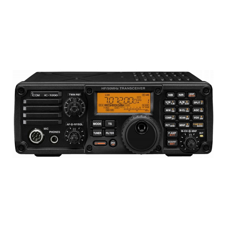
Icom IC-7200 Advanced Instructions
Hide thumbs
Also See for IC-7200:
- Service manual (135 pages) ,
- Instruction manual (104 pages) ,
- Installation manual (20 pages)
Table of Contents
Advertisement
Quick Links
Previous view
About these Advanced Instructions (PDF format)
These Advanced Instructions describe the details of the IC-7200 features. This PDF formatted manual provides you
with convenient functions, as follows.
Move to the previously read page.
Click [Previous view] at the left top on an each page, to
move back to the previously read page.
Shows the location of keys
When the cursor is moved over a term with a red un-
derline, a red circle appears around the appropriate
key(s) on the figure of the transceiver.
Example: When the cursor is moved over
description, a red circle appears around the
appropriate key(s).
Shows a term description
When the mouse cursor is moved over a term which
is highlighted in yellow, the description of the term is
displayed.
Icom, Icom Inc. and the Icom logo are registered trademarks of Icom Incorporated (Japan) in Japan, the United States, the
United Kingdom, Germany, France, Spain, Russia and/or other countries.
Adobe and Adobe Reader are registered trademark of Adobe Systems Incorporated.
All other products or brands are registered trademarks or trademarks of their respective holders.
INTRODUCTION
The screen shots at the right column, correspond to
the operating instructions and procedures shows both
setting and operating example.
Previous view
3
BASIC OPERATION
Frequency setting (Continued)
�
D Quick tuning function
The operating frequency can be changed in steps of
0.1, 1, 5, 9 or 10 kHz selectable for quick tuning.
Push
q
•
"Z
" appears.
Rotate
w
grammed kHz steps.
e
Push
tion.
•
"Z" disappears.
Rotate
r
in the
TS
D Selecting 'kHz' step
When the Quick tuning function is selected, the fre-
quency can be changed in the selected 'kHz' steps.
• 0.1, 1, 5, 9 or 10 kHz are selectable.
q
Push
•
"Z" appears.
w
Hold down
step Set mode.
e
Rotate
0.1, 1, 5, 9 or 10 kHz.
Push
r
Rotate
t
to the set tuning step.
Push
y
•
"Z" disappears.
TS
to turn ON the Quick tuning function.
[DIAL] to change the frequency in pro-
TS
again to turn OFF the Quick tuning func-
[DIAL] for normal tuning, if desired.
TS
to turn ON the Quick tuning function.
TS
for 1 second to enter the tuning
[DIAL] to select the desired tuning step of
to exit the tuning step Set mode.
TS
Tuning step Set mode
[DIAL] to change the frequency according
to turn OFF the Quick tuning function.
TS
3-7
Appears
[DIAL]
Appears
Hold down
TS
[DIAL]
Advertisement
Chapters
Table of Contents

Subscribe to Our Youtube Channel
Related Manuals for Icom IC-7200


Summary of Contents for Icom IC-7200
- Page 1 [DIAL] Icom, Icom Inc. and the Icom logo are registered trademarks of Icom Incorporated (Japan) in Japan, the United States, the United Kingdom, Germany, France, Spain, Russia and/or other countries. Adobe and Adobe Reader are registered trademark of Adobe Systems Incorporated.
-
Page 2: Functions And Features
Previous view INTRODUCTION ® ® Functions and features of Adobe Reader The following functions and features can be used with Adobe ® Reader ® • Keyword search Click “Find (Ctrl+F)” or “Advanced • Find screen Search (Shift+Ctrl+F)” in the Edit menu to open the search screen. - Page 3 ADVANCED INSTRUCTIONS INTRODUCTION HF/50 MHz TRANSCEIVER PANEL DESCRIPTION Iç-7200 INSTALLATION AND CONNECTIONS BASIC OPERATION RECEIVE AND TRANSMIT FUNCTIONS FOR RECEIVE FUNCTIONS FOR TRANSMIT MEMORY OPERATION SCAN OPERATION ANTENNA TUNER OPERATION 10 SET MODE 11 CONTROL COMMAND 12 INFORMATION INDEX INDEX...
-
Page 4: Table Of Contents
PANEL DESCRIPTION Section Front panel ..............1-2 ■ Keypad ............... 1-9 Function display ............1-12 ■ Rear panel ..............1-14 ■ ACC socket information ........... 1-16 Microphones ..............1-17 ■ SM-50 (Option) ............1-17 SM-30 (Option) ............1-17 HM-36 ..............1-17... -
Page 5: Panel Description
Previous view PANEL DESCRIPTION ■ Front panel Function Speaker Display (p. 1-12) i7200 METER SPLIT M-CL COMP SCAN MODE F-INP GENE BAND TUNER FILTER P.AMP M-CH/RIT SPCH w NOISE BLANKER KEY (p. 5-7) q PASSBAND TUNING CONTROLS [TWIN PBT] Push to turn the noise blanker function ON or Adjust the receiver’s DSP filter passband width. -
Page 6: Keypad
Previous view PANEL DESCRIPTION Front panel (Continued) ■ Function Speaker Display (p. 1-12) i7200 METER SPLIT M-CL COMP SCAN MODE F-INP GENE BAND TUNER FILTER P.AMP M-CH/RIT SPCH t KEYPAD r ANF/METER KEY (p. 5-9) METER Push the keys to select various functions. Details ➥... - Page 7 Previous view PANEL DESCRIPTION Front panel (Continued) ■ Function Speaker Display (p. 1-12) i7200 METER SPLIT M-CL COMP SCAN MODE F-INP GENE BAND TUNER FILTER P.AMP M-CH/RIT SPCH u M-CH/RIT CONTROL [M-CH] (inner control) While in the Set mode/Quick Set mode, rotate to What is the RIT function? ➥...
- Page 8 Previous view PANEL DESCRIPTION Front panel (Continued) ■ Function Speaker Display (p. 1-12) i7200 METER SPLIT M-CL COMP SCAN MODE F-INP GENE BAND TUNER FILTER P.AMP M-CH/RIT SPCH o MANUAL NOTCH FILTER CONTROL [MNF] !0 TUNING STEP KEY (pp. 3-7, 3-8) (outer control;...
- Page 9 Previous view PANEL DESCRIPTION Front panel (Continued) ■ Function Speaker Display (p. 1-12) i7200 METER SPLIT M-CL COMP SCAN MODE F-INP GENE BAND TUNER FILTER P.AMP M-CH/RIT SPCH !5 !4 SPCH P.AMP !2 PREAMP/ATTENUATOR KEY (p. 5-3) !5 SPCH•LOCK KEY Push to turn the preamp ON or OFF.
- Page 10 Previous view PANEL DESCRIPTION Front panel (Continued) ■ Function Speaker Display (p. 1-12) i7200 METER SPLIT M-CL COMP SCAN MODE F-INP GENE BAND TUNER FILTER P.AMP M-CH/RIT SPCH !8 RF GAIN/SQUELCH CONTROL [RF/SQL] • When functioning as the RF GAIN/SQL control (outer control: p.
- Page 11 Previous view PANEL DESCRIPTION Front panel (Continued) ■ Function Speaker Display (p. 1-12) i7200 METER SPLIT M-CL COMP SCAN MODE F-INP GENE BAND TUNER FILTER P.AMP M-CH/RIT SPCH !9 AF CONTROL [AF] (inner control; p. 3-11) Adjusts the audio output level from the speaker. Audio output increases Audio output...
-
Page 12: D Keypad
Previous view PANEL DESCRIPTION D Keypad METER SPLIT SPLIT M-CL M-CL COMP SCAN F-INP COMP SCAN GENE BAND P.AMP F-INP ENT GENE BAND M-CH/RIT SPCH @2 VFO/MEMORY/1/1.8 MHz BAND KEY @4 SPLIT/3/7 MHz BAND KEY SPLIT Push to toggle the operating mode between the (p. - Page 13 Previous view PANEL DESCRIPTION Keypad (Continued) METER SPLIT SPLIT M-CL M-CL COMP SCAN F-INP COMP SCAN GENE BAND P.AMP F-INP ENT GENE BAND M-CH/RIT SPCH @6 MEMORY CLEAR/5/14 MHz BAND KEY @8 SPEECH COMPRESSOR/7/21 MHz BAND KEY M-CL COMP Hold down for 1 second to clear the displayed Push to turn the Speech compressor function ➥...
- Page 14 Previous view PANEL DESCRIPTION Keypad (Continued) METER SPLIT SPLIT M-CL M-CL COMP SCAN F-INP COMP SCAN GENE BAND P.AMP F-INP ENT GENE BAND M-CH/RIT SPCH #0 VOX/9/28 MHz BAND KEY #2 RIT/•/GENERAL BAND KEY Push to turn the VOX function ON or OFF. Push to turn the RIT (Receiver Incremental Tun- ➥...
-
Page 15: Function Display
Previous view PANEL DESCRIPTION ■ Function display q TRANSMIT ICON i S/RF METER Appears while transmitting. Displays the receiving signal strength. ➥ Displays either the transmit power (PO), SWR or ➥ w MODE ICONS ALC while transmitting. (p. 3-13) Shows the selected operating mode. o NOTCH ICONS (p. - Page 16 Previous view PANEL DESCRIPTION Function display (Continued) ■ !5 QUICK TUNING STEP ICON Appears when the Quick tuning function is selected. (p. 3-7, 3-8) !6 RIT ICON (p. 5-2) Appears when the RIT function is ON. !7 VFO ICONS (p. 3-2) “VFO A”...
-
Page 17: Rear Panel
Previous view PANEL DESCRIPTION ■ Rear panel REMOTE E X T SP SEND TUNER DC 13.8V q TUNER CONTROL SOCKET [TUNER] (p. 2-6) t ELECTRONIC KEYER JACK [KEY] Accepts the control cable from an optional antenna Accepts a key or paddle connector for the internal tuner. - Page 18 PC. u ALC INPUT JACK [ALC] (p. 2-7) CAUTION: Connects to the ALC output jack of a non-Icom lin- The USB driver must be installed. Please read ear amplifier. the USB driver installation guide before installing the USB driver into your PC that is connected to i ANTENNA CONNECTOR [ANT] (p.
-
Page 19: Dacc Socket Information
To prevent this, we recommend adding a switching diode, such as an “1SS133,” on the load side of the circuit to the counter-electromotive force absorption. When the diode is added, a switching delay of the relay may occur. Be sure to check its switching action before operation. [Example] Switching diode To a non-Icom socket linear amplifier eSEND Relay i13.8V... -
Page 20: Microphones
Previous view PANEL DESCRIPTION ■ Microphones D SM-50 (Option) q PTT SWITCH Hold down to transmit; release to receive. w PTT LOCK SWITCH (Only for the SM-50 and SM-30) Push to lock the PTT switch in the transmit mode. e UP/DOWN SWITCHES [UP]/[DN] Change the selected readout frequency or memory channel. - Page 21 PTT CAUTION: DO NOT short pin 2 to ground as this r Squelch switch can damage the internal 8 V regulator. DC voltage is applied to pin 1 for microphone operation. Use caution when using a non-Icom microphone. 1-18...
- Page 22 INSTALLATION AND CONNECTIONS Section Unpacking ..............2-2 ■ Selecting a location ............2-2 ■ Grounding ..............2-2 ■ Connecting an antenna ..........2-2 ■ Basic connections ............2-3 ■ Optional connections ............. 2-4 ■ Power supply connections ..........2-5 ■ Connecting the DC Power Supply .........
-
Page 23: Installation And Connections
For best results, connect a copper or copper-plated tenna tuner. The IC-7200 has an SWR meter to con- ground rod driven into the earth. Make the distance tinuously monitor the antenna SWR. -
Page 24: Basic Connections
Previous view INSTALLATION AND CONNECTIONS ■ Basic connections • Front panel Microphones (p. 1-17) i7200 Optional SM-50 Optional HM-36 SM-30 • Rear panel DC POWER SUPPLY (p. 2-5) HF/50 MHz ANTENNA PS-126 (p. 2-2) GROUND Use the heaviest gauge wire CW KEY or strap available and make the connection as short and... -
Page 25: Optional Connections
• Rear panel REMOTE (p. 11-2) Used for computer control and transceive operation. with AH-4 (p. 2-6) AH-2b or long wire EXTERNAL SPEAKER SP-34 (option) ACC SOCKET (p. 1-16) [SEND], [ALC] (p. 2-7) Used to connect to a non-Icom linear amplifier. -
Page 26: Power Supply Connections
DC power cable because the connector is tightly locked. Use a small tool, such as a flat-bladed screwdriver, to disengage the locking tab. CONNECTING A NON-ICOM DC POWER SUPPLY AC outlet A DC power supply Transceiver 13.8 V; at least 22 A... -
Page 27: Battery Connections
AT-180 Either of the two AT-180 [ANT] [ANT] [ACC] external connectors [ACC] IC-7200 Ground [TRANSCEIVER] Ground • Turn the IC-7200’s power OFF when connecting the AT-180, otherwise, the CPU may malfunction and the AT-180 may not function properly. -
Page 28: Connecting A Linear Amplifier
: 230 V CONNECTING A NON-ICOM LINEAR AMPLIFIER R WARNING: The IC-7200 SEND line is rated at 16 V/200 mA DC. If this level is exceeded, a larger external relay • Set the transceiver output power and linear am- must be used. -
Page 29: Connecting A Cw Keyer
Previous view INSTALLATION AND CONNECTIONS ■ Connecting a CW keyer Set mode settings (p. 10-15) Rear panel N o rm al Paddle polarity: Normal R evers e Paddle polarity: Reverse For no break-in operation: Paddle Connect an external switch B u g 9 10 11 such as a foot switch;... -
Page 30: Connecting A Pc/Tnc For Rtty
Previous view [EXT SP] INSTALLATION AND CONNECTIONS 2-conductor ⁄ " plug ■ Connecting a PC/TNC for RTTY D Connections for RTTY (FSK) Rear panel [ACC] TNC or PC interface SQL* (light green) for the RTTY software FSKK (black) 9 10 11 AF out (light blue) Colors refer to the wires in SEND (orange) -
Page 31: Connecting A Pc/Tnc For Sstv Or Psk31
Connect SQL line when required. D Connecting to the [USB] jack Connect an USB cable (third party’s) between the transceiver’s USB jack and PC. (p. 1-15) The USB driver and the installation guide can be down- loaded from our website. http://www.icom.co.jp/world/ ➥ 2-10... -
Page 32: Basic Operation
BASIC OPERATION Section Understanding the VFO ..........3-2 ■ VFO operation ............... 3-2 ■ Selecting the VFO A or B ........... 3-2 Equalizing the VFOs ..........3-2 Selecting the VFO and memory modes ......3-3 ■ Understanding the VFO mode and the memory modes ............ -
Page 33: Understanding The Vfo
(p. 3-4) The IC-7200 has two VFOs, VFO A and VFO B, espe- cially suited for split frequency operation. You can use the desired VFO to select a frequency and operating mode. -
Page 34: Selecting The Vfo And Memory Modes
Previous view BASIC OPERATION ■ Selecting the VFO and memory modes Push to toggle between the VFO and the ➥ memory modes. D Understanding the VFO mode and the memory modes VFO MODE [EXAMPLE] Each VFO display shows a frequency and operat- VFO is selected. -
Page 35: Selecting An Operating Band
Previous view BASIC OPERATION ■ Selecting an operating band The transceiver has a band stacking register. This Band keys function automatically memorizes the last operating frequency and mode used on a particular band. This is convenient for contest operation. See the table below for a list of the bands available and the default settings for each register. -
Page 36: Setting The Operating Frequency
Previous view BASIC OPERATION ■ Setting the operating frequency The transceiver has several tuning methods for convenient frequency tuning. D Using the main dial F-INP ENT q After holding down for 1 second, push the BAND desired band key to select the corresponding band. •... -
Page 37: D Entering A Frequency From The Keypad
Previous view BASIC OPERATION Frequency setting (Continued) ■ D Entering a frequency from the keypad The transceiver has a keypad for direct frequency en- try, as described below. Keypad F-INP ENT Push BAND Input the desired frequency with the numeric keys on the keypad. -
Page 38: D Quick Tuning Function
Previous view BASIC OPERATION Frequency setting (Continued) ■ D Quick tuning function The operating frequency can be changed in steps of 0.1, 1, 5, 9 or 10 kHz selectable for quick tuning. Appears Push to turn ON the Quick tuning function. •... -
Page 39: D Selecting The 1 Hz And 10 Hz Tuning Steps
Previous view BASIC OPERATION Frequency setting (Continued) ■ D Selecting the 1 Hz and 10 Hz tuning steps 10 Hz tuning When the Quick tuning step icon, “Z,” disappears, ro- tating [DIAL] changes the frequency in increments of 1 or 10 Hz. NOTE: The frequency is changed in 50 Hz steps when the [UP]/[DN] switches of the microphone Rotating [DIAL] changes the... -
Page 40: D Selecting The Auto Tuning Step
Previous view BASIC OPERATION Frequency setting (Continued) ■ D Selecting the Auto tuning step When rotating the tuning dial rapidly, the tuning speed accelerates automatically if selected. M-CH/RIT Hold down for 1 second twice to enter the Set mode. Rotate [M-CH] to select “AUTo TS.”... -
Page 41: D Setting The Band Edge Warning Beep
Previous view BASIC OPERATION Frequency setting (Continued) ■ D Setting the Band edge warning beep When selecting a frequency that is outside of a band’s specified frequency range, a warning beep sounds. The beep function can be turned OFF in the Set mode, if desired. -
Page 42: Selecting The Operating Mode
Previous view BASIC OPERATION ■ Selecting the operating mode The following modes are selectable in the IC-7200: OPERATING MODE SELECTION SSB (USB/LSB), SSB data (USB data/LSB data), CW, CW-R (CW Reverse), RTTY, RTTY-R (RTTY Re- verse), AM and AM data modes. -
Page 43: Locking The Dial
Previous view BASIC OPERATION ■ Locking the Dial The dial lock function prevents accidental changes by [DIAL] being rotated. Appears SPCH ➥ Hold down for 1 second to turn the dial lock function ON or OFF. • “ ” appears when the dial lock function is ON. ■... -
Page 44: Selecting The Meter Function
MIC gain setting (see page 3-14) in the Quick Set mode. ■ Using the Voice synthesizer function The IC-7200 has a voice synthesizer. This function announces the S-meter level, operating frequency and mode in a clear, electronically generated voice, in English or Japanese. -
Page 45: Basic Transmit Operation
Previous view BASIC OPERATION ■ Basic transmit operation Before transmitting, monitor your selected oper- It’s good Amateur practice to listen first. On the ating frequency to make sure transmitting won’t HF bands, even if nothing is heard, ask “is the fre- cause interference to other stations on the same quency in use”... -
Page 46: Receive And Transmit
RECEIVE AND TRANSMIT Section Operating in the SSB mode ........... 4-2 ■ Convenient functions for receiving ......4-2 Convenient functions for transmit ....... 4-4 Operating in the CW mode ..........4-5 ■ Convenient functions for receiving ......4-6 Convenient functions for transmit ....... -
Page 47: Operating In The Ssb Mode
Previous view RECEIVE AND TRANSMIT ■ Operating in the SSB mode F-INP ENT Hold down for 1 second, then push a BAND band key to select the desired band. Band keys Push to select the SSB mode. MODE • Hold down for 1 second to toggle between the MODE LSB and USB modes. - Page 48 Previous view RECEIVE AND TRANSMIT ■ Operating in the SSB mode Convenient functions for receiving (Continued) • AGC (auto gain control) (p. 5-3) Push once or twice to set the AGC time con- ➥ stant to fast or slow. • “F.AGC” appears when the fast time constant is select- ed, and no icon appears when the slow time constant is selected.
-
Page 49: D Convenient Functions For Transmit
Previous view RECEIVE AND TRANSMIT ■ Operating in the SSB mode (Continued) D Convenient functions for transmit • VOX (voice operated transmit) (p. 6-2) Push to turn the VOX function ON or OFF. ➥ • “ ” appears when the VOX function is ON. Hold down for 1 second to enter the VOX Set ➥... -
Page 50: Operating In The Cw Mode
Previous view RECEIVE AND TRANSMIT ■ Operating in the CW mode Connect a paddle, straight key or external electron- ic keyer as described on page 2-8. “CW” or “CW-R” appears. Hold down F-INP ENT for 1 second, then push a BAND band key to select the desired band. -
Page 51: D Convenient Functions For Receiving
Previous view RECEIVE AND TRANSMIT Operating in the CW mode (Continued) ■ D Convenient functions for receiving • Preamp and attenuator (p. 5-3) P.AMP Push to turn the preamp ON or OFF. ➥ • “ ” appears when the preamp is ON. P.AMP Hold down for 1 second to turn ON the at-... -
Page 52: D Convenient Functions For Transmit
Previous view RECEIVE AND TRANSMIT Operating in the CW mode ■ Convenient functions for receiving (Continued) • Manual notch filter (p. 5-10) Push to turn the manual notch filter ON or ➥ OFF. • “ ” appears when the manual notch filter is ON. Hold down for 1 second to enter the manual ➥... -
Page 53: D Selecting The Cw-R (Cw Reverse) Mode
Previous view RECEIVE AND TRANSMIT Operating in the CW mode (Continued) ■ D Selecting the CW-R (CW reverse) mode The CW-R (CW Reverse) mode receives CW signals on the reverse sideband like that of the LSB and USB modes. Use when interference is near the desired signal and when you want to shift the tone of the interfering sig- nal. -
Page 54: D Adjusting The Cw Side Tone
Previous view RECEIVE AND TRANSMIT Operating in the CW mode (Continued) ■ D Adjusting the CW side tone When the transceiver is in receive, and the break-in function is OFF, you can listen to the tone of your CW signal without actually transmitting. (pp. 6-4, 6-5) You can also use the CW sidetone to practice CW sending, but be sure to turn OFF the Break-in func- tion. -
Page 55: Operating In The Rtty (Fsk) Mode
Previous view RECEIVE AND TRANSMIT ■ Operating in the RTTY (FSK) mode When using your PC, RTTY terminal or TNC, consult Band keys the manual that comes with the equipment. F-INP ENT Hold down for 1 second, then push a BAND band key to select the desired band. - Page 56 Previous view RECEIVE AND TRANSMIT Operating in the RTTY (FSK) mode ■ Convenient functions for receiving (Continued) • AGC (auto gain control) (p. 5-3) Push once or twice to set the AGC time con- ➥ stant to fast or slow. •...
-
Page 57: D Selecting The Rtty-R (Rtty Reverse) Mode
Previous view RECEIVE AND TRANSMIT Operating in the RTTY (FSK) mode (Continued) ■ D Selecting the RTTY-R (RTTY reverse) mode Received characters are occasionally garbled when the receive signal’s MARK and SPACE are reversed. This reversal can be caused by incorrect TNC con- nections, settings, commands, and so on. -
Page 58: Drtty Decode Set Mode
Previous view RECEIVE AND TRANSMIT Operating in the RTTY (FSK) mode (Continued) ■ D RTTY decode Set mode Set the RTTY key polarity, shift width and mark tone. q When RTTY (RTTY-R) mode is selected, hold down M-CH/RIT for 1 second to enter the Quick Set mode. [M-CH] to select the desired set item. -
Page 59: Operating In The Am Mode
Previous view RECEIVE AND TRANSMIT ■ Operating in the AM mode Band keys F-INP ENT Hold down for 1 second, then push a BAND band key to select the desired band. Push to select AM mode. MODE [DIAL] to tune in a desired signal. Rotate •... -
Page 60: D Convenient Functions For Transmit
Previous view RECEIVE AND TRANSMIT Operating in the AM mode ■ Convenient functions for receiving (Continued) [DIAL] • Noise blanker (p. 5-7) Push to turn the noise blanker ON or OFF. ➥ • “ ” appears when the noise blanker is ON. Hold down for 1 second to enter the noise ➥... -
Page 61: Operating In The Data Mode (Sstv/Psk31)
Previous view RECEIVE AND TRANSMIT ■ Operating in the Data mode (SSTV/PSK31) When operating SSTV or PSK31 with your PC, refer to the software manual. Connect your PC to the transceiver. (p. 2-10) F-INP ENT Hold down for 1 second, then push a BAND band key to select the desired band. -
Page 62: Functions For Receive
FUNCTIONS FOR RECEIVE Section Using the RIT function ........... 5-2 ■ Selecting the preamp and attenuator ......5-3 ■ AGC function ..............5-3 ■ AGC time constant selection ........5-3 Adjusting the Twin PBT operation ........5-4 ■ Selecting the IF filter ............. -
Page 63: Using The Rit Function
Previous view FUNCTIONS FOR RECEIVE ■ Using the RIT function The RIT (Receive Incremental Tuning) function com- pensates for stations transmitting off-frequency, or when you prefer to listen to slightly different sounding voice characteristics. The RIT shifts the receive frequency up to ±9.999 kHz in 1 Hz steps (10 Hz steps when cancelling the 1 Hz step readout) without shifting the transmit frequency. -
Page 64: Selecting The Preamp And Attenuator
Previous view FUNCTIONS FOR RECEIVE ■ Selecting the preamp and attenuator The preamp amplifies received signals in the receiver Either “ ” or input (front end) circuit to improve the S/N ratio and “ ” appears. sensitivity. Turn this function ON when receiving weak signals. -
Page 65: Adjusting The Twin Pbt Operation
Previous view FUNCTIONS FOR RECEIVE ■ Adjusting the Twin PBT operation The Twin PBT (Passband Tuning) function electroni- cally narrows the IF passband width by shifting the IF frequency slightly outside of the IF filter passband to reject interference. This transceiver uses the DSP cir- cuit for the PBT function. -
Page 66: Selecting The If Filter
Previous view FUNCTIONS FOR RECEIVE ■ Selecting the IF filter The transceiver has 3 passband IF filter widths for each mode. For the SSB and CW modes, set the passband width to between 50 and 3600 Hz, in 50 or 100 Hz steps. A total of 41 passband widths can be set. -
Page 67: D Setting The Passband Filter Width
Previous view FUNCTIONS FOR RECEIVE IF filter selection (Continued) ■ D Setting the passband filter width Push several times to select the desired MODE operating mode. Hold down for 1 second to enter filter Set FILTER mode. [M-CH] to select “FIL.” Rotate Push several times to select the desired... -
Page 68: Activating The Noise Blanker
Previous view FUNCTIONS FOR RECEIVE ■ Activating the Noise blanker The noise blanker eliminates pulse-type noise such as from car ignition systems. Push to turn the noise blanker ON or OFF. ➥ • “ ” appears when the NB function is ON. When using the noise blanker, received signals may be distorted if they are excessively strong, or the noise type is other than a pulse type. -
Page 69: Activating The Noise Reduction Function
Previous view FUNCTIONS FOR RECEIVE ■ Activating the Noise reduction function The Noise reduction function enhances desired sig- nals in the presence of noise by using the DSP circuit to remove random noise. The amount of enhance- ment is adjustable. Push to turn the noise reduction ON or OFF. -
Page 70: Activating The Notch Filters
Previous view FUNCTIONS FOR RECEIVE ■ Activating the Notch filters This transceiver has auto and manual notch filter functions. The auto notch filter automatically attenuates beat tones, tuning signals, changing frequency, and so on, even if they are shifting. The manual notch filter can be set to attenuate a fre- quency by rotating the [MNF] control. -
Page 71: D Manual Notch Filter
Previous view FUNCTIONS FOR RECEIVE Notch function (Continued) ■ D Manual notch filter Push to turn the manual notch filter ON or ➥ OFF. • “ ” appears when the manual notch filter is ON. • Rotate the [MNF] control to manually select an interfer- ing signal to attenuate. -
Page 72: Functions For Transmit
FUNCTIONS FOR TRANSMIT Section VOX function ..............6-2 ■ VOX Set mode ............6-3 Break-in function ............6-4 ■ Semi break-in operation ..........6-4 Full break-in operation ..........6-5 Speech compressor ............6-6 ■ Setting the compression level ........6-7 Split frequency operation .......... -
Page 73: Vox Function
Previous view FUNCTIONS FOR TRANSMIT ■ VOX function The VOX (Voice-Operated Transmission) function uses your voice to switch between transmit and re- ceive. This function provides for hands-free operation or to input log entries into your computer, and so on, Appears when the USB while operating. -
Page 74: Dvox Set Mode
Previous view FUNCTIONS FOR TRANSMIT VOX function (Continued) ■ D VOX Set mode Hold down for 1 second to enter the VOX Set mode. [M-CH] to select “VoX GAIN.” Rotate While speaking into the microphone at your normal voice level, rotate [DIAL] to the point where the transceiver continuously transmits. -
Page 75: Break-In Function
■ Break-in function The break-in function is used in the CW mode to auto- matically switch the transceiver between transmit and receive when keying. The IC-7200 is capable of full break-in or semi break-in. Break-in operation is also referred to as QSK. -
Page 76: D Full Break-In Operation
Previous view FUNCTIONS FOR TRANSMIT Break-in function (Continued) ■ D Full break-in operation In full break-in, the transceiver automatically switches to receive between keying dots and dashes so that Appears the operator can hear activity on the frequency. Push to select the CW or CW-R mode. MODE •... -
Page 77: Speech Compressor
Previous view FUNCTIONS FOR TRANSMIT ■ Speech compressor The IC-7200 has a built-in, low distortion speech compressor circuit. This circuit increases your aver- age talk power in the SSB mode, and is especially useful for DX-ing or noisy conditions when the receiv- Appears when the USB ing station is having difficulty copying your signal. -
Page 78: D Setting The Compression Level
Previous view FUNCTIONS FOR TRANSMIT Speech compressor ■ D Setting the compression level • Setting the microphone gain MODE Push to select SSB mode. • Hold down for 1 second to toggle between the MODE USB and LSB modes. Push to turn OFF the speech compressor COMP function, if it is ON. -
Page 79: Split Frequency Operation
Previous view FUNCTIONS FOR TRANSMIT ■ Split frequency operation Split frequency operation allows you to transmit and receive in the same mode on two different frequen- cies, in the same band. The split frequency operation uses both VFO A and VFO B. The transmit and receive frequencies must be in the same band Example: Setting 7.0620 MHz for receiving and... - Page 80 Previous view FUNCTIONS FOR TRANSMIT Split frequency operation (Continued) ■ CONVENIENT! ❍ QUICK SPLIT FUNCTION (p. 6-10) SPLIT When you hold down for 1 second, the split SPLIT function is set to ON, and the band, frequency and mode of the undisplayed VFO is set the same as those of the displayed VFO.
-
Page 81: D Using The Quick Split Function
Previous view FUNCTIONS FOR TRANSMIT Split frequency operation (Continued) ■ D Using the Quick split function When you find a DX station that is operating Split, an important consideration is how to set the split fre- quency. When you hold down for 1 second, the split SPLIT function is set to ON, and the band, frequency and... -
Page 82: Split Lock Function
*XFC function should be turned ON first. (p. 10-11) [M-CH] [DIAL] ■ Measuring SWR The IC-7200 has a built-in circuit for measuring an- tenna SWR—no external equipment is necessary. Push one or more times to select the RTTY MODE mode. -
Page 83: Memory Operation
MEMORY OPERATION Section About the Memory channels .......... 7-2 ■ Selecting Memory channels .......... 7-2 ■ Programming memory channels ........7-3 ■ Programming in VFO mode ........7-3 Programming in memory mode ......... 7-4 Copying a frequency ............7-5 ■ Copying in the memory mode ........ -
Page 84: About The Memory Channels
Previous view MEMORY OPERATION ■ About the Memory channels The transceiver has 201 memory channels, including 2 scan edge channels. The Memory mode is very useful to quickly select of- ten-used frequencies. All 201 memory channels are tuneable, which means the programmed frequency can be tuned temporarily by rotating [DIAL], even in the memory mode. -
Page 85: Programming Memory Channels
Previous view MEMORY OPERATION ■ Programming memory channels You can program the Memory channels in either the VFO mode or in the Memory mode. D Programming in VFO mode [EXAMPLE]: Programming 7.088 MHz/LSB Push to select the VFO mode. into channel 12. [EXAMPLE]: Programming 7.088 MHz/LSB [DIAL] to set the desired frequency, and Rotate... -
Page 86: D Programming In Memory Mode
Previous view MEMORY OPERATION Memory programming (Continued) ■ D Programming in memory mode Push to select the Memory mode. [EXAMPLE]: Programming 21.280 MHz/USB [M-CH] to select the desired memory chan- Rotate [EXAMPLE]: Programming 21.280 MHz/USB into channel 18. nel. into channel 18. Memory mode M-CH/RIT •... -
Page 87: Copying A Frequency
Previous view MEMORY OPERATION ■ Copying a frequency You can copy the frequency and operating mode in a memory channel to the VFO. D Copying in the memory mode This is useful for copying a memory channel’s con- tents (frequency and operating mode) to a VFO while in the Memory mode. -
Page 88: Clearing A Memory
Previous view [EXAMPLE]: Copying the contents of memory 16. MEMORY OPERATION Operating frequency : 14.020 MHz/CW Contents of memory 16 : 14.018 MHz/CW Memory mode ■ Clearing a memory Any memory channels can be cleared. The cleared memory channels become blank channels. Push to select the Memory mode. -
Page 89: Scan Operation
SCAN OPERATION Section Scan types ..............8-2 ■ Preparation ..............8-2 ■ Scan edges programming ..........8-3 ■ Scanning between programmed channels (VFO mode) .. 8-4 ■ Scanning Memory channels (Memory mode) ....8-5 ■... -
Page 90: Scan Types
SCAN OPERATION ■ Scan types Scanning automatically searches for signals and makes it easier to locate new stations for contact or listening purposes. The IC-7200 has two scan types; Programmed scan and Memory scan. PROGRAMMED SCAN MEMORY SCAN Repeatedly scans between two scan edge frequencies Repeatedly scans all programmed memory channels that (scan edge memory channels P1 and P2). -
Page 91: Scan Edges Programming
Previous view SCAN OPERATION ■ Scan edges programming Memory channels P1 and P2 are the Program Scan Edge channels. They are used to program the upper and lower frequency edges for the programmed scan. (p. 8-4) Factory default frequency and operating modes are programmed into the Scan Edge channels. - Page 92 Previous view SCAN OPERATION ■ Scanning between programmed channels (VFO mode) A programmed scan searches for signals between scan edge memory channels P1 and P2. The default frequencies for these memories are 0.500000 MHz and 29.99999 MHz. See page 8-3 for scan edges programming. Push to select the VFO mode.
- Page 93 Previous view SCAN OPERATION ■ Scanning Memory channels (Memory mode) A Memory scan searches for signals through memory channels 1 to 199. Blank (unprogrammed) memory channels are skipped. Push to select the Memory mode. Close the squelch with the [RF/SQL] control. Push to start the scan.
-
Page 94: Antenna Tuner Operation
ANTENNA TUNER OPERATION Section About the optional AT-180 ... 9-2 ■ automatic antenna tuner Automatic tuning ............9-2 Manual tuning ............9-2 Setting the AT-180 internal switches ......9-3 ■ About the optional AH-4 ..9-4 ■ automatic antenna tuner Operating the AH-4 ............ -
Page 95: Set Mode
The AT-180 automatic antenna tuner automatically CAUTION: NEVER transmit with the tuner ON if no matches the IC-7200 to your antenna. Once the tuner antenna is connected. This will damage both the matches the antenna, the variable capacitor settings transceiver and antenna tuner. - Page 96 Previous view ANTENNA TUNER OPERATION ■ Setting the AT-180 internal switches The optional AT-180 has 3 operating configurations for HF band operation. Select a suitable configura- tions for your antenna system. q Remove the top cover of the AT-180. • AT-180 inside top cover w Set the tuner switches to the desired positions ac- cording to the table below.
- Page 97 ANTENNA TUNER OPERATION ■ About the optional AH-4 automatic antenna tuner The AH-4 matches the IC-7200 to a long wire antenna R DANGER HIGH VOLTAGE! more than 7 m/23 ft long (3.5 MHz and above). NEVER touch the antenna element while tuning or •...
- Page 98 SET MODE Section About the Set Mode ............. 10-2 ■ Using the Quick Set mode ........10-2 Using the Set mode ..........10-3 Items in the Quick Set mode ........10-4 ■ Items in the Set mode ..........10-7 ■ Connect a paddle to the [MIC] connector ....
-
Page 99: Set Mode
Previous view SET MODE ■ About the Set Mode The Set mode is for programming infrequently changed values or functions. The IC-7200 has 2 separate Set modes: the Quick Set mode and the Set mode. Normal operation mode Push Hold down... -
Page 100: D Using The Set Mode
Previous view SET MODE D Using the Set mode M-CH/RIT Hold down for 1 second to enter the Quick Set mode. M-CH/RIT Hold down for 1 second again to enter the Set mode. Rotate [M-CH] to select the desired item. Normal operation mode [DIAL]. -
Page 101: Items In The Quick Set Mode
Previous view SET MODE ■ Items in the Quick Set mode Range or Value Operating Descriptions Item Refer (Default is shown in bold) Mode L (Low) and 1 to 100%, in 1% steps Adjusts the RF output power. RF POWER p. - Page 102 Previous view SET MODE Items in the Quick Set mode (Continued) ■ Data mode (SSB/AM modes) Turn the data mode ON or OFF. When the data mode is turned ON, the audio, input from the [ACC] connector, the [MIC] connector, or the [USB] connector, is used depending on the selection in the Set Mode.
- Page 103 Previous view SET MODE Items in the Quick Set mode (Continued) ■ Twin peak filter (RTTY mode) Turn the twin peak filter ON or OFF. : The Twin peak filter is ON. : The Twin peak filter is OFF. OFF (default) NOTE: The RTTY mark frequency (2125 Hz) and shift width (170 Hz) are automatically set when the twin peak filter is ON.
-
Page 104: Items In The Set Mode
Previous view SET MODE ■ Items in the Set mode Range or Value Item Descriptions Refer (Default is shown in bold) HI (High), Lo (Low) or oF LCD BACKLIGHT Sets the brightness of the LCD. (Off) BEEP on or oF Turns the Confirmation beep ON or OFF. - Page 105 Previous view SET MODE Items in the Set mode (Continued) ■ Range or Value Item Descriptions Refer (Default is shown in bold) Sets the rate at which frequencies are HI (faster) or Lo (slower) MIC UP/DOWN SPEED scanned when the microphone [UP]/[DN] p.
- Page 106 Previous view SET MODE Items in the Set mode (Continued) ■ LCD Backlight Set the brightness of the LCD to HI (High), Lo (Low) or oF (Off). High (default) Beep A beep sounds each time a key is pushed. This func- tion can be turned OFF for silent operation.
- Page 107 Previous view SET MODE Items in the Set mode (Continued) ■ RF/SQL Control Set as the RF/squelch control, the squelch control only (RF gain is fixed at maximum) or Auto (RF gain control in SSB, CW and RTTY; squelch control in AM).
- Page 108 Previous view SET MODE Items in the Set mode (Continued) ■ Turn the XFC (transmit frequency check) function ON or OFF. : The transmit frequency can be monitored while holding down : The transmit frequency check function is OFF. OFF (default) NOTE: When the XFC function is ON, the RIT cal- culation function is disabled.
- Page 109 Previous view SET MODE Items in the Set mode (Continued) ■ USB Level Sets the input modulation level of the USB jack to between 0% to 100% in 1% steps. 50% (default) Speech Level Adjusts the volume level of the speech function to be- tween 0% and 100%, in 1% steps.
- Page 110 Previous view SET MODE Items in the Set mode (Continued) ■ Scan Speed Sets the speed at which channels or frequencies are scanned during scanning. High and low can be selected. HI : Fast scan Lo : Slow scan High (default) Scan Resume This item turns the scan resume function ON or OFF.
- Page 111 Previous view SET MODE Items in the Set mode (Continued) ■ SSB/CW Synchronous Tuning Turns the displayed frequency shift function ON or OFF. When this function is set to ON, the received signal will remain the same even when the operating mode is changed between SSB and CW.
- Page 112 Previous view SET MODE Items in the Set mode (Continued) ■ Dot/Dash Ratio Sets the internal electronic keyer dot/dash ratio be- tween 1:1:2.8 and 1:1:4.5, in 0.1 unit steps. Keying weight example: Morse code “K” DOT (Fixed*) 1:1:3.0 (default) Weight setting: DASH DASH 1:1:3 (default)
- Page 113 When 2 or more IC-7200s are connected to an op- tional CT-17 CI-V LEVEL CONVERTER, rotate [DIAL] 76h (default) to select a different address for each IC-7200 in the range 01h to 7Fh. 76 : Set address to 76h 10-16...
-
Page 114: D Connect A Paddle To The [Mic] Connector
Icom HF transceivers or receivers through a CT-17. When “ON” is selected, changing the frequency, oper- ating mode, and so on, on the IC-7200, automatically ON (default) changes those of the other transceivers or receivers, and vice versa. -
Page 115: Control Command
CONTROL COMMAND Section Controlling the radio with CI-V ........11-2 ■ CI-V connection example ......... 11-2 Data format .............. 11-2 Command table ............11-3 Band stacking register ..........11-5 Data mode with filter width setting ......11-5 Memory content setting ........... -
Page 116: Controlling The Radio With Ci-V
(CI-V) controls the following func- tions of the transceiver. Up to four Icom CI-V transceivers or receivers can be connected to a personal computer equipped with an ct-17 RS-232C port. See page 10-16, 10-17 to set the CI-V option in the Set mode. -
Page 117: D Command Table
Previous view CONTROL COMMAND Controlling the radio with CI-V (Continued) ■ D Command table Cmd. Sub cmd. Data Description Cmd. Sub cmd. Data Description — — Send frequency data. 0 to 255 Send/read [AF] level setting (for transceive operation) (0=max. CCW to 255=max. CW) 0 to 255 Send/read [RF] level setting —... - Page 118 Previous view CONTROL COMMAND Controlling the radio with CI-V ■ Command table (Continued) Cmd. Sub cmd. Data Description Cmd. Sub cmd. Data Description 0 to 40 Send/read the selected filter width 0323 Send/read MIC selection for MOD input ( SSB, CW, RTTY: 0=50 Hz to connector during DATA OFF 40/31=3600/2700 Hz;...
-
Page 119: D Band Stacking Register
Previous view CONTROL COMMAND Controlling the radio with CI-V ■ Command table (Continued) D Band stacking register Command: 1A 01 Cmd. Sub cmd. Data Description To send or read the desired band stacking register’s 0343 Send/read MIC UP/DOWN keyer (HM- 36) OFF contents, a combination of the frequency band and the Send/read MIC UP/DOWN keyer (HM-... -
Page 120: D Memory Content Setting
Previous view CONTROL COMMAND D Memory content setting Command: 1A 00 q、 w r∼i o、 !0 r∼!1 …… X X X X X X X X ………… q, w Memory channel number o, !0 Operating mode setting 0001–0199 : Memory channel 1 to 199 0200 : Programmed scan edge P1 0201... -
Page 121: Information
INFORMATION Section Band voltage modification ........... 12-2 ■ 12-1... -
Page 122: Band Voltage Modification
(q) is completed, or the regulated 8 V is on pin 1 of [ACC] connector after modification (w) is completed. Performing this modification is the customer’s re- sponsibility. Icom does not guarantee this modifica- Front panel tion’s result. CAUTION: Disconnect the DC power cable from the Bridge these transceiver before working on the transceiver. - Page 123 Previous view INDEX AM mode operation ……………………………… 4-14 CI-V Convenient functions for receiving …………… 4-14 Address ……………………………………… 10-16 Convenient functions for transmit …………… 4-15 Band stacking register ………………………… 11-5 Baud Rate …………………………………… 10-16 Antenna tuner Connection example …………………………… 11-2 AH-4 …………………...
- Page 124 Previous view INDEX Frequency Measuring SWR ………………………………… 6-11 Operating frequency setting …………………… Using the keypad …………………………… Memory mode …………………………………… Using the main dial …………………………… Memory channels ……………………………… 5 MHz band operation (USA version only) …… 3-10 Clearing ………………………………………… Copying ………………………………………… Front panel ………………………………………...
- Page 125 Previous view INDEX Operating band selection ……………………… Scan Using the band stacking register ……………… Memory scan …………………………………… Preparation ……………………………………… Operating frequency setting …………………… Programmed scan ……………………………… 5 MHz band operation (USA version only) …… 3-10 Scan edges programming ……………………… Using the keypad ……………………………… Resume ………………………………………...
- Page 126 Previous view INDEX Transmitting ……………………………………… 3-14 Output power setting …………………… 3-14, 10-4 Microphone gain setting ……………… 3-14, 10-4 Tuning step 1 Hz and 10 Hz tuning steps selection ……… Auto tuning step selection ……………… 3-9, 10-13 ‘kHz’ step selection …………………………… Quick tuning function ……………………………...
- Page 127 A-6668-6EX 1-1-32 Kamiminami, Hirano-ku, Osaka 547-0003, Japan © 2012 Icom Inc.
Need help?
Do you have a question about the IC-7200 and is the answer not in the manual?
Questions and answers