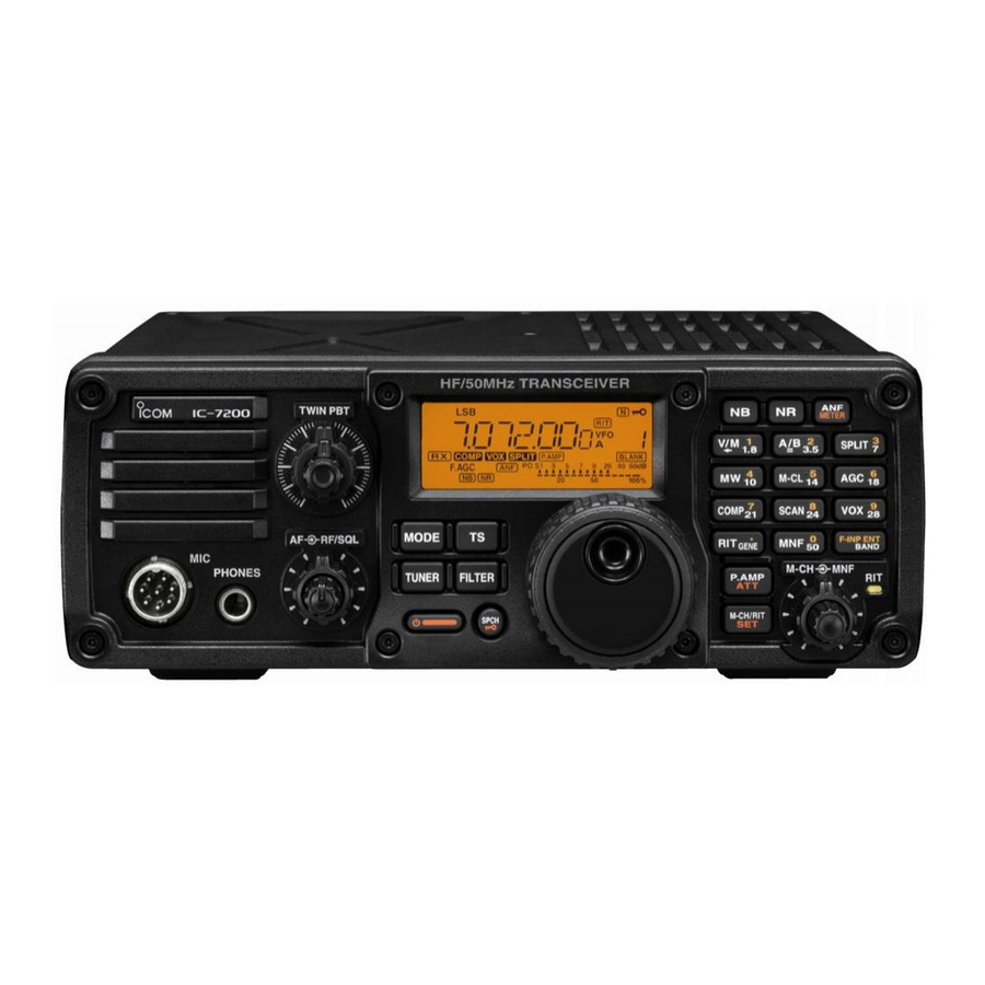
Icom IC-7200 Instruction Manual
Hf/50 mhz transceiver
Hide thumbs
Also See for IC-7200:
- Service manual (135 pages) ,
- Advanced instructions (127 pages) ,
- Instruction manual (104 pages)
Table of Contents
Advertisement
Quick Links
Advertisement
Table of Contents

Related Manuals for Icom IC-7200


Summary of Contents for Icom IC-7200
- Page 1 INSTRUCTION MANUAL HF/50 MHz TRANSCEIVER i7200...
-
Page 2: Foreword
We understand that you have a choice of many differ- ent radios in the market place. We want to thank you for making the IC-7200 your radio of choice, and hope you agree with Icom’s philosophy of “technology first.” Many hours of research and development went into the design of your IC-7200. -
Page 3: Precautions
(such as on a slanted surface or and connection to the IC-7200 may damage the vibrated place). This may cause injury and/or damage transceiver or microphone. to the transceiver. -
Page 4: About The Supplied Cd
PRECAUTIONS (CONTINUED) During mobile operation, NEVER place the transceiver where air bag deployment may be obstructed. During mobile operation, DO NOT place the transceiv- er where hot or cold air blows directly onto it. During mobile operation, DO NOT operate the transceiv- er without running the vehicle’s engine. -
Page 5: Table Of Contents
TABLE OF CONTENTS IMPORTANT ............... i 4 MEMORY OPERATION ........ 21–22 ■ About the Memory channels ......21 FOREWORD .............. i ■ Selecting Memory channels ......21 EXPLICIT DEFINITIONS ..........i ■ Programming Memory channels ..... 22 SUPPLIED ACCESSORIES ........i D Programming in the VFO mode .... -
Page 6: Panel Description
PANEL DESCRIPTION ■ Front panel Function Display (p. 6) Keypad (p. 2) METER SPLIT SPLIT M-CL M-CL COMP SCAN MODE COMP SCAN F-INP GENE BAND TUNER FILTER P.AMP F-INP ENT GENE BAND M-CH/RIT SPCH e NR KEY q TUNING STEP KEY (pp. - Page 7 PANEL DESCRIPTION !1 AGC/6/18 MHz BAND KEY t KEYPAD ➥ Push to toggle the time constant for the F-INP ENT ➥ After pushing , push a key on the key- BAND AGC circuit between fast and slow. pad to enter a frequency. After entering, push •...
- Page 8 PANEL DESCRIPTION ■ Front panel (Continued) Speaker Function Display (p. 6) i7200 METER SPLIT M-CL COMP SCAN MODE F-INP GENE BAND TUNER FILTER P.AMP M-CH/RIT SPCH @6 @5 @1 @0 !7 PASSBAND TUNING CONTROLS [TWIN PBT] !8 MODE KEY MODE (p.
- Page 9 PANEL DESCRIPTION @1 M-CH/RIT CONTROL [M-CH] (inner control) P.AMP @3 PREAMP/ATTENUATOR KEY ➥ While in the Set mode/Quick Set mode, rotate to ➥ Push to turn the preamp ON or OFF. select the Set mode item. (p. 25) • “ ”...
- Page 10 PANEL DESCRIPTION ■ Front panel (Continued) Speaker Function Display (p. 6) i7200 METER SPLIT M-CL COMP SCAN MODE F-INP GENE BAND TUNER FILTER P.AMP M-CH/RIT SPCH #0 @9 @9 AF CONTROL [AF] (inner control; p. 17) • When functioning as the RF GAIN/SQL control Rotate clockwise to increase the audio output level;...
-
Page 11: Function Display
PANEL DESCRIPTION ■ Function display q MODE ICONS !1 NOISE REDUCTION ICON Shows the selected operating mode. Appears when the noise reduction function is ON. • “ ” appears when the SSB/AM data mode is selected. !2 NOISE BLANKER ICON •... -
Page 12: Rear Panel
GROUND TERMINAL [GND] (p. 8) u ALC INPUT JACK [ALC] Connects to a ground to prevent electrical shocks, Connects to the ALC output jack of a non-Icom lin- TVI, BCI and other problems. ear amplifier. e DC POWER SOCKET [DC 13.8V] (p. 10) i ANTENNA CONNECTOR [ANT] (p. -
Page 13: Installation And Connections
For best results, connect a copper or copper-plated tenna tuner. The IC-7200 has an SWR meter to con- ground rod driven into the earth. Make the distance tinuously monitor the antenna SWR. -
Page 14: Basic Connections
INSTALLATION AND CONNECTIONS Basic connections ■ • Front panel Microphones (p. 40) i7200 METER SPLIT M-CL Optional COMP SCAN MODE F-INP SM-50 GENE BAND TUNER FILTER P.AMP Optional M-CH/RIT HM-36 SPCH SM-30 • Rear panel DC POWER SUPPLY (p. 10) HF/50 MHz ANTENNA PS-126 GROUND (p. -
Page 15: Power Supply Connections
DC power cable because the connector is tightly locked. Use a small tool, such as a flat-bladed screwdriver, to disengage the locking tab. CONNECTING A NON-ICOM DC POWER SUPPLY AC outlet A DC power supply Transceiver 13.8 V; at least 22 A... -
Page 16: External Antenna Tuners
AT-180 Either of the two AT-180 [ANT] [ANT] [ACC] external connectors [ACC] IC-7200 Ground [TRANSCEIVER] Ground • Turn the IC-7200’s power OFF when connecting the AT-180, otherwise, the CPU may malfunction and the AT-180 may not function properly. -
Page 17: Connecting A Cw Keyer
INSTALLATION AND CONNECTIONS ■ Connecting a CW keyer Set mode settings (p. 33) Rear panel N orma l Paddle polarity: Normal R everse Paddle polarity: Reverse For no break-in operation: Paddle Connect an external switch B ug 9 10 11 such as a foot switch;... -
Page 18: Operation
OPERATION Before first applying power ■ Before first applying power, make sure all connections required for your system are complete by referring to Chapter 2 or the PDF type Advanced Instructions. After all connections have been done, set controls and switch as shown in the figure below. i7200 METER SPLIT... -
Page 19: Setting The Operating Frequency
OPERATION Setting the operating frequency ■ Selecting an operating band The transceiver has a band stacking register. This Band keys function automatically memorizes the last operating frequency and mode used on a particular band. METER SPLIT This is convenient for contest operation. M-CL COMP SCAN... -
Page 20: D Selecting 'Khz' Step
OPERATION Selecting ‘kHz’ step When the Quick tuning function is selected, the fre- to turn ON the Quick tuning function. Push quency can be changed in the selected ‘kHz’ steps. • “Z” appears. • 0.1, 1, 5, 9 or 10 kHz are selectable. Appears METER SPLIT... -
Page 21: Entering A Frequency From The Keypad
M-CL F-INP ENT F-INP ENT GENE BAND BAND ■ Selecting operating mode The following modes are selectable in the IC-7200: SSB (USB/LSB), SSB data (USB data/LSB data), METER SPLIT CW, CW-R (CW Reverse), RTTY, RTTY-R (RTTY Re- M-CL COMP SCAN verse), AM and AM data modes. -
Page 22: Adjusting The Audio Volume
OPERATION ■ Adjusting the audio volume Rotate the [AF] control clockwise to increase the au- dio output level; counterclockwise to decrease it. • Set a suitable audio level. METER SPLIT M-CL Audio output COMP SCAN increases MODE F-INP GENE BAND TUNER FILTER P.AMP... -
Page 23: Locking The Dial
OPERATION ■ Locking the Dial The dial lock function prevents accidental changes by SPCH ➥ Hold down for 1 second to turn the dial lock [DIAL] being rotated. function ON or OFF. • “ ” appears when the dial lock function is ON. METER SPLIT Appears... -
Page 24: D Microphone Gain Setting
Push M-CH/RIT ALC zone ■ Measuring SWR The IC-7200 has a built-in circuit for measuring an- tenna SWR—no external equipment is necessary. Push to select the RTTY mode. MODE Set the output power to 30 watts or more. (p. 18) -
Page 25: About The Optional
OPERATION ■ About the optional AH-4 AUTOMATIC ANTENNA TUNER The AH-4 matches the IC-7200 to a long wire antenna R DANGER HIGH VOLTAGE! more than 7 m/23 ft long (3.5 MHz and above). • See page 14 for connection. NEVER touch the antenna element while tuning or •... -
Page 26: Memory Operation
MEMORY OPERATION ■ About the Memory channels The transceiver has 201 memory channels, including 2 scan All 201 memory channels are tunable, which means the pro- edge channels. grammed frequency can be tuned temporarily by rotating The Memory mode is very useful to quickly select often-used [DIAL], even, in the memory mode. -
Page 27: Programming Memory Channels
MEMORY OPERATION ■ Programming Memory channels You can program the Memory channels in either the VFO mode or the Memory mode. Programming in the VFO mode [EXAMPLE]: Programming 7.088 MHz/LSB Push to select the VFO mode. into channel 12. Rotate [DIAL] to set the desired frequency, and Push VFO mode then push... -
Page 28: Scan Operation
■ Scan types Scanning automatically searches for signals and makes it easier to locate new stations for contact or listening purposes. The IC-7200 has two scan types; Programmed scan and Memory scan. PROGRAMMED SCAN MEMORY SCAN Repeatedly scans between two scan edge frequencies Repeatedly scans all programmed memory channels (scan edge memory channels P1 and P2). -
Page 29: Scanning Between Programmed Channels (Vfo Mode)
SCAN OPERATION Scanning between programmed channels (VFO mode) ■ A programmed scan searches for signals between scan edge memory channels P1 and P2. The default frequencies for these memories are 0.500000 MHz and 29.99999 MHz. METER SPLIT See the PDF type Advanced Instructions for scan M-CL COMP SCAN... -
Page 30: Set Mode
SET MODE ■ General The Set mode is for programming infrequently changed values or functions. The IC-7200 has two separate Set modes: the Quick Set mode and the Set mode. Normal operation mode Push Hold down Quick Set mode Push... -
Page 31: Items In The Quick Set Mode
SET MODE ■ Items in the Quick Set mode Refer to pages 28, 29 for details. Operating Mode Range or Value Item (Default is shown in bold) CW RTTY RF POWER L (Low) and 1 to 100%, in 1 % steps MIC GAIN 0 ~ 50 ~ 100%, in 1 % steps DATA MODE... - Page 32 SET MODE ■ Items in the Set mode (Continued) Range or Value Refer Item Descriptions (Default is shown in bold) Sets the volume level of the speech func- SPEECH LEVEL 0 ~ 50 ~ 100%, in 1% steps tion. SPEECH Selects English or Japanese as the lan- En (English) or JP (Japanese) LANGUAGE...
-
Page 33: Quick Set Mode
SET MODE ■ Quick Set mode (all modes) RF power 100% (default) Adjusts the RF output power to between L (Low), and 1% to 100%, in 1% steps. (SSB/AM modes) Mic gain 50% (default) Adjusts microphone gain to between 0% and 100%, in 1% steps. (SSB/AM modes) Data mode OFF (default) -
Page 34: Set Mode
SET MODE Quick Set mode (Continued) ■ RTTY shift width (RTTY mode) 170 Hz (default) Sets the RTTY shift width to 170, 200, 425 or 850 Hz. NOTE: 170 Hz is automatically set when the twin peak filter is ON. (RTTY mode) RTTY key polarity NORMAL (default) - Page 35 SET MODE Meter Peak Hold ON (default) Turn the meter peak hold function ON or OFF. on : The highest activated segment of the meter remains visible for 0.5 seconds. oF : The meter functions normally. Quick Split ON (default) Turn the quick split function ON or OFF.
- Page 36 SET MODE ■ Set mode (Continued) Modulation input (Data ON) ACC (default) Selects the desired connector(s) for modulation input when SSB data/AM data mode is in use. M (MIC) : Use the signals from [MIC]. A (ACC) : Use the signals from [ACC] (pin11). M A (MIC/ACC) : Use the signals from [MIC] and [ACC] (pin11).
- Page 37 SET MODE Main Dial Auto TS High (default) Sets the auto tuning step function so that when rotating [DIAL] rapidly, the tuning step rate adapts as selected. Set either HI (Fastest), Lo (Faster) tuning speed, or to oF (OFF). HI : Approximately 5 times faster when the tuning step is set to 1 kHz or smaller steps; approximately 2 times faster when the tuning step is set to 5 kHz or larger steps.
- Page 38 SET MODE ■ Set mode (Continued) Dot/Dash Ratio 1:1:3.0 (default) Sets the internal electronic keyer dot/dash ratio between 1:1:2.8 and 1:1:4.5, in 0.1 unit steps. Keying weight example: Morse code “K” DOT (Fixed*) Weight setting: DASH DASH 1:1:3 (default) Weight setting: Adjusted Adjustable range SPACE (Fixed*)
-
Page 39: D Connect A Paddle To The [Mic] Connector
“Transceive” operation is possible with the IC-7200 connected to other Icom HF transceivers or receivers through a CT-17. When “ON” is selected, changing the frequency, operating mode, and so on, on the IC-7200, automatically chang- es those of the other transceivers or receivers, and vice versa. -
Page 40: Maintenance
CAUTION: Disconnect the DC power cable from the transceiver when changing a fuse. The IC-7200 has two fuses (DC power cable fuses) installed for transceiver protection. • DC power cable fuses ........ATC 30 A ATC 30 A fuse •... -
Page 41: Troubleshooting
The following chart is designed to help you correct problems which are not equipment malfunctions. If you are unable to locate the cause of a problem or solve it through the use of this chart, contact your nearest Icom Dealer or Service Center. -
Page 42: Resetting The Cpu
MAINTENANCE ■ Troubleshooting (Continued) PROBLEM POSSIBLE CASE SOLUTION REF. • The operating frequency is not in a ham • Set the frequency in a ham band. Transmitting is impos- p. 16 sible. band. • Power is set to a lower power than maxi- •... -
Page 43: Option Installations
OPTION INSTALLATIONS Installing the MB-116 ■ HANDLES The optional MB-116 are convenient when HANDLES moving the transceiver and can protect the face and radio knobs during transport. ➥ Attach the MB-116 to the both sides of the transceiver with the supplied M4 × 9 screws. M4 ×... -
Page 44: Specifications
SPECIFICATIONS ■ ■ General Receiver • Frequency coverage : • Receive system : Triple-conversion superhetero- Receive dyne • Intermediate frequencies 30 kHz– 60.000000 MHz* Transmit : 64.455 MHz 1.800–1.999999 MHz* , 3.500–3.999999 MHz* : 455 kHz 5.33200* , 5.34800* , 5.35850* : 15.625 kHz 5.37300* , 5.40500*... -
Page 45: Options
OPTIONS AT-180 AH-4 AH-2b MHZ AUTOMATIC HF AUTOMATIC ANTENNA TUNER ANTENNA ELEMENT ANTENNA TUNER A 2.5 m long antenna ele- Specially designed to tune a long wire Fully automatic antenna tuner with ment for mobile operation antenna for portable or mobile HF/50 preset memories for each 100 kHz. - Page 46 Approved Icom optional equipment is designed for optimal performance when used with an Icom transceiver. Icom is not responsible for the destruc- tion or damage to an Icom transceiver in the event the Icom transceiver is used with equipment that is not manu- factured or approved by Icom.
- Page 47 FOR EUROPEAN VERSIONS • Installation Notes For amateur base station installations it is recom- Vertical clearance by EIRP output mended that the forward clearance in front of the an- 1 Watts 2.1 m tenna array is calculated relative to the EIRP (Effective 10 Watts 2.8 m Isotropic Radiated Power).
- Page 48 (Italy) IC-7200 #06 < Intended Country of Use > (Spain) IC-7200 #07 < Intended Country of Use > (Europe-1) A-6668D-1EX-e Printed in Japan © 2008−2012 Icom Inc. 1-1-32 Kamiminami, Hirano-ku, Osaka 547-0003, Japan Printed on recycle paper with soy ink.
Need help?
Do you have a question about the IC-7200 and is the answer not in the manual?
Questions and answers