Table of Contents
Advertisement
Quick Links
Advertisement
Table of Contents
Troubleshooting

Related Manuals for Stairmaster FreeRunner 5400 ESS


Summary of Contents for Stairmaster FreeRunner 5400 ESS
- Page 1 F reeRunner 5400 ESS Owner's Manual...
- Page 2 All rights reserved. Corporate Headquaners 12421 Willows Road N.E., Suite 100 Kirkland, WA 98034 (800) 635-2936 (425) 823-1825 (425) 823-9490 PINZ7027·B Products, Inc.lStairMaster. FreeRunner registered trademarks or trademarks of StairMaster Sports/Medical Products. Inc. in the United States and/or other countries. Page...
- Page 3 These individuals will bend over backwards to make sure you are satisfied. FACTORY-TRAINED SERVICE NETWORK The StairMaster service staff is on call to quickly address any product concerns. Service isjust a toll-free call away. FACTORY DIRECT PRICES No warehousing fee No retail markup.
- Page 4 II love the fact they can include the 7000 PT - for the use the handles on the StairMaster most challenging stairclimbing FreeRunner 5400 for an effective workout - as well as the legendary upper-body workout. These handles...
- Page 5 StairMaster - that are available with either an upright or recumbent seat. Just like StairMaster's legend- ary stairclimbers, Stratus exercise bikes are very different from other models - simply because they feel so good to use.
- Page 6 - designed to for strength conditioning. Available work the way your body works. only from StairMaster, the Crossrobics machines provide the ultimate Consisting of the 2000 AT workout. and the new...
- Page 7 WARRANTY This is to certify that the StairMaster@FreeRunner™ 5400 ESS elliptical system is warranted by StairMaster Sports/Medical Products, Inc. to be free of all defects in materials and workmanship. This warranty does not apply to any defect caused by negligence, misuse, accident. alteration, improper maintenance, or an "act...
- Page 8 Press the [MANUAL] key to select the MANUAL workout option. WHAT IS THE STAIRMASTER FREERUNNER ELLIPTICAL STRIDING SYSTEM? The StairMaster FreeRunner 5400 ESS is an elliptical striding system that allows users to simulate the natural movement path of running withoutjoint impact or trauma With its patent pending VSL (Variable Stride Length) technol- ogy, the FreeRunner permits users to adjust their stride lengths from 10"...
-
Page 9: Table Of Contents
CONTENTS SAFETY GUIDELINES INTRODUCTION INSTALLATION INSTRUCTIONS BASIC OPERATING PROCEDURES General Guidel ines for Safe Operation Your First Workout CONTACT HEART RATE POLAR® HEART RATE CONSOLE Text Display Function Keypad Exercise Program Keypad Custom Exercise Programs Custom Scrol ng Message Ed iting the Scrolling Message Chang ing the Console Un its &... - Page 10 CONTENTS PARTS REMOVAL AND REPLACEMENT Alternator Bearings Bearing Blocks - Heel Link Bearing Blocks - Leg Assembly Pillow Block Bearings - Heel Link Pillow Block Bearings - Leg Assembly Belts Upper POly-VBelt Lower POly-V Belt Brake System Brake Actuator Arm Brake Motor Brake Cables...
- Page 11 CONTENTS Covers Base Cover Heel Link Pivot Cover Safety Panel Side Cover Step Cover Top Cover Drive Shaft Assembly Handle Assembly Handle Knob Assembly Heel Link Heel Link Pivot Assembly Leg Assembly Load Resistor Mounting Blocks Pedal Assembly Pedal Return Springs Power Control Board Pulleys Idler Pulley Assembly...
- Page 12 CONTENTS APPENDICES Important Phone Numbers Figures 19-38 LIST OF TABLES Table Dimensions and Specifications Table Character Codes for the Scrolling Message Table Console Codes Table Recommended Preventive Ma intenance Schedule LIST OF ILLUSTRATIONS Figure Major Parts Figure Shipping Components Figure 3: Tywrap Location Figure Cable Locations Figure...
- Page 13 CONTENTS Figure 25: Heel Link Assembly Figure Pedal Mounting Figure 27: Pedal Assembly Figure 28: Master Links Figure Heel Link Pivot Adjustment Figure Handle Assembly Figure 31: Limit Switch Assembly Figure 32: Power Control Board "A" LED Panel Figure Figure Power Control Board "B"...
-
Page 14: Safety Guidelines
SAFETY GUIDELINES WHEN USING ELECTRICAL EQUIPMENT, ALWAYS FOLLOW THESE BASIC PRECAUTIONS: IMPORTANT SAFETY INSTRUCTIONS This symbol appearing throughout this manual means Attention! Be Alert! Your safety is involved. The following definitions apply to the words "Danger" and "Warning" found throughout this manual: DANGER·... - Page 15 Use this machine only for its intended use as described in this Manual. Do not use parts, attachments, or accessories other than those provided by StairMaster® Sports/Medical Products, Inc. Do not use the external power supply if it has a damaged cord or plug, if it...
-
Page 16: Introduction
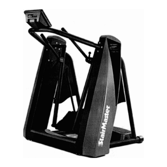
INTRODUCTION Before leaving the manufacturing facility Tulsa, Oklahoma, your StairMaster® FreeRunner™elliptical striding system was thoroughly inspected tested to ensure proper operation. The major parts of the machine are shown Figure GUARD COVER 22798 RIGHT) 22799 LEFT) TRANSPORT WHEELS Figure 1: Major Parts... -
Page 17: Table 1: Dimensions And Specifications
The dimensions genera specifications the machine are listed Table 1. Table 1. Dimensions and Specifications for the StairMaster® FreeRunner™ Elliptical Striding System Physical Dimensions: .5" (166 Height 42.0"(107 Depth 53.0" (135 Width 460.0... -
Page 18: Installation Instructions
INSTALLATION INSTRUCTIONS Your FreeRunner™ shipped complete with all parts required for assembly. Study the assembly instuctions carefully. The shipping components are shown below Figure 2. Contact our Customer Service Department at (800) 331-3578 assistance. International customers should contact their local distributors. -
Page 19: Figure 3: Tywrap Location
INSTALLATION INSTRUCTIONS Assemble the Machine: Cut each tywrap that secures the console handlebar to the rear support bars (see Figure 3). Remove the foam protection from each side of the handlebar. Lift the handlebar out from under the pedals. Set the handlebar with console aside. -
Page 20: Figure 4: Cable Locations
INSTALLATION INSTRUCTIONS Attach the console handlebar to the frame. To prevent the rivnuts (see Figure 4) from spinning in the frame, hold the rivnuts with pliers while securing the mounting screws to the frame. (PN 25165) TOP COVER BRAKE "NOTE: KEEP EXCESS SLACK IN CABLES AWAY FROM THE LEG SPROCKETS. Figure 4: Cable Locations Have an assistant help you slide the machine off the shipping pallet and onto the floor. -
Page 21: Figure 5: Level Adjusting End Caps
INSTALLATION INSTRUCTIONS B. Level the Machine: Make sure the machine is level before you use it for the first time. The rubber end caps (see Figure 5) are designed to compensate for uneven floors Each face of the caps is a different thickness. Twist the caps to stabilize the machine. -
Page 22: Figure 6: Dc Power Connector
Check to be sure that the input AC power rating marked on the power supply matches the available power. If it does not, obtain the matching power supply from StairMaster® Sports/Medical Products, Inc. before proceeding further. DC POWER CONNECTOR Figure 6: DC Power Connector Connect the AC power cord to the AC wall outlet. -
Page 23: Basic Operating Procedures
Although all equipment manufactured by StairMaster® Sports/Medical Products, Inc. has been thoroughly inspected by the manufacturing facility prior to shipment, proper installation and regular maintenance are required to ensure safety. -
Page 24: Your First Workout
YOUR FIRST WORKOUT ON THE STAIRMASTER@ FREERUNNERTM ELLIPTICAL STRIDING SYSTEM The ATTRACT Mode All workouts on the StairMaster FreeRunner elliptical striding system start from the ATTRACT mode. The console displays a factory set message or scrolls a custom message the text bar during the ATTRACT mode. -
Page 25: Figure 7: Correct Foot Placement
BASIC OPERATING PROCEDURES Figure 7: Correct Foot Placement for Stepping onto the FreeRunner™ Pedals Select the MANUAL exercise program so that you can control the pace of your first workout and get accustomed to the exercise motion. Press [MANUAL] and then press [ENTER]. The console will return to the ATTRACT mode you do not press [ENTER] within ten seconds. -
Page 26: Figure 8: Handle Adjustment
BASIC OPERATING PROCEDURES Swing the handle upwards and Pull the pin out to unlock release the pin to lock the handle the handle in position Figure 8: Handle Adjustment Begin Exercising Lean forward and take running strides without overextending your legs. The MANUAL program starts at intensity level three. -
Page 27: Figure 9: Correct Exercise Position
BASIC OPERATING PROCEDURES full resistance, and the brake will engage after both pedals have come to a complete stop. After the pedals are stopped, position yourself on the step before getting off the machine (see Figure 7) Cool down after you get off the machine by walking or stretching for at least five minutes. -
Page 28: Contact Heart Rate
CONTACT HEART RATE The StairMaster@ FreeRunner™ features a digitized contact heart rate monitoring system. Through the use of stainless steel sensors built into the console handlebar and sophisticated software, heart rate can be checked at any time during a workout. -
Page 29: Polar Heart Rate
POLAR HEART RATE StairMaster® FreeRunner™also features Polar® heart rate monitoring. The system consists of the receiver (see Figure 11), and a transmitter belt, worn across your chest. The transmitter belt (available separately) senses the heart beat and sends a signal to the receiver. Your heart rate, in beats per minute, is shown in the console text bar. -
Page 30: Console
FREERUNNER 5400 ESS CONSOLE StairMaster® FreeRunner™5400 ESS console is divided into four sections: the text bar, display, the function keypad, and the exercise program keypad (see Figure 12). TEXT BAR FREERunnER FUNCTION KEYPAD ::: _ _ aY --.-- DISPLAY EXERCISE PROGRAM KEYPAD... -
Page 31: Function Keypad
FREERUNNER 5400 ESS CONSOLE FUNCTION KEYPAD The white function keypad is located on the right side of the console. Some of the keys have two functions-data entry and workout statistics. Before you start your workout, use the numbers on the keys to enter your personal data. - Page 32 FREERUNNER 5400 ESS CONSOLE Speed. Shows the equivalent running speed in miles per hour (or kilometers per hour your console set to metric units) based on energy expenditure. If pressed immediately after your workout, the average speed displayed. Rate. Indicates the stride rate per minute.
-
Page 33: Exercise Program Keypad
FREERUNNER 5400 ESS CONSOLE EXERCISE PROGRAM KEYPAD The purple exercise keypad located below the display and to the left of the function keypad Press one of the exercise program keys to preview the desired workout while the console is in the ATTRACT mode. -
Page 34: Custom Exercise Programs
FREERUNNER 5400 ESS CONSOLE The Fat Burner Plus program is similar, but has gO intervals. Use this The Aerobic Training program is a 50-interval workout with slightly more varied speed changes. It is ideal for targeted workouts to increase your aerobic capacity. -
Page 35: Custom Scrolling Message
FREERUNNER 5400 ESS CONSOLE Using a Custom Program Press [DECREASE] and the exercise program keypad button you assigned to the custom program. Enter your body weight, the intensity level, and the workout time in response to the prompts. CUSTOM SCROLLING MESSAGE... -
Page 36: Editing The Scrolling Message
FREERUNNER 5400 ESS CONSOLE Table 2. Character Codes for the Scrolling Message Character Character Code Character Code Code SPACE EDITING THE SCROLLING MESSAGE Wh ile the console is in the ATTRACT mode, press [INCREASE], [7], [6], [0], [7], [ENTER] to display the first character of the message onto the text bar. -
Page 37: Chang Ing The Console Un Its & Prompt Language
FREERUNNER 5400 ESS CONSOLE To edit multiple characters at one time, press [9], [9], [ENTER] to erase all the characters to the right of the last character displayed on the text bar. To erase the entire message, press [INCREASE], [1], [0], [5], [ENTER], while the ATTRACT mode. -
Page 38: Table 3: Console Codes
FREERUNNER 5400 ESS CONSOLE Table 3. Console Codes FUNCTION CODE Clears the custom programmed scrolling message Activates the Diagnostic mode Software revision test Display test Speaker test Not used Keypad test Brake cycling test Limit switch test Not used Programs a custom workout... -
Page 39: The Jackpot Option
Thejackpot option remains in effect until disabled by entering zero odds. StairMaster assumes no liability stemm ing from the use of thejackpot option. Laws or ordinances in your area may govern the use of this option. -
Page 40: Maintenance Instructions
MAINTENANCE INSTRUCTIONS HELPFUL HINTS Read all maintenance instructions thoroughly before beginning work. some cases, an assistant required to perform the necessary tasks. All references to the left or right side, and to the front or back, are made as you were on the machine ready to exercise. For example, the console is located on the front of the machine. -
Page 41: Initial Service
MAINTENANCE INSTRUCTIONS INITIAL SERVICE Upon receiving your machine, use a soft, clean towel to wipe off the dust that may have accumulated during shipping. Your new machine will require minor assembly. Refer to the "Installation Instructions" section for details. PREVENTIVE MAINTENANCE A schedule of the recommended preventive maintenance shown in Table 4. - Page 42 Remove the covers to access the components. Place a protective mat on the floor whi Ie you lubricate your machine. rubber floor mat is available from StairMaster® Sports/Medical Products, Inc. Each week lubricate the entire length of the chains, and around each sprocket with cha in lube (e.g.
-
Page 43: Table 4: Recommended Preventive Ma Intenance Schedule
MAINTENANCE INSTRUCTIONS Table 4. Recommended Preventive Maintenance Schedule PART RECOMMENDED FREQUENCY CLEANER LUBRICANT ACTION N /A N /A Belts Inspect and adjust Every 3 months tension or 900 hours N /A Covers Clean and inspect Daily Soap and water, diluted household cleaner N /A Console... -
Page 44: Troubleshooting
TROUBLESHOOTING GENERAL TROUBLESHOOTING GUIDELINES This troubleshooting section organized into three basic problem sections: the Electrical System, Console Diagnostics, and the Mechanical System. Perform the tests exactly the same order as written. Refer to the "Parts Removal and Replacement" section of this manual for any assembly and disassembly instructions. - Page 45 TROUBLESHOOTING Plug the AC power cord back into the wall outlet. Disconnect the power supply from the machine. Use a multimeter to verify 16- 19 VDC at the end of the power supply DC cable. Pin #1 is positive, and pin #2 is negative.
- Page 46 TROUBLESHOOTING Perform the following Positive Output to Field test on the alternator: • Turn the power off. • Disengage the brake. • Remove the white wire from the B+ terminal on the alternator. • Remove the brown wire from the field (FLO) terminal on the alternator.
-
Page 47: Console Diagnostic Tests
TROUBLESHOOTING CONSOLE DIAGNOSTIC TESTS While the console is the ATTRACT mode, press [INCREASE], [1], [0], [7], [ENTER], to enter the DIAGNOSTIC mode. If the console fails any test, the console should be replaced or exchanged. To return to the ATTRACT mode, press [STOP] while in DIAGNOSTIC mode. - Page 48 TROUBLESHOOTING Firmly press each button. If the LED corresponding to the key you pushed does not light up, the keypad bad and the console should be replaced Press [STOP] to end the test. Software Revision Level Test This test will show you the revision...
-
Page 49: Systematic Mechanical Troubleshooting
TROUBLESHOOTING SYSTEMATICAL MECHANICAL TROUBLESHOOTING If you hear a grinding or clicking noise or experience excessive vibration during exercise, a problem exists the drive train of your machine. Isolate the problem area by performing the following tests in precisely the order listed below. - Page 50 TROUBLESHOOTING Check the pedal shafts and bushings by removing the pedal (see Figure 26). Inspect the shafts and bushings for signs of wear and corrosion. Clean corrosion off the pedal shafts with fine steel wool and replace any worn bushings before reassembling. DO NOT SAND THE PEDAL SHAFT. Reinstall all parts, ensuring proper tension of the POly-V pulley belts and that edge of the heel link pivot assembly is parallel with the floor...
-
Page 51: Parts Removal And Replacement
PARTS REMOVAL AND REPLACEMENT ALTERNATOR Remove the left side cover. Mark the location of each wire attached to the alternator (see Figure 36). Remove the wires and the diode from alternator. Remove the brake mounting bolt from the alternator (see Figure 13). -
Page 52: Bearings
PARTS REMOVAL AND REPLACEMENT BEARINGS Bearing Blocks - Heel Link Remove the side cover. Remove the pedal shaft housing from the pedal and pivot the pedal forward. Remove the heel link pillow block bearing,jam nut, and heel link sprocket. Use the heel link turnbuckle to loosen heel... -
Page 53: Pillow Block Bearings - Heel Link
PARTS REMOVAL AND REPLACEMENT Pillow Block Bearings - Heel Link Remove the side cover, Loosen the set screws on the pillow block bearings. Remove the two mounting screws and washers from the pillow block bearing and slide the bearing off the heel link shaft. -
Page 54: Lower Poly-V Belt
PARTS REMOVAL AND REPLACEMENT Loosen alternator screw and mounting bolt. Pivot the alternator down. Remove the belt (see Figure 14). Reinstall the belt. Pivot the alternator up or down as necessary to allow (0.6 cm) deflection at the midpoint between the two pulleys (see Figure 22). -
Page 55: Brake System
PARTS REMOVAL AND REPLACEMENT BRAKE SYSTEM Brake Actuator Arm Remove the left side cover. Remove the brake cam mounting screw from the top of the brake actuator arm. Loosen thejam nut from the center of the actuator arm, and remove the lower screw (see Figure 15). -
Page 56: Brake
PARTS REMOVAL AND REPLACEMENT "Brake Off" Brake Motor Switch Brake Cam Brake Cam Mounting Screw "Brake On" Switch Brake Brake Actuator Jam Nut Lower Screw Figure 15: Brake Location Brake Remove the left side cover. Remove the brake actuator arm from the brake. Remove the mounting bolt from the brake and lift the brake off the alternator flywheel. -
Page 57: Cables
PARTS REMOVAL AND REPLACEMENT CABLES Alternator Cable Remove the left side cover. Unplug the alternator cable from the power control board. Remove the wiring from the alternator, noting the origin and color of the wires removed from each terminal. Install the new cable and verify the wiring connections (see Figure 36). Reinstall the cover. -
Page 58: Polar® Heart Rate Cable
PARTS REMOVAL AND REPLACEMENT Replace each sensor grip, connect the cable to the console, and reinstall the console. Polar® Heart Rate Cable Disconnect the Polar heart rate cable from the console, and remove the right top cover. Note: When removing the top cover, lift up gently and disengage the Polar heart cable from the heart rate receiver located in the top cover (see Figure 11). -
Page 59: Upper Brake Cable
PARTS REMOVAL AND REPLACEMENT Upper Brake Cable Remove the console. Remove the left side cover. Unplug the upper brake cable from the lower motor control cable, and pull the upper brake cable out through the console handlebar. Thread the new cable into the console handlebar and plug the new cable into the lower brake cable. -
Page 60: Limit Switch Cable
PARTS REMOVAL AND REPLACEMENT limit Switch Cable Turn the power off and remove the left side cover. Unplug the motor cable and the limit switch cable from the power control board (see Figure 32). Remove the mounting screws from the upper and lower limit switches and remove the limit switch assembly. -
Page 61: Figure 16: Limit Switch Assembly
PARTS REMOVAL AND REPLACEMENT Motor Cable limit Switch ---Cable Brake Off Switch Trigger Points Brake On Switch Figure 16: Limit Switch Assembly Page 48... -
Page 62: Power Connector Cable
PARTS REMOVAL AND REPLACEMENT Power Connector Cable Remove the left side cover. Unplug the power connector from the power control board. Remove the four mounting screws and grounding screw from the frame. Remove the power connector cable from the frame Install the new cable, secure the grounding... -
Page 63: Lower Heel Link Chains
PARTS REMOVAL AND REPLACEMENT Support the upper heel link sprocket and remove the heel link from the heel link bearing block. Disconnect the master links from the upper heel link chains and install chains. Reinstall the heel link and ensure that the heel link shaft key is fully inserted into the key way. -
Page 64: Front Drive Chain Assembly
PARTS REMOVAL AND REPLACEMENT Note: It may be necessary to rotate the heel link turnbuckle both directions to see which way will loosen the chain. Disconnect the single pitch master links from each end of the chain. Pull the chain away from the lower heel link sprocket. Install the new chain. -
Page 65: Rear Drive Chain Assembly
PARTS REMOVAL AND REPLACEMENT Rear Drive Chain Assembly Remove the side and base covers. Rotate the drive chain turnbuckle to loosen the drive chain assembly. Remove the rear drive chain master links from each leg sprocket. Remove each pedal spring from the spring hanger and disconnect each step chain from each drive chain adapter link. -
Page 66: Console
PARTS REMOVAL AND REPLACEMENT Pull the step chain away from the drive sprocket and install the new chain. Reinstall the spring and verify that the spring is seated in the spring hanger groove. Note: Ifyou are having difficulty removing the left spring, remove the power control board for more accessibility. -
Page 67: Covers
PARTS REMOVAL AND REPLACEMENT COVERS WARNING TO REDUCE THE RISK OF INJURY, DO NOT OPERATE THE MACHINE WHILE THE COVERS ARE REMOVED. DO NOT MOVE THE PEDALS WHILE ANYONE'S HANDS INSIDE THE MACHINE. Base Cover Remove the side covers. Remove inside mounting rivet from each side... -
Page 68: Step Cover
PARTS REMOVAL AND REPLACEMENT Lift the side cover up and remove it from the frame. Install the new side cover by aligning the cover hooks with the frame pins and tightening the wing nuts. Reinstall the top cover. Step Cover Remove the two screws and washers from the step cover and Iift the step cover off the step. -
Page 69: Handle Assembly
PARTS REMOVAL AND REPLACEMENT Remove the drive sprocket, thrust washers, thrust bearings, and spacers from the drive shaft (see Figure 23). From the right side, remove the snap ring, washers, bearings, drive sprocket from the drive shaft and slide the shaft out from the frame Install shaft and reassemble the machine. -
Page 70: Heel Link
PARTS REMOVAL AND REPLACEMENT HEEL LINK Remove the pedal (see Figure 26). Remove the snap ring from the heel link pivot assembly. WARNING TO REDUCE THE RISK OF EYE INJURY, WEAR EYE PROTECTION WHEN REMOVING SNAP RINGS. Separate the heel link from the pivot assembly. Install the new heel link and reinstall the pedal. -
Page 71: Leg Assembly
PARTS REMOVAL AND REPLACEMENT LEG ASSEMBLY Remove the pedal assembly. Remove the side cover. Remove the spring from the spring hanger, and loosen the drive chain assembly turnbuckle (see Figure 20). Loosen the leg sprocket set screws (see Figure 24). Remove the leg assembly pillow block bearing. -
Page 72: Mounting Blocks
PARTS REMOVAL AND REPLACEMENT MOUNTING BLOCKS Remove the covers. Have an assistant help you prop the front of the machine up with wooden blocks. Be careful not to block access to the mounting screws Remove the front and rear drive chain assemblies. Remove the step chains and heel link chains. -
Page 73: Pedal Return Springs
Remove the snap rings and washers from the pedal shafts. WARNING TO REDUCE THE RISK OF EYE INJURY, WEAR EYE PROTECTION WHEN REMOVING SNAP RINGS. Slide the pedal assembly off the pedal shafts and remove the remaining washers. Install the pedal assembly reverse order. -
Page 74: Pulleys
PARTS REMOVAL AND REPLACEMENT Unplug the lower brake cable, alternator cable, lower main cable, stride sensor cable, load resistor cable, brake motor cable, and power connector from the power control board (see Figure 32). Remove the two mounting screws from the board, and set the board aside. Apply a thin coat of heat sink grease on the aluminum block of the new power control board,... -
Page 75: Intermediate Poly-V Pulley Assembly
PARTS REMOVAL AND REPLACEMENT Remove the upper and lower POly-V belts. Remove the mounting bolt and washer from the pulley, and slide the pulley assembly off the shaft. Install the new pUlley assembly, and install the belts. Install the upper POly-V belt and pivot the alternator up or down as necessary to allow of deflection at the midpoint between the two pulleys (see Figure 22) -
Page 76: Step
PARTS REMOVAL AND REPLACEMENT Remove the step. Remove the mounting bolts and washers from the rear support bar and remove the rear support bar from the frame. Install the new rear support bar, and have an assistant help you tilt the machine back into place. -
Page 77: Spring Cartridge
PARTS REMOVAL AND REPLACEMENT Have an assistant help you tilt the mach ine forward onto console handlebar. Loosen and remove the spring cartridge mounting bolts from frame Remove the spring cartridge. Install the new spring cartridge, connect the lower heel link chains and have an assistant help you tilt the machine back into place. -
Page 78: Drive Sprockets
PARTS REMOVAL AND REPLACEMENT Reassemble the mach ine in reverse order, adjust the top edge heel link pivot assembly so that it is parallel with floor (see Figure 29). Drive Sprockets Remove the side cover. Remove the lower POly-V belt, and remove the snap ring, washers, lower... -
Page 79: Leg Assembly Sprockets
PARTS REMOVAL AND REPLACEMENT Loosen the heel link turnbuckle (see Figures 19 and 20), and remove the heel link pillow block bearing Unhook the extension spring from the spring hanger. Remove thejam nut and washer from the heel link assembly shaft. Support the sprocket with chains... -
Page 80: Grounding Instructions
GROUNDING INSTRUCTIONS The external power supply must be grounded. Grounding provides the path of least resistance the electric current, thereby reducing the risk of electric shock. The power supply must be plugged into an appropriate outlet that properly installed and grounded accordance with all local codes and ordinances. -
Page 81: Notice Of Fcc Compliance
• Consult the dealer or an experienced radio/TV technician for help. WARNING CHANGES OR MODIFICATIONS TO EQUIPMENT NOT EXPRESSLY APPROVED BY STAIRMASTER®SPORTS/MEDICAL PRODUCTS, INC. COULD VOID THE USER'S AUTHORITY TO OPERATE THIS EQUIPMENT. The contact heart rate sensors are electrostatic discharge (ESD) sensitive. -
Page 82: Important Phone Numbers
IMPORTANT PHONE NUMBERS If you need assistance, please have both the serial number of your machine and the date of purchase available when you contact the appropriate StairMaster® Sports/Medical Products, Inc. office listed below. OFFICES IN THE UNITED STATES CORPORATE HEADQUARTERS... - Page 83 APPENDIX Figure Final Assembly· Left Side DETAIL A UPPER FRONT DRIVE CHAIN #40,24.5- (PN 21826) UPPER REAR DRIVE CHAIN #40, 12.5- (PN 21866) STRIDE SENSOR (PN 25112) LEG ASSEMBLY PILLOW BLOCK BEARING POWER CONTROL BOARD (PN 252471 (PN 25102) LOAD RESISTOR HEEl LINK PILLOW (PN 25121) BLOCK BEARING...
-
Page 84: Figure 20: Final Assembly - Right Side
APPENDIX Figure 20: Final Assembly· Right Side DETAIL A UPPER REAR DRIVE CHAIN UPPER FRONT DRIVE CHAIN #40,24.5" #40, 12.5" (PN 21866) IPN 21826) LEG ASSEMBLY PILLOW BLOCK BEARING IPN 252471 HEEL LINK CHAIN #40, 5.5" IPN 205321 EXTENSION SPRING IPN 219261 HEEL LINK TURNBUCKLE ASSY IPN 218521... -
Page 85: Figure 21 : Chain Assembl Ies
APPENDIX Figure 21: Chain Assemblies #40. 24.5" 2XPN 21826 DOUBLE PITCH MASTER LINK 8 X PN 20329 PEDAL RETURN SPRING ® 2 X PN 21093 2UPPERHEELLINKCHAIN 2X PN 21905 ITURNBUCKLEASSEMBLY 3 X PN 21852 CHAIHUHK 30.25" 2XPH 22740·05 LOWER REAR DRIVE CHAIN 1XPH 21907 SPRING CHAIN CONNECTOR... -
Page 86: Figure 22: Belt Tension
APPENDIX Figure 22: Belt Tension ALTERNATOR ASSEMBLY BRAKE (PN 226661 UPPER POLY -VBElT 21599) INTERMEDIATE POLY-VPULLEY ASSEMBLY IPN 25216) LOWER POLY-V BELT Page 73... - Page 87 SCREW (2 XPN 252111 SCREW > < PN 28233) WASHER (2 X PN 222221 THRUST BEARING HEEL LINK (4 X PN 201981 IDLER SPROCKET (2 X PN 25249) SNAPRING (2 X PN 20206) DRIVE SHAFT SPACER (PN 22781) DRIVE SHAFT (10) (PN 227111 DRIVE SHAFT KEY...
- Page 88 LEG SHAFT KEY (PN 22758) MOUNTING SCREWS (4 XPN 22204) BEARING BLOCK ASSEMBLY SET SCREW (PN 25197) • (PN 22037) WASHER • SPLIT LOCK IPN 251811 LEG ASSEMBLY PillOW BLOCK (PN 25279 LEFT) BEARING (PN 25280 · RIGHT) (PN 21816·03) SCREW JAM NUT (2 XPN 25256)
- Page 89 HEEL PIVOT THRUST BEARING (PN 22672 0LEFT) (2 XPN 22232) BEARING BLOCK (PN 22673 0RIGHT) ASSEMBLY SNAP RING (PN 20213) HEEL PIVOT ..,., WASHER SHAFT KEY SPUTLOCK (PN 218331 (PN 25181) SPROCKET 21892005) HEEL LINK ASSEMBLY (PN 22717·03· LEFT) PILLOW BLOCK (PN 22719.03 0 RIGHT) BEARING (PN 24546)
- Page 90 APPEN 'D "IX Figure 26: Pedal M ountmg SNAP RING (2 XPN 20213) 1 WASHER 12XPN2187l) 2 THRUST WASHER 12 XPN 21937) SPACER 12 X PN 25286) Page 77...
-
Page 91: Figure 27: Pedal Assembly
..APPENDIX Figure 27: Pedal Assembly PEDAL STRAP (PN 21862) RIVETS (6 XPN 22086) PEDAL COVER (PN 21817) PUSH NUT FASTENER (6 XPN 20508) PEDAL SUPPORT 22690) PEDAL SHAFT HOUSING* (PN 22692) *INCLUDES PRESSED·IN BRONZE BUSHING· PN 20002 Page 78... -
Page 92: Figure 28: Master Links
APPENDIX Figure 28: Master Links DOUBLE P ITCH MASTER LINK (PN 203291 D IRECTION OF CHAIN TRAVEL SINGLE PITCH MASTER LINK (PN 253051 DIRECTION OF CHAIN TRAVEL Page 79... -
Page 93: Figure 29: Heel Link Pivot Adjustment
APPENDIX Figure 29: Heel Link Pivot Adjustment USE TlfE HEEL LINK TURNBUCKLE TO ADJUST THE TOP EOGE OF THE HEEL LINK PIVOT ASSEMBLY SO THAT IS PARALLEL TO THE FLOOR ALIGN THE TOP EDGE OF THE PIVOT PARALLEL TO THE FLOOR - - - - - - Page 80... -
Page 94: Figure 30: Handle Assembly
APPENDIX Figure Handle Assembly HANDLE KNOB PIN 25251·05) SPRING (PN 252501 - - HANDLE KNOB IPN 24042) HANDLE ASSEMBLY 25217) Page 81... -
Page 95: Figure 31: Limit Switch Assembly
APPENDIX Figure 31: Limit Switch Assembly BLACK WIRE -BRAKE MECHANICAL STOPS BRAKE CAM 21840) ·PART OF THE LIMIT SWITCH ASSEMBLY (PN 27002) GREEN WIRE BRAKE ACTUATOR ARM Page 82... -
Page 96: Figure 32: Power Control Board "A
APPENDIX Figure 32: Power Control Board"A" FREERUNNER POWER CONTROL BOARD 25102) Page 83... -
Page 97: Figure 33: Led Panel
APPENDIX Figure 33: LED Panel LED PANEl POWER CONTROL BOARD - UGHT EMmlNG DIODES (LEOs) #1 - V SiP ply • the power supply is operating check the following wall outlet, power supply, power connector, and power control board VCC- power is getting to the console, and if the console is providing +5V back down to the power control board If -OFF-, check the... -
Page 98: Figure 34: Power Control Board "B
APPENDIX Figure 34: Power Control Board "B" Pins: CONSOLE PLUG-IN (On the PCB Board) Pin 1 - Alt Off Pin 2 - V Supply Pin 4 - Resistor Control Pin 7 - Tach Pin 8 - N/C Pin 9 - Stride Sensor Pin 10- Ground Page 85... -
Page 99: Figure 35: Console Main Cable
APPENDIX Figure Console Main Cable VIEW B· B CONSOLE MAIN CABLE Pin 1 - V-Supply Pin 2 - BROWN Art Off 3 - RED Scaled 4 - ORC Re"i3tor Control Pin 5 - YELLOW Pin 7 - Ground Pin 8 - VIO Stride Sensor Pin 9 - NIC... - Page 100 ... APPEN X 36· Alternator Cable Figure ALTERNATOR CABLE (White vyire) Pin 1 - 8+ d !Black Wire) VIEW A· Pin 2 - (Brown Wire) Pin 3 - Field (Blue Wire) Pin 4 - Tach DIODE Page 87...
-
Page 101: Figure 37 : Power Supply
APPENDIX Figure 37: Power Supply POWER SU PPlY Pin 1 . VSupply Pin 2 . Ground Pin 3 . Earth Ground Pins: Page 88... -
Page 102: Figure 38: Load Resistor
APPENDIX Figure 38: Load Resistor TO WIRE LOAD RESISTOR 1/2 Ohm 240 Watt 1/2 Ohm measured at Pins 1 and 3 Page 89...
Need help?
Do you have a question about the FreeRunner 5400 ESS and is the answer not in the manual?
Questions and answers