Stairmaster StepMill 5 Assembly Manual
Stepmill 5
Hide thumbs
Also See for StepMill 5:
- Owner's manual (42 pages) ,
- User manual (37 pages) ,
- Owner's manual (37 pages)
Table of Contents
Advertisement
Quick Links
Advertisement
Table of Contents

Related Manuals for Stairmaster StepMill 5


Summary of Contents for Stairmaster StepMill 5
-
Page 1: Assembly Manual
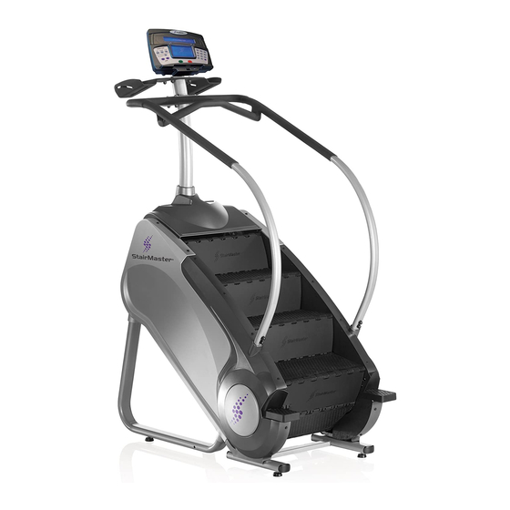
StepMill 5 ® Assembly Manual 150005-083011A... -
Page 2: Table Of Contents
Hardware ....................................6 Box Contents ..................................... 7 Assembly .....................................9 Mast Hardware Detail ................................16 Handrail Hardware Detail ..............................17 Contacting StairMaster .................................18 Product Specifications Model SM5 34" W x 58" L x 89" H ( 86 cm x 147 cm x 226 cm) Dimensions:... -
Page 3: Safety Warnings
Examine this machine for loose parts or signs of wear. Pay special attention to the steps. Contact StairMaster® Customer Service for repair information. Use only genuine StairMaster® replacement parts. Set up and operate your StepMill® on a hard, level surface. -
Page 4: Safety Caution And Warning Labels
Safety Caution and Warning Labels ® Before using your product : Find and read all warning labels located on the StairMaster StepM ill ® 5, prior to using your product. Be sure to replace any warning label if damaged, illegible, ®... -
Page 5: Before You Start
Before You Start ® ® Locate the area where you will assemble and use your StairMaster Commercial Series StepMill We recommend you install it on a hard, level surface. Allow an assembly area of at least 36” (0.91 m) on each side and behind the machine. You can put the rear of the machine closer to the wall during use. -
Page 6: Hardware
Hardware Hardware Item # Description 5/16 " - 18 *1 3/4” Button Head Screw 3/8 " - 16 * 1" Button Head Screw 1/4 " - 20 * 3/4" Phillips Head Screw 3/8” - 16 * 1 3/4” Button Head Screw 5/16”... -
Page 7: Box Contents
Box Contents Item # Description Assembly Manual Owner’s Manual Kit Rivet Puller Rivet Levelers Hardware Card #1 Hardware Card #2 Top Cover Power Supply & Power Cord Kit Cover Handrail Left Cover Handrail Right Assembly Manual... - Page 8 Box Contents Console Options Item # Descritpion Console Mast Touchscreen or LCD Console Upper Handrail Assembly Water Bottle Holder Lower Handrails Rubber Sleeve (Console Mast) Rubber Sleeve (Handrails) Wheel Panel Left Wheel Panel Right Wheel Plate Bracket Mast Mount End Cap Assembly Manual...
-
Page 9: Assembly
Assembly The following instructions provide direction to assemble the StairMaster ® StepMill ® 5. All instructions in the manual are given with the orientation of standing on a level surface and facing the machine. (See Figure 1) Step 1: Unpacking the StepMill 5... - Page 10 Assembly Step 3: Attach Handrail 3-1 Secure item #3(Bracket Mast Mount) to frame 3-2 Slide item #35(Rubber Sleeves Handrail) below the bolt holes on item #33(Lower Handr 3-3 Attach item #33(Lower Handrails) to mounting frame posts using hardware items #4, #10, #8, Figure 3-4 Standing at the front of the SM5, attach item #31(Upper Handrail Assembly) to items #33 using...
- Page 11 Assembly Step 4: Attach Mast 4-1 Slide item #29(Console Mast) through the handrail assembly, through item #34(Rubber Sleeve), and through 4-2 Route console wires and coax cable up through item #29 routing console wires and coax cable. Figure 4A 4-3 Secure item #29(Console Mast) to item #39(Bracket Mount) 4-4 Secure item #31(Upper Handrail Assembly) to item #29 (Console Mast) by using hardware items #6, #14, 11, and 4-5 Fasten all bolts, slide item #25(Top Cover) and item #34...
- Page 12 Assembly Step 5: Attach Water Bottle Holder 5-1 Attach item #32(Water Bottle Holder) on top of mast plate using hardware items #2, #14, #8, and #11. 5-2 Secure item #40(Mast Cap) onto top of mast Figure Step 6: Install Console 6-1 Connect the wiring and power harness to their respective locations in the back of the console.
- Page 13 Assembly Step 7: Attach Lower Platics 7-1 Attach items #36(Wheel Panel Left) and #37 (Wheel Panel Right) to main frame using hardware 7-2 Attach items #27(Cover Handrail Left) and #28 (Cover Handrail Right) to main frame using hardware Note: Ensure items #36 mates with #27 and #37 mates with #28.
- Page 14 Assembly Step 9: Remove Transport Wheels Use a second person when performing assembly steps requiring heavy lifting or awkward movements. 9-1 Roll the StepMill ® machine to the workout location. 9-2 With the assistance of another person, tilt the StepMill ®...
- Page 15 Assembly Step 10: Connecting Power Supply 10-1 Connect the DC Power Cable from the Power Supply to the power connector located on the bottom cover (Figure 10). 10-2 Place the Power Supply on the floor near an AC wall outlet. 10-3 Check that the Input AC Power Rating marked on the Power Supply matches the available power.
-
Page 16: Mast Hardware Detail
Mast hardware detail Item #’s listed in balloons Assembly Manual... -
Page 17: Handrail Hardware Detail
Handrail Hardware detail Item #’s listed in balloons Assembly Manual... -
Page 18: Contacting Stairmaster
E-mail: parts@stairmaster.com services@stairmaster.com Please supply the serial number of your machine and the date of purchase when you call StairMaster. Use the space in the boxes below to write down this information. To d the serial number on your machine, refer to the Safety Warning Label information page. - Page 19 © 2011 Core Fitness, LLC, dba StairMaster. All rights reserved. StairMaster and the StairMaster logo are either registered trademarks or trademarks of Core Fitness, LLC. All other trademarks are owned by their respective companies. StairMaster, 4400 NE 77th Ave, Suite 300, Vancouver, WA 98662 1-888-678-2476 | www.stairmaster.com...
Need help?
Do you have a question about the StepMill 5 and is the answer not in the manual?
Questions and answers