Table of Contents
Advertisement
Advertisement
Table of Contents
Troubleshooting

Related Manuals for Stairmaster 8G Gauntlet


Summary of Contents for Stairmaster 8G Gauntlet
- Page 1 Core Health & Fitness 8 Series Gauntlet SERVICE MANUAL...
- Page 2 StairMaster 8G Gauntlet Product Details & General Features • Part Identification & Component Theory • • Installation Wiring / Wiring Diagram • • Power Flow • Signal Flow Preventative Maintenance • • Troubleshooting & Part Replacement Page 2...
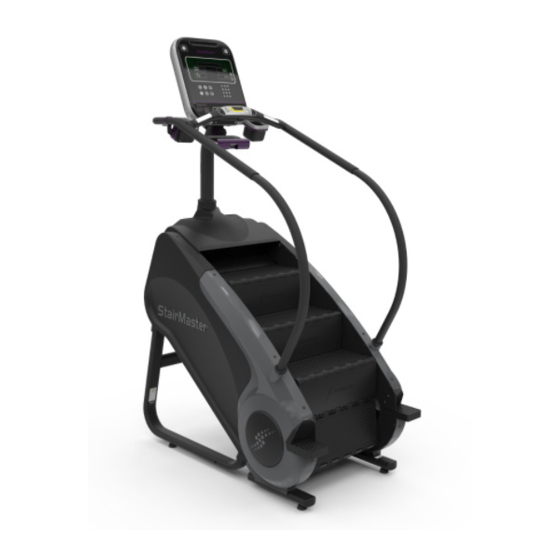
- Page 3 MEET THE MACHINE THE ENTIRE GYM LOOKS UP TO. Beginning with the first stepping machine in 1983, StairMaster® has been a legendary name in the gym. Today the tra- dition continues with the Gauntlet®. Building on 30 years of experience and proven performance, the Gauntlet provides a superior combination of cardio and strength training in our most comfortable design ever.
-
Page 4: Preventative Maintenance
Preventative Maintenance With durable, high performance components, the 8 Series Gauntlet is designed for heavy usage with minimal main- tenance required. To keep it in top condition, perform regular daily, weekly, and monthly preventative maintenance routines outlined below. It is the sole responsibility of the owner of this equipment to ensure that regular maintenance is performed. - Page 5 Part Identification & Component Theory Drive System The 8G drive system is a 3 part system that combines an alternator that provides resistance, a gear box that handles the torque load and to ensure gearing up/down is handled appropriately during a user workout and while braking, and the brake that prevents the steps from moving while stopped.
- Page 6 The upper and lower sprockets are held to the Bearing Plate Bearing Plate chassis of the machine by pillow block bearings and Frame Frame connect the left-side and right-side step chains. Upper Sprocket Pillow blocks can be adjusted on the frame to en- Pillow Block Bearing Pillow Block Bearing sure alignment from upper to lower sprockets and...
- Page 7 The alternator in the 8G is the same as in earlier Stairmaster models, including wiring. Wiring details are on the next page and also in the troubleshooting section of this manual.
- Page 8 Step Hardware Step Step Hinge Sha� Hinge Clip Step Riser Step Chain Step Sha� The steps on the 8G are a composite plastic step with a rubber tread built into step top. The step top and kick plate are held together and to the step chains by step hinges, threaded step shafts, nylon spacers, bearings, washers, and bolts. Step Riser Step Riser Step Chain...
- Page 9 Major Components of the Drive System The detail view of the 8G with the drive train isolated (above) shows the upper sprocket connection to the gear box via drive chain. The gear box is in place to ensure gearing up/down is handled appropriately during a user workout. The upper sprocket has an inner sprocket that connects the drive chain to the gear box sprocket.
- Page 10 Major Components of the Power System Battery 6VDC LCB 711-3461 Cable to RPM Sensor Main Data Cable to Display Alternator Cable Harness Load Resistors Power enters the system through a power converter brick plugged into the wall. It runs through an EMI filter into the LCB where it is distributed to the rest of the system based on console signals.
- Page 11 Installation 1. Remove all parts from the box Remove all the packaging material and parts not attached to unit including shrouds, mast, hardware card, etc. so the 8G Stepmill is ready for assembly on the shipping crate platform. Move the main as- sembly carefully off the shipping pallet.
- Page 12 2. Install the Neck Bracket Secure the Frame Neck Adapter to the frame using four (4) pieces each of the 5/16”x1 3/4” screws, 21mm OD washers, and 5/16” nylok hex nut. 3. Rout Cables Through Mast Slide the Mast Grommet onto the mast first and then the Upper Shroud Cover Route the wires for the display up and out through the top of the mast.
- Page 13 5. Secure Side Rails to Frame Slide the Left Handrail Grommet onto the Lower Left Handrail then repeat this step for the Right Handrail Grommet and Lower Right Handrail. At- tach handrails with (2) pieces each of the 3/8”x1” screws and 3/8” nylok hex nuts and (4) pieces of the Ø3/8”...
- Page 14 8. Reinstall Shroud Cap Attach the Lower Right Handrail Cover using the plastic rivets then repeat for the Lower Left Handrail. Slide the Lower Handrail Grommets down and ensure a tight seal against the Lower Shrouds and Lower Handrail Covers. 9.
- Page 15 11. Connect cables to Console Board Connect the appropriate wires coming out of the mast to the correct locations, please reference the console wiring guide (CSB 620-8424). 12. Secure Display Secure the front half of the console assembly to the back half using the screws supplied with the console taking care not to pinch any wires and ensuring that the rubber console grommet has a good seal.
- Page 16 14. Clamp the Power Cord Remove the Phillips screw and place the power cord into the clip. Then reinstall the screw. 15. Installation is Complete Plug power into wall and perform final checks. Note: Be sure to set the display to correct model in the Maintenance Mode.
- Page 17 Wiring Diagrams To Display 12VDC Main Power Harness W/Power Inlet (711-3495) EMI Filter 12VDC (440-0282) 12VDC Resistor Assy (711-3242) 24VDC IN USE Alternator/Brake/Transmission Assy (711-3510-KT) 3VDC Battery (580-0275) Speed Sensor (140-3501) 7VDC 3VDC Alternator Cable Harness (711-3351) Main Data Cable ALL VOLTAGES GIVEN WHILE MACHINE NOT IN USE (711-3494) To Display...
- Page 18 Power Flow A power trace tests the voltage at every junction point of electricity on the machine from the wall to the console to validate good power flow and eliminate power as part of routine troubleshooting. Refer to the diagram above for the general flow of a power trace of the 8G.
- Page 19 Test the power cord that connects the pow- er adapter to the wall socket for 110VAC OR 220VAC* *Voltage and current can vary depending on country. Test for 12VDC coming from the power supply via the barrel connection. One probe should be in- side the barrel connector while the 2nd probe is touching the outside of the connector as shown.
- Page 20 Test for 12VDC coming out of the EMI filter Test for 9VDC coming out of the lower control board (LCB) going to the main data cable Test for 9VDC coming out of the main data cable going to the console Page 20...
- Page 21 15 “ Embedded OR 10” Touch screens OR Per- onal Viewing Screen (PVS) Only: Test for 12VDC supplementary power coming from the power inlet cable going to either the 10” touchscreen, 15” embedded, or PVS Enter maintenance mode by pressing “0 + 2 + OK”...
- Page 22 Test for 3VDC going through the alternator. One probe should be on the B+ post while the other probe is on the Field post. Removal of the Field wire may be necessary to get a clear reading. Test for 7VDC going to the battery from the alter- nator harness.
- Page 23 All TV/Cable signals in the 8G are pass-through signals to the console. Coax cable for TV signals is plugged into the lower right leg of the 8G and connects to an internal coax cable that goes through the head to the console. 8G Gauntlet Signal Flow Alternator...
- Page 24 Troubleshooting & Part Replacement: Please note: information in this document reflects the bulletins published at the time this document was made. For the most recent updated document, please refer to our support site. Troubleshooting Triage To return to this page directly, click the icon at the end of a troubleshooting section.
- Page 25 Electronic issues • Clearing a Error Code 44 - SPM Overflow message on the console screen • The hot bar buttons don’t respond to input • The LCB software needs to be updated Mechanical issues • The steps freewheel/have no resistance •...
- Page 26 Appendix Titles below highlighted in yellow have been changed or added since the last revision. Document Title Doc. Ctrl. Rev. 8G Brake Assembly Alignment 637-4306 8-G Brake Clicking, No Step Movement 637-4392 8G Engine Replacement Procedure 637-4360 8G Power Trace 637-4523 Alternator Replacement 637-4489...
- Page 27 Gear Box and Belt Replacement 8-G (9-5250) Doc. #637-4490 This document reviews the process to replace the gear box and the drive belt in the 8-G stepmill. Tools Required: • 1/8” Allen Key • 7/16” Socket • ½” Socket • 3/4”...
- Page 28 Use a 1/8” allen key to loosen the gear box sprocket set screws Push the idler arm up to release ten- sion on the chain, walk the chain off of the idler sprocket, then pull the chain and gear box sprocket off of the gear box shaft.
- Page 29 Use a 7/16” socket to loosen the four (4) bolts securing the gear box to the frame. Once the bolts are loose, slide the gear box/alternator assembly towards the user left side and the as- sembly should drop free of the frame. NOTE: On some older 8-Gs, the gear box bolts will need to be completely removed.
- Page 30 Use a 7/16” socket to remove the four (4) bolts on the bottom of the gear- box assembly. Once the bolts have been removed, slide the gear box out from the pulley. The belt and gear box can both be replaced at this point.
- Page 31 Alternator Replacement 8-G (9-5250) Doc. #637-4489 This document reviews the process to replace the alternator on the 8-G stepmill. Tools Required: • 1/8” Allen Key • 7/16” Socket • ½” Socket • 3/4” Socket Remove the four (4) rivets securing the user left side shroud to the frame, then remove the user left shroud.
- Page 32 Use a 1/8” allen key to loosen the gear box sprocket set screws Push the idler arm up to release tension on the chain, walk the chain off of the idler sprocket, then pull the chain and gear box sprocket off of the gear box shaft. NOTE: Take care not to lose the key that may drop from the gear box shaft.
- Page 33 Use a 7/16” socket to loosen the four (4) bolts securing the gear box to the frame. Once the bolts are loose, slide the gear box/ alternator assembly towards the user left side and the assembly should drop free of the frame.
-
Page 34: Tools Required
Step Chain Replacement SM5 (150005) + Gauntlet (155005) + 8-G (9-5250) Doc. #637-4508 Tools Required: • 3/16” Allen Key • 1/2” Socket • Small Crescent Wrench • Flat Head Screwdriver Remove the four (4) rivets securing the user left body panel to the frame (Fig. 1). To remove the rivets, first push down on the center post of the rivet until a ‘click’... - Page 35 Locate the master link on the drive chain (Fig. 3). Fig. 3 Use a flat head screwdriver to remove the master link clip (Fig. 4) Fig. 4 Page 35...
- Page 36 Remove the drive chain master link (Fig. 5) and the drive chain. This will allow the steps to turn without releasing the brake. REMINDER: Be sure to reconnect the drive chain before securing the shrouds when finished with the step chain replacement. Fig.
- Page 37 Locate the master link on the step chain (Fig. 7) and remove it using the same process as steps 4 + 5. Fig. 7 Using the master link removed in step 7, attach the end of new step chain to the old step chain where the master link was removed (Fig.
- Page 38 Use a small crescent wrench to hold the stepshaft nut on one side of the stepshaft while using a 1/2” socket to remove the nut on the opposite side. Be sure to remove the step shaft nut on the same side as the replacement step chain. Once the nut is removed, also remove the bearing and washer from the stepshaft (Fig.
- Page 39 Slide two lengths of the new step chain onto the exposed stepshafts and secure using the hard- ware removed in step 9. NOTE: A portion of the new stepchain has been removed to show clarity. Fig. 11 Turn the steps backwards so that they move up the unit and repeat steps 9 - 11 until the new step chain is secured to the remaining stepshafts and the old step chain has been completely...
- Page 40 8G Power Trace 8G (9-5250) Doc. #637-4523 This document reviews the power-trace procedure for the 8-G Stepmill. This guide begins after the shrouds of the unit have already been removed. Tools Required: • Multi-Meter • Phillips Screw Driver ALL VOLTAGES GIVEN WHILE MACHINE IS NOT IN USE Using a multi-meter, test the wall outlet for 110VAC OR 220VAC* (Fig.
- Page 41 Test for 12VDC coming from the power supply via the barrel connection (Fig. 3). One probe should be inside the barrel connector while the 2nd probe is touching the outside of the connector as shown. Fig. 3 Test for 12VDC coming from the power inlet cable into the EMI filter (Fig.
- Page 42 Test for 12VDC coming out of the EMI filter (Fig. 5). Fig. 5 Test for 9VDC coming out of the lower control board (LCB) going to the main data cable (Fig. 7). Fig. 7 Page 42...
- Page 43 Test for 9VDC coming out of the main data cable going to the console (Fig. 8) Fig. 8 15 “ Embedded OR 10” Touch screens OR Per- onal Viewing Screen (PVS) Only: Test for 12VDC supplementary power coming from the power inlet cable going to either the 10” touchscreen, 15”...
- Page 44 Enter maintenance mode by pressing “0 + 2 + OK” at the same time. Then scroll using the level up/down button. Use the “OK” button to select “BRAKE TEST” MAKE SURE THE STEPS ARE CLEAR OF TOOLS AND NO ONE IS STANDING ON THEM use the level up/down button to scroll to “OFF”...
- Page 45 Test for 3VDC going through the alternator (Fig. 12). One probe should be on the B+ post while the other probe is on the Field post. Removal of the Field wire may be necessary to get a clear reading. Fig. 12 Test for 7VDC going to the battery from the alter- nator harness (Fig.
- Page 46 A fully charged battery should top out at 7VDC. A battery that reads less than 6.7 VDC is consid- ered ‘dead’ and should be replaced. Fig. 14 Page 46...
- Page 47 Alternator Testing All Stepmills Doc. #637-4509 This document details the procedure for troubleshooting and testing a suspected bad alternator. It applies to any unit that uses the SM22900 or SM20205 (not available from Core) alternator. The older SM20205 alternator was used on the 7000PT and SM916 units and can be replaced by the new alter- nator, however light users will have difficulty making the steps move on those units.
- Page 48 No Resistance When Stepping Check alternator brush length. Remove user-right side cover Remove brown wire from W3 (FLD BRN) post of alternator. Loosen ¼” bolts on W3 post. Remove and verify brush length and quality. We recommend replacing brushes that are ¼” or less. Good Alternator Brush Length ( >0.25”) Remove the right side panel to view the three LED’s on the lower PCB board.
- Page 49 Test Points Status LEDs Main Cable Socket Power Conn. Socket W-5 : White W-4 : Blue W-3 : Brown W-2 : Black W-1 : White Relay Board Detail (Prior to 8G) Relay Board Tests Perform the following testing to verify the integrity of the relay board. Refer to the diagram on the previous page for the location of the test points.
- Page 50 Once the test is completed, re-attach the black W-2 ground wire and the J-1 main cable socket which was re- moved at the beginning of the relay board test. Battery 6VDC LCB 711-3461 Cable to RPM Sensor Main Data Cable to Display Alternator Cable Harness Load Resistors 8G Relay Board Assembly...
- Page 51 Staircase has Resistance but is Choppy During Exercise Use these instructions if you have already cleared a mechanical inspection for parts interfering with the steps. Generally, the issue with choppy/sticking steps is more commonly traced to a physical issue rather than an electrical one. Inspect Main Cable for Corrosion at all connections.
- Page 52 8-G Brake Clicking, No Step Movement 8G (9-5250) Doc. #637-4392 This document reviews the possible scenarios around the 8-G steps not moving after the brake clicks and unlocks. Symptoms of this may be no step movement at all, or restricted step movement while the display is in a program. This can also be described as a sticking feeling, or possibly no step movement for lighter weight users.
- Page 53 To correct this, use a 1/8” allen key to loosen the two (2) gearbox set screws, then pull the sprocket away from the body of the gearbox until clearance is achieved. Be sure to tighten the set screws after spacing the sprocket. If the unit is still experiencing the issue after spacing the sprocket away from the gearbox, check the following to ensure there is no mechanical binding in the rest of the unit: Check to ensure all wires are secured away from the steps and chains.
- Page 54 8G Brake Assembly Alignment 8G (9-5250) Doc. #637-4306 This document explains how to do the 8G (9-5250) brake assembly alignment in order to eliminate noise in the drive system coming from the mis-aligned brake plates. Tools Required • 1/8” hex key •...
- Page 55 Use a 1/8” hex key to loosen the transmis- sion sprocket set screws Push up on the idler sprocket to release tension on the chain, then walk the chain off of the idler sprocket Pull the transmission sprocket off of the transmission, be careful not to lose the key for the sprocket Page 55...
- Page 56 Use a ½” socket to remove the bolt con- necting the transmission to the alternator via the alternator bracket then walk the alternator belt off of the alternator. Cut any zip ties holding the black cable running from the brake to the lower board Remove the two (2) screws securing the clear plastic shield that covers the lower board using a Phillips screwdriver...
- Page 57 Unplug the black/white brake cable from the PCB Wrap a belt or large zip tie around the mid- dle of the transmission shaft and the frame to act as pressure relief for the next step Use a 7/16” socket to remove the four (4) screws that hold in the transmission to the frame, remove the strap securing the transmission to the frame, then extract...
- Page 58 Using a #5 metric hex key, remove the three (3) screws securing the brake to the transmission bracket Remove the brake Remove the clutch plate by pulling it off of the splined transmission pulley. Be careful that the small “o” ring located in the clutch plate is not lost.
- Page 59 Optional - Only do this step if doing alignment from scratch, skip if you are not replacing hardware. Using a #5 metric hex key, remove the three (3) nuts and screws securing the in- ner brake plate to the transmission bracket Do not replace nuts if only solving for noise.
- Page 60 Remove the brake plate alignment tool and grease the two “o” rings located on the splined on the splined transmission pulley using a lithium-based grease. Be sure to remove any grease that gets on the inner brake plate. If a large amount of grease is on the clutch plate, you may find the steps difficult to move even with a user 150+ lbs (See photos below).
- Page 61 Mount the brake back onto the trans- mission bracket using the same screws removed prior in step #11. Use a torque wrench to tighten screws to 10 NM or 7.3 Ft-Lbs. Note the orientation Do not free- of the manual release lever. hand tighten.
- Page 62 After reinstalling the transmission/brake assembly, be sure to re-zip tie any cables, including the brake cable, up and away from any moving parts. Optional - Once the transmission/brake assembly is installed, the transmission pul- ley may need to be realigned. Please see doc.
- Page 63 Stepmill Alternator Belt Alignment StairMaster Stepmills Doc.#637-4278 This document explains how to properly align the alternator belt on the StairMaster Stepmills Warning: Moving Parts and Pinch Points Please be aware of pinch points and take care to avoid injury while working inside of machines.
- Page 64 If the belt is mis-aligned you will see a large gap between the body of the gearbox and the gearbox pulley. The belt will also be stretched diagnally between the two pulleys. A properly aligned belt will have a small or no gap between the body of the gearbox and the gearbox pulley and the belt will be stretched parallel between the two pulleys...
- Page 65 To ensure alignment, insert a metric #3 hex key between the body of the gearbox and the gearbox pulley. Push the gearbox pulley up against the #3 metric hex key so that the hex key is snug between the body of the gearbox and the gearbox pulley.
- Page 66 Stepmill Sprocket Alignment 8-G (9-5250) + Gauntlet (150015) + Legacy Stepmills Doc. #637-4513 This document reviews the procedure for determining and correcting upper and lower sprocket alignment on the StairMaster Stepmill series. Tools Needed: • 1/4” Allen Key Socket • Ratchet •...
- Page 67 Verify that the step/step risers are not con- tacting the inner left or right shroud panels. If the steps are contacting the inner shroud panels, proceed to the “Sprocket Alignment” procedure. Measure the distance from the outside face of the lower left sprocket to the outside edge of the frame.
- Page 68 Sprocket Alignment Procedure Remove the set screws from the lower left and right pillow block bearings, four (4) in total. Move the sprocket laterally (left/right) until the distance between the frame and the face of the left and right sprockets are even. Apply a drop of loctite 423 to each set screw’s threads then using a torque wrench and a 1/4”...
- Page 69 Load this file onto an empty USB drive. With the 8G Gauntlet on, plug the USB drive into the console and press 0, 2, and OK buttons all together at the same time to enter maintenance mode. Navigate through Maintenance Mode using the +/- keys on the console, or hot bar toggle keys, until you see Update Software and then press OK.
- Page 70 Open up the unit and check to ensure that the gap between the RPM sensor and the sensor fan is ~2mm. Also ensure that the alternator belt has not walked off of either the alternator or transmission pulley. The grooves in the belt should fall into the teeth of both pulleys without any overlap.
- Page 71 Troubleshooting Flowchart SPM Overflow Error Update 8G LCB Software Version to V1.03. Did this resolve the issue? Is the gap on Realign the RPM disk the RPM sensor and sensor. 2mm wide? Reseat the data cable and blue wire Did this resolve connections between the issue? alternator, LCB and...
- Page 72 Upper / Lower Sprocket Replacement 8G (9-5250) Doc. #637-4512 Tools Required: • Flat Head Screwdriver • 5/32” Allen Key • 1/8” Allen Key • 9/16” Deep Socket Remove the four (4) rivets securing the user left body panel to the frame (Fig. 1). To remove the rivets, first push down on the center post of the rivet until a ‘click’...
- Page 73 SKIP TO STEP 8 IF REPLACING LOWER SPROCK- ET. Carefully tip the machine forward (Fig. 3)* and lay the unit’s front shroud on a towel or blanket (Fig. 3.1). Secure and brace the unit to the ground to ensure it will not tip over unex- pectedly.
- Page 74 Use a 5/32” allen key to remove the pillow block screw (Fig. 5). NOTE: The pillow block spacer may fall free after removing the pillow block screw. Fig. 5 Use a 9/16” deep socket to remove the two (2) nuts securing the user left side pillow block to frame (Fig.
- Page 75 BEFORE REMOVING, COUNT THE THREADS OF THE PILLOW BLOCK SET SCREW (Fig. 8). When reinstalling the new sprocket, it will be important to set the chain tension to the same point. Fig. 8 Use a 5/32” allen key to remove the user left side pillow block set screw OR back the screw out enough so that it is not touching the pillow block.
- Page 76 Once the pillow block hardware has been re- moved, the lower sprocket can be removed from the unit (Fig. 11). Follow Steps 11- 8 and 4 -1 in reverse to reassemble machine. TECH TIP: The pillow blocks can be reused by removing them from the original sprocket using a 1/8”...
- Page 77 All StairMaster Stepmills Doc. #637-4328 This document reviews how to differentiate and identify brake and other mechanical noises on the StairMaster Stepmill line including the 8G Warning: Moving Parts and Pinch Points Please be aware of pinch points and take care to avoid injury while working inside of machines.
- Page 78 Fig. 2 Fig. 2.1 In the above graphics, (Fig. 2 + 2.1) you can see the drive system of the 8G Stepmill. Please note that significant portions of the unit including pieces of the frame have been removed for clarity. The steps are connected to the upper and lower sprockets, the upper and lower sprockets are connected to the gear box via the drive chain, and the gear box is connected to the alternator with the alterna- tor belt.
- Page 79 noise. This is when a mechanics stethoscope can be extremely helpful to pinpoint the source of noise. Remem- ber to check to wear on the step chains [G] as this is a sign of excessive friction due to tension or improper wear.
- Page 80 FISP loader software. Go to https://support.StairMaster.com/Software/ to get the latest 8-G LCB software “8-G LCB FISP Software VX.X” in a .zip file. Unzip the “8-G LCB FISP Software V1.0.zip” file, you should see a folder containing the following: •...
- Page 81 Click the text box underneath “Flash Filename” this will open up a new window, then select the location of the 8_G_LCB_RELEASE_VER_X.XX.hex file. In the example below, the location of 8_G_LCB_RELEASE_VER_X.XX.hex is “C:\Users\jchavez\Desktop\8-G LCB FISP Software. ” The EEPROM Filename needs to remain blank. File location selection HEX file selection Once the .hex file location has been selected, click the green arrow next to “FISP”...
- Page 82 Remove the use right side main shroud on the 8-G to gain access to the LCB With the machine on, plug the FISP into the 10-pin “JP1” located on the LCB (Fig. 6). The light on the FISP up- loader will flash Orange while the uploader works. Once the update has been applied the light on the FISP will be solid green.
- Page 83 by pressing 0+2+OK at the same time to access the service menu. Scroll down using the level up “+“ button until the console displays “LCB V” to the right of that, the console should display the software version that was just loaded onto the LCB.
- Page 84 Quickstart Test All 8 Series Products Doc. #637-4476 A quickstart test is a baseline test for functionality of all 8 Series products. Prior to starting any additional troubleshooting, the unit needs to have this test applied as it will clear many common temporary errors.
- Page 85 Brake/Transmission/Alternator Replacement Procedure 8G (9-5250) Doc. #637-4360 This document shows how to replace the 8G-Gauntlet transmission/brake/alternator assembly. Part# 711-3510-KT - Kit, Trans w/ Brake & Alt, 8G Tools Needed: • Ratchet • 7/16” deep well socket • ½” socket • 1/8”...
- Page 86 Push up on the idler sprocket to release tension on the chain, then walk chain off the idler sprocket as shown Pull the transmission sprocket off of the shaft. Note: Put the keyway from the shaft with the sprocket. On the user-right side, cut the two zip-ties as shown to move the brake.
- Page 87 Remove black/white cable harness from the LCB Take the Velcro strap or zip-tie use it to secure the transmis- sion pulley assembly to the Frame as shown Use a 7/16” deep well socket to remove the four screws that hold in the transmission and then extract the entire assembly. Use tape to secure transmission gasket to mounting plate.
- Page 88 Insert the replacement transmission/alternator assembly into the machine. Use Velcro strap or zip-tie to secure the trans- mission pulley assembly to the Frame. Insert the four trans- DO NOT mission mounting screws and get them hand tight. fully tighten them in this step. Apply Zip-Ties to the wiring harness as shown to route the ca- bles properly.
- Page 89 Hotbar Not Responding 8G (9-5250) with Embedded OpenHub Screen Doc. #637-4520 Issue: Hotbar Not Responding meaning the level and stop key are not responding to any user input. When this occurs, the entertainment keypad and fans will not respond either. Prior to troubleshooting, disconnect the unit from wall power, then restore, turn on and test.
- Page 90 Check connections for the CCB power (to the CCB and the screen) and make sure they are secure. Apply a piece of masking tape around the CCB power connector/cable. Remove the zip tie holding the HDMI cable round the video cables. Reinstall the embedded touch console.
- Page 91 Step Rate Issues/8G Brake won’t Disengage 8G (9-5250) Doc. #637-4522 There are known instances of step rate issues, this document covers additional troubleshooting that can be done if prior troubleshooting is ineffective and a load test hasn’t been performed. Items needed: •...
- Page 92 Enter “Maintenance Mode” and scroll using the (+/-) buttons to “Brake Test” then press (OK) Note: See the video here for instructions for Embedded screens. Caution: this steps releases the brake. Make sure you are not on the steps. The display will read “Brake Test ON”, press the (+/-) key to turn the brake “OFF”, the steps should move and the brake should release.
- Page 93 Target start weight is 50lbs, if the steps do not move then check the following and make any necessary ad- justments to ensure the steps move every time If the alternator belt too tight, adjust the belt to the correct tension with these instructions.
- Page 94 Embedded Console Brake Test Switch On embedded consoles, the switch to release the brake is hidden in the GUI, making the release procedure difficult to accomplish if you are not sure where to press. The video below details the correct location to release the switch. Notice: The video content above can only play in Acrobat...
- Page 95 Adjusting the Alternator Belt Tension The goal of this procedure is to have the steps move with 50 lbs weight on the top step with the brake released. If the steps do not move with a 50 pound weight on them, the alternator tension is too tight.
Need help?
Do you have a question about the 8G Gauntlet and is the answer not in the manual?
Questions and answers
NEW SETUP, ERROR= "WRONG MODEL", HAVE TRIED ALL THREE CHOISES IN THE SCREEN. SERIAL # SM5345L24420155