Sign In
Upload
Manuals
Brands
Juniper Manuals
Network Router
QFX10002
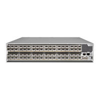
Juniper QFX10002 Manuals
Manuals and User Guides for Juniper QFX10002. We have
4
Juniper QFX10002 manuals available for free PDF download: Hardware Manual, Quick Start Manual
Juniper QFX10002 Hardware Manual (180 pages)
Brand:
Juniper
| Category:
Switch
| Size: 6.58 MB
Table of Contents
Table of Contents
3
About the Documentation
13
Documentation and Release Notes
13
Using the Examples in this Manual
13
Merging a Full Example
14
Merging a Snippet
14
About the Documentation
15
Documentation Conventions
15
Table 1: Notice Icons
15
Table 2: Text and Syntax Conventions
16
Documentation Feedback
17
Requesting Technical Support
17
Creating a Service Request with JTAC
18
Self-Help Online Tools and Resources
18
Overview
19
QFX10002 Switch Description
19
QFX10002 System Overview
19
Benefits of the QFX10002 Switch
20
Figure 1: QFX10002-36Q Port Panel
20
QFX10002 Models
20
Figure 2: QFX10002-72Q Port Panel
21
Figure 3: QFX10002-60C Port Panel
21
Table 3: QFX10002 Switch Product Numbers
21
Cooling and Power
22
System Architecture
22
Table 4: Port Capacities
22
Figure 4: QFX10002 FRU Panel
23
QFX10002 Hardware Component Overview
23
System Software
23
QFX10002 Component Redundancy
24
Table 5: QFX10002 Hardware Components
24
Table 6: Available Power Redundancy Options
25
QFX10002 Field-Replaceable Units
26
Table 7: Frus in a QFX10002 Device
26
Figure 5: QFX10002-36Q FRU Panel
27
Overview
27
QFX10002 Port Panels
27
QFX10002-36Q Port Panel
27
Figure 6: QFX10002-36Q Port Panel
28
Overview
28
Table 8: QFX10002-36Q Port Capacities
28
100-Gbps Operation and Configuration
29
Network Ports
29
40-Gbps Channelization
30
Figure 7: All Ports Are 40-Gigabit Ethernet by Default
30
Figure 8: 100-Gigabit Ethernet Ports Are Indicated by a Black Line Underneath
30
Figure 9: 100-Gigabit Ethernet Port Disables Two Associated 40-Gigabit Ethernet
30
The Port
30
Figure 10: Use the First and Fourth Port in each 6XQSFP Cage to Channelize a
31
Port Mapping
31
Table 9: QFX10002-36Q Port Mapping
31
Figure 11: QFX10002-60C Port Panel
33
Network Ports
33
Overview
33
QFX10002-60C Port Panel
33
Table 10: QFX10002-60 Port Capacities
33
Channelization
34
Table 11: Maximum Port Configuration
34
Table 12: Port Mapping for Channelization
34
Overview
35
QFX10002-72Q Port Panel
35
Figure 12: QFX10002-72Q Port Panel
36
Switch Ports
36
Table 13: QFX10002-72Q Port Capacities
36
100-Gbps Operation and Configuration
37
40-Gbps Channelization
38
Figure 13: All Ports Are 40-Gigabit Ethernet by Default
38
Figure 14: 100-Gigabit Ethernet Ports Are Indicated by a Black Line Underneath
38
Figure 15: 100-Gigabit Ethernet Port Disables Two Associated 40-Gigabit Ethernet Ports in the Port Group
38
Figure 16: Use the First and Fourth Port in each 6XQSFP Cage to Channelize a
39
Port Mapping
39
Table 14: QFX10002-72Q Port Mapping
39
Figure 17: Port Leds
42
QFX10002 Network Port Leds
42
Table 15: Network Port Leds on QSFP+ Ports on a QFX10002
43
Figure 18: QFX10002-72Q Port Panel and Management Panel
44
QFX10002 Management Panel
44
Figure 19: QFX10002-36Q Port Panel and Management Panel
45
Figure 20: QFX10002-60C Port Panel and Management Panel
45
Figure 21: QFX10002 Management Panel Components
46
QFX10002 Management Port Leds
46
Figure 22: Management Port Leds on a QFX10002 Switch
47
QFX10002 Chassis Status Leds
47
Table 16: Management Port Leds on a QFX10002 Switch
47
Figure 23: Chassis Status Leds on QFX10002 Models
48
Table 17: Chassis Status Leds on a QFX10002 Switch
48
Fan Modules
51
Figure 24: Fan Module for the QFX10002-72Q and QFX10002-36Q
51
QFX10002 Cooling System
51
QFX10002 Cooling System Description and Airflow
51
Figure 25: Fan Module for the QFX10002-60C
52
Table 18: Fan Modules in the QFX10002
52
Fan Module Status
53
Figure 26: Air out Airflow through the QFX10002-72Q and QFX10002-36Q
53
Figure 27: Air out Airflow through the QFX10002-60C Chassis
53
Figure 28: Fan Module LED in a QFX10002
54
QFX10002 Fan Module LED
54
Table 19: Fan Module Status LED
54
QFX10002 AC Power Supply Description
55
QFX10002 Power System
55
Table 20: QFX10002 Fan Module LED
55
Figure 29: 1600-W AC Power Supply in a QFX10002 Models
56
QFX10002 AC Power Specifications
56
Table 21: QFX10002 AC Power Supply
56
Table 22: AC Power Specifications for a QFX10002
56
AC Power Cord Specifications for a QFX Series Device
57
QFX10002 DC Power Supply Description
58
Table 23: AC Power Cord Specifications
58
Figure 30: DC Power Supply in QFX10002 Models
59
QFX10002 DC Power Specifications
59
Table 24: QFX10002 DC Power Supply
59
Table 25: DC Power Specifications for a QFX10002
59
QFX10002 DC Power Cable Specifications
60
Table 26: QFX10002 DC Power Cable Specifications
60
QFX10002 Power Supply LED
61
Figure 31: AC Power Supply LED
62
Figure 32: DC Power Supply LED
62
Table 27: Power Supply Leds on a QFX10002 Switch
62
Chapter 2 Site Planning, Preparation, and Specifications
65
QFX10002 Site Preparation Checklist
65
Site Planning, Preparation, and Specifications
65
Table 28: Site Preparation Checklist
65
QFX10002 Site Guidelines and Requirements
66
QFX10002 Environmental Requirements and Specifications
67
Table 29: QFX10002 Environmental Tolerances
67
General Site Guidelines
68
QFX10002 Chassis Grounding Cable and Lug Specifications
68
QFX10002 Clearance Requirements for Airflow and Hardware Maintenance
69
QFX10002 Chassis Physical Specifications
70
QFX5120 Site Electrical Wiring Guidelines
70
Table 30: Physical Specifications for the QFX10002
70
QFX10002 Rack Requirements
71
Table 31: Site Electrical Wiring Guidelines
71
Table 32: Rack Requirements for the QFX10002
71
QFX10002 Cabinet Requirements
72
Table 33: Cabinet Requirements for the QFX10002
72
QFX10002 Network Cable and Transceiver Planning
73
Determining Transceiver Support for the QFX10002
73
Cable Specifications for QSFP+ and QSFP28 Transceivers
74
Table 34: QSFP+ and QSFP28 Optical Module Receptacle Pinouts
74
Table 35: QSFP+ MPO Fiber-Optic Crossover Cable Pinouts
75
Dispersion
76
Signal Loss in Multimode and Single-Mode Fiber-Optic Cables
76
Attenuation and Dispersion in Fiber-Optic Cable
76
Calculating Power Budget and Power Margin for Fiber-Optic Cables
77
Calculating Power Budget for Fiber-Optic Cable
77
Calculating Power Margin for Fiber-Optic Cable
78
Table 36: Estimated Values for Factors Causing Link Loss
78
QFX10002 Management Cable Specifications and Pinouts
79
QFX Series
79
RJ-45 Management Port Connector Pinout Information
80
Console Port Connector Pinout Information
80
Table 37: Cable Specifications for Console and Management Connections for the QFX Series
80
Table 38: RJ-45 Management Port Connector Pinout Information
80
RJ-45 to DB-9 Serial Port Adapter Pinout Information
81
Table 39: Console Port Connector Pinout Information
81
Table 40: RJ-45 to DB-9 Serial Port Adapter Pinout Information
81
RJ-45 Port, QSFP+ Port, QSFP28 Port, SFP+ Port, and SFP Port Connector Pinout Information
82
Table 41: 10/100/1000BASE-T Ethernet Network Port Connector Pinout Information for EX4300 Switches Except EX4300-48MP and EX4300-48MP-S Switches
82
Table 42: 10/100/1000BASE-T Ethernet Network Port and 100/1000/2500/5000/10000BASE-T Ethernet Network Port Connector Pinout Information for EX4300-48MP and EX4300-48MP-S Switches
83
Table 43: SFP Network Port Connector Pinout Information
84
Table 44: SFP+ Network Port Connector Pinout Information
84
Table 45: QSFP+ and QSFP28 Network Port Connector Pinout Information
85
USB Port Specifications for the QFX Series
87
Initial Installation and Configuration
89
QFX10002 Installation Overview
89
Overview of Installing the QFX10002
89
QFX10002 Installation Safety Guidelines
90
General Installation Safety Guidelines
90
QFX10002 Chassis Lifting Guidelines
90
Unpacking and Mounting the QFX10002
91
Unpacking a QFX10002
91
Mounting a QFX10002 in a Rack
92
Table 46: Inventory of Components Supplied with a QFX10002
92
Before You Begin Rack Installation
93
Four Post Procedure
94
Figure 34: Removing the Screws Holding the Cover
95
Figure 35: Attaching Mounting Rails to the QFX10002 Switch Chassis
95
Connecting the QFX10002
96
Figure 36: Attach Switch to Rack
96
Connecting the QFX10002 to Ground
97
Connecting a QFX10002 to a Management Ethernet Device
98
Figure 37: Connecting a Grounding Cable to the QFX10002
98
Connecting a QFX Series Device to a Management Console
99
Figure 38: Connecting a QFX10002 to a Network for Out-Of-Band
99
Connecting AC Power to a QFX10002
100
Figure 39: Connecting the QFX Series to a Management Console through a
100
Figure 40: Connecting the QFX Series Directly to a Management Console
100
Figure 41: Connecting an AC Power Cord to an AC Power Supply in a
101
Connecting DC Power to a QFX10002
102
Figure 42: Connecting a Straight DC Power Cable to a DC Power Supply (CBL-JNP-PWR-DSUB)
104
Figure 43: Connecting a Right-Angle DC Power Cable to a DC Power Supply (CBL-JNP-PWR-DSUB2)
104
Figure 44: Connecting a Right-Angle DC Power Cable to a DC Power Supply (CBL-JNP-PWR-DSUB3)
105
Registering Products-Mandatory for Validating Slas
106
Configuring a QFX10000
106
Maintaining Components
109
Installing and Removing QFX10002 Hardware Components
109
Maintaining QFX10002 Cooling System Components
110
Removing a Fan Module from a QFX10002
110
Installing a Fan Module in a QFX10002
111
Figure 45: Removing a Fan Module from QFX10002 Models
111
Figure 46: Installing a Fan Module in a QFX10002-36Q or QFX10002-72Q
112
Maintaining QFX10002 Power Supplies
113
Removing a Power Supply from a QFX10002
113
Figure 47: Installing a Fan Module in a QFX10002-60C
113
Figure 48: Removing a Power Supply from a QFX10002-72Q
114
Installing a Power Supply in a QFX10002
115
Figure 49: Inserting a Power Supply Blank Cover
115
Figure 50: Removing a Power Supply Blank Cover
116
Figure 51: Installing a Power Supply in a QFX10002-72Q
116
Maintaining Transceivers and Fiber-Optic Cables on QFX10002
117
Removing a Transceiver
117
Figure 52: Removing an SFP, SFP+, XFP, or a QSFP+ Transceiver
119
Installing a Transceiver
120
Disconnecting a Fiber-Optic Cable
122
Figure 53: Installing a Transceiver
122
Connecting a Fiber-Optic Cable
123
Maintaining Fiber-Optic Cables
123
Figure 54: Connecting a Fiber-Optic Cable to an Optical Transceiver Installed in
123
Rebooting or Powering off a QFX10002
124
Rebooting a QFX10002
124
Powering off a QFX10002
125
Removing a QFX10002 from a Rack
127
Troubleshooting
129
Troubleshooting QFX10002 Components
129
QFX10002 Troubleshooting Resources Overview
129
QFX Series Alarm Messages Overview
130
Chassis Alarm Messages on QFX10002 Switches
130
Table 47: QFX10002 Chassis Alarm Messages
131
Components
135
Contacting Customer Support
135
Returning the Chassis or Components
136
Locating the Serial Number on a QFX10002 or Component
136
Listing the Chassis and Component Details Using the CLI
136
Switch
137
Locating the Serial Number ID Labels on FRU Components
137
Removing the Solid State Drives for RMA
137
Figure 55: Removing or Replacing Flat-Head Screws in the Access Door
138
Figure 56: Remove or Replacing the Thumb-Screw Fasteners
139
Figure 57: Removing the Ssds
139
Returning a QFX10002 or Component for Repair or Replacement
140
Packing a QFX10002 or Component for Shipping
140
Packing a QFX10002 Switch for Shipping
141
Packing QFX10002 Switch Components for Shipping
142
Safety and Compliance Information
143
General Safety Guidelines and Warnings
144
Definitions of Safety Warning Levels
145
Qualified Personnel Warning
146
Warning Statement for Norway and Sweden
147
Fire Safety Requirements
147
Fire Suppression
147
Fire Suppression Equipment
147
Installation Instructions Warning
148
Chassis and Component Lifting Guidelines
149
Restricted Access Warning
149
Ramp Warning
150
Rack-Mounting and Cabinet-Mounting Warnings
151
Grounded Equipment Warning
155
Laser and LED Safety Guidelines and Warnings
155
General Laser Safety Guidelines
156
Class 1 Laser Product Warning
156
Class 1 LED Product Warning
156
Laser Beam Warning
157
Radiation from Open Port Apertures Warning
157
Maintenance and Operational Safety Guidelines and Warnings
158
Battery Handling Warning
159
Jewelry Removal Warning
160
Lightning Activity Warning
161
Operating Temperature Warning
161
Product Disposal Warning
163
General Electrical Safety Guidelines and Warnings
163
Action to Take after an Electrical Accident
164
Prevention of Electrostatic Discharge Damage
165
Figure 58: Placing a Component into an Antistatic Bag
165
AC Power Electrical Safety Guidelines
166
AC Power Disconnection Warning
167
DC Power Electrical Safety Guidelines
167
DC Power Copper Conductors Warning
168
DC Power Disconnection Warning
168
DC Power Grounding Requirements and Warning
170
DC Power Wiring Sequence Warning
171
DC Power Wiring Terminations Warning
172
Multiple Power Supplies Disconnection Warning
173
TN Power Warning
174
Agency Approvals and Compliance Statements for the QFX10002
175
Agency Approvals for the QFX Series
175
Compliance Statements for EMC Requirements for the QFX Series
176
Canada
176
European Community
177
Israel
177
Japan
177
Korea
178
Tawain
178
United States
178
Nonregulatory Environmental Standards
178
Compliance Statements for Acoustic Noise for the QFX Series
179
Advertisement
Juniper QFX10002 Hardware Manual (215 pages)
Brand:
Juniper
| Category:
Switch
| Size: 4.97 MB
Table of Contents
Table of Contents
3
About this Guide
9
Overview
10
QFX10002 System Overview
11
QFX10002 Switch Description
11
QFX10002 Hardware Component Overview
16
QFX10002 Component Redundancy
17
QFX10002 Field-Replaceable Units
20
QFX10002 Port Panels
21
QFX10002-36Q Port Panel
21
QFX10002-60C Port Panel
29
QFX10002-72Q Port Panel
33
QFX10002 Network Port Leds
42
QFX10002 Management Panel
44
QFX10002 Management Port Leds
48
QFX10002 Chassis Status Leds
49
QFX10002 Cooling System
54
QFX10002 Cooling System and Airflow
54
QFX10002 Fan Module LED
58
QFX10002 Power System
59
QFX10002 AC Power Supply Description
60
QFX10002 AC Power Specifications
61
AC Power Cord Specifications for QFX10002 Switches
62
QFX10002 DC Power Supply Description
65
QFX10002 DC Power Specifications
66
QFX10002 DC Power Cable Specifications
67
QFX10002 Power Supply LED
69
Site Planning, Preparation, and Specifications
72
QFX10002 Site Preparation Checklist
73
QFX10002 Site Guidelines and Requirements
75
QFX10002 Environmental Requirements and Specifications
75
General Site Guidelines
77
QFX10002 Chassis Grounding Cable and Lug Specifications
77
QFX10002 Clearance Requirements for Airflow and Hardware Maintenance
78
QFX10002 Chassis Physical Specifications
79
Site Electrical Wiring Guidelines
80
QFX10002 Rack Requirements
81
QFX10002 Cabinet Requirements
83
QFX10002 Network Cable and Transceiver Planning
85
Determining Transceiver Support for the QFX10002
85
Cable Specifications for QSFP+ and QSFP28 Transceivers
86
Understanding QFX Series Fiber-Optic Cable Signal Loss, Attenuation, and Dispersion
88
Calculating Power Budget and Power Margin for Fiber-Optic Cables
90
How to Calculate Power Budget for Fiber-Optic Cables
90
How to Calculate Power Margin for Fiber-Optic Cables
91
QFX10002 Management Cable Specifications and Pinouts
93
Cable Specifications for Console and Management Connections for the QFX Series
93
RJ-45 Management Port Connector Pinout Information
94
Console Port Connector Pinout Information
95
RJ-45 to DB-9 Serial Port Adapter Pinout Information
96
Port, SFP Port, SFP+ Port, QSFP+ Port, and QSFP28 Port Connector Pinout Information
96
USB Port Specifications for the QFX Series
103
Initial Installation and Configuration
105
QFX10002 Installation Overview
106
Overview of Installing the QFX10002
106
QFX10002 Installation Safety Guidelines
107
Unpacking and Mounting the QFX10002
108
Unpacking a QFX10002
108
Mounting a QFX10002 in a Rack
110
Before You Begin Rack Installation
110
Four Post Procedure
112
Connecting the QFX10002
114
Connecting the QFX10002 to Ground
114
In this Section
114
Connecting a QFX10002 to a Management Ethernet Device
117
Qfx10000
117
Connecting a QFX Series Device to a Management Console
118
Connecting AC Power to a QFX10002
119
Connecting DC Power to a QFX10002
120
Register Products-Mandatory to Validate Slas
125
Performing an Initial Configuration of a QFX10000
125
Maintaining Components
129
Installing and Removing QFX10002 Hardware Components
130
Maintaining QFX10002 Cooling System Components
131
Removing a Fan Module from a QFX10002
131
Installing a Fan Module in a QFX10002
133
Maintaining QFX10002 Power Supplies
135
Removing a Power Supply from a QFX10002
135
Installing a Power Supply in a QFX10002
137
Maintaining Transceivers and Fiber-Optic Cables on QFX10002
139
Remove a Transceiver
139
Install a Transceiver
142
Disconnect a Fiber-Optic Cable
145
Connect a Fiber-Optic Cable
146
How to Handle Fiber-Optic Cables
146
Rebooting or Powering off a QFX10002
147
Rebooting a QFX10002
148
Powering off a QFX10002
148
Removing a QFX10002 from a Rack
151
Troubleshooting
153
Troubleshooting QFX10002 Components
154
QFX10002 Troubleshooting Resources Overview
154
QFX Series Alarm Messages Overview
155
Chassis Alarm Messages on QFX10002 Switches
155
Contacting Customer Support and Returning the Chassis or Components
160
Contact Customer Support
161
Returning the Chassis or Components
162
Locating the Serial Number on a QFX10002 or Component
162
Listing the Chassis and Component Details Using the CLI
163
Locating the Chassis Serial Number ID Label on a QFX10002 Switch
164
Locating the Serial Number ID Labels on FRU Components
164
Removing the Solid State Drives for RMA
164
Returning a QFX10002 or Component for Repair or Replacement
167
Packing a QFX10002 or Component for Shipping
168
Packing a QFX10002 Switch for Shipping
169
Packing QFX10002 Switch Components for Shipping
169
Safety and Compliance Information
171
General Safety Guidelines and Warnings
173
Definitions of Safety Warning Levels
174
Qualified Personnel Warning
176
Warning Statement for Norway and Sweden
176
Fire Safety Requirements
177
Installation Instructions Warning
178
Chassis and Component Lifting Guidelines
179
Restricted Access Warning
179
Ramp Warning
181
Rack-Mounting and Cabinet-Mounting Warnings
181
Grounded Equipment Warning
185
Laser and LED Safety Guidelines and Warnings
186
Radiation from Open Port Apertures Warning
189
Maintenance and Operational Safety Guidelines and Warnings
190
General Electrical Safety Guidelines and Warnings
196
Action to Take after an Electrical Accident
197
Prevention of Electrostatic Discharge Damage
198
AC Power Electrical Safety Guidelines
199
AC Power Disconnection Warning
200
DC Power Electrical Safety Guidelines
201
DC Power Copper Conductors Warning
202
DC Power Disconnection Warning
203
DC Power Grounding Requirements and Warning
204
DC Power Wiring Sequence Warning
205
DC Power Wiring Terminations Warning
206
Multiple Power Supplies Disconnection Warning
208
TN Power Warning
209
Agency Approvals and Compliance Statements for the QFX10002
209
Juniper QFX10002 Quick Start Manual (7 pages)
Brand:
Juniper
| Category:
Switch
| Size: 1.01 MB
Table of Contents
Step 2: up and Running
4
Set Parameter Values
4
Perform the Initial Configuration
4
Safety Warnings Summary
6
Power Cable Warning (Japanese)
7
Contacting Juniper Networks
7
Advertisement
Juniper QFX10002 Quick Start Manual (2 pages)
Brand:
Juniper
| Category:
Network Router
| Size: 0.57 MB
Advertisement
Related Products
Juniper QFX10016
Juniper QFX5100
Juniper QFX5100-48SH
Juniper QFX5100-48TH
Juniper QFX10002-36Q
Juniper QFX10002-72Q
Juniper QFX10008
Juniper QFX10002-60C
Juniper QFX5230-64CD
Juniper QFX3000
Juniper Categories
Network Router
Switch
Gateway
Software
Network Hardware
More Juniper Manuals
Login
Sign In
OR
Sign in with Facebook
Sign in with Google
Upload manual
Upload from disk
Upload from URL