Table of Contents
Advertisement
Quick Links
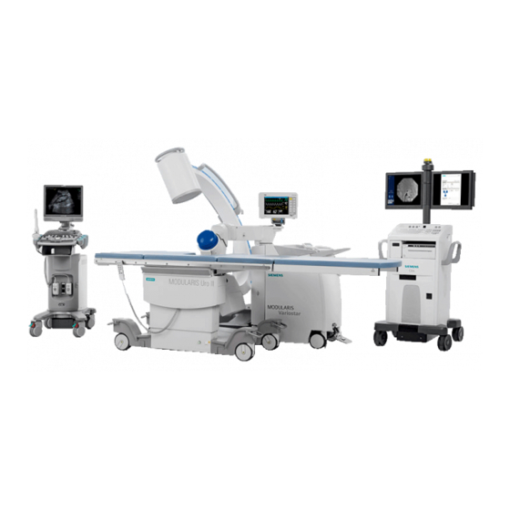
MODULARIS Uro Plus
Service Instructions
LITHOSTAR MODULARIS
Print No.: SPL1-130.840.02.03.02
Replaces: SPL1-130.840.02.02.02
SP
© Siemens AG 2004
The reproduction, transmission or use
of this document or its contents is not
permitted
without express written
authority. Offenders will be liable for
damages. All rights, including rights
created by patent grant or registration
of a utility model or design are
reserved.
English
Doc. Gen. Date:
04.05
Advertisement
Table of Contents

Related Manuals for Siemens MODULARIS Uro Plus


Summary of Contents for Siemens MODULARIS Uro Plus
- Page 1 MODULARIS Uro Plus Service Instructions LITHOSTAR MODULARIS © Siemens AG 2004 The reproduction, transmission or use of this document or its contents is not permitted without express written authority. Offenders will be liable for damages. All rights, including rights created by patent grant or registration of a utility model or design are reserved.
- Page 2 Assemblers and other persons who are not employed by or otherwise directly affiliated with or autho- rized by Siemens or one of its affiliates are directed to contact one of the local offices of Siemens or one of its affiliates before attempting installation or service procedures.
-
Page 3: Table Of Contents
"Chip card invalid" ....... . . 2 - 13 LITHOSTAR MODULARIS SIEMENS ..... . . 2 - 13 Missing Iso-center cross on the ultrasound system . - Page 4 Curved Probe ........4 - 33 MODULARIS Uro Plus SPL1-130.840.02...
- Page 5 Readout the Software Version Adara ......8 - 7 9 _______Changes to the previous version__________________________________ 9 - 1 Siemens AG SPL1-130.840.02 Page 5 of 6 MODULARIS Uro Plus Medical Solutions Rev. 03 04.05 CS PS 24...
- Page 6 0 - 6 Table of Contents Page MODULARIS Uro Plus SPL1-130.840.02 Page 6 of 6 Siemens AG Rev. 03 04.05 CS PS 24 Medical Solutions...
-
Page 7: Safety Information And Protective Measures
In the event that there are no existing local regulations, the following provisions should be adhered to in the interest of the safety of customers, patients, employees and third parties as well as the company. Siemens AG SPL1-130.840.02 Page 1 of 2 MODULARIS Uro Plus Medical Solutions Rev. 03 04.05 CS PS 24... -
Page 8: Tools And Measurement Devices Required
If the line voltage or the line frequency on-site deviates from the information indicated upon delivery of the Modularis Uro Plus, the values given are invalid. The values should be marked invalid (crossed out with the comment "invalid values" and the service engi- neer should sign and date this copy). -
Page 9: Info, E00 And E99
Is water running out of the hoses and hose connections? cause/action: Air in the cooling system? Check the fill level in the cooling circuit. Siemens AG SPL1-130.840.02 Page 1 of 14 MODULARIS Uro Plus Medical Solutions Rev. 03 04.05 CS PS 24... -
Page 10: Water System, E14 - E15
Error Text: X-ray button on the control unit activated with switch on. Possible X-ray button stuck? cause/action: Control unit o.k.? Cable o.k.? MODULARIS Uro Plus SPL1-130.840.02 Page 2 of 14 Siemens AG Rev. 03 04.05 CS PS 24 Medical Solutions... -
Page 11: Controls, E22 - E25
Check the setting of the SIREMOBIL angulation brake (see E23) Error Text: C-arm potentiometer not working. Possible Potentiometer connected? cause/action: Check plug D3.X30! Connect the cable to the potentiometer. Siemens AG SPL1-130.840.02 Page 3 of 14 MODULARIS Uro Plus Medical Solutions Rev. 03 04.05 CS PS 24... -
Page 12: Controls, E26 - E29
Check the setting of the SIREMOBIL angulation brake (see E23). Error Text: Shock wave release button sticks. Possible Check control unit. Circuit diagram J1048 – 25. cause/action: MODULARIS Uro Plus SPL1-130.840.02 Page 4 of 14 Siemens AG Rev. 03 04.05 CS PS 24... -
Page 13: Monitoring, E31 - E34
Possible Connection cable D3.X2 o.k.? cause/action: Board D3? Read out the temperature with the service PC. Refer also to error 45. Siemens AG SPL1-130.840.02 Page 5 of 14 MODULARIS Uro Plus Medical Solutions Rev. 03 04.05 CS PS 24... -
Page 14: Monitoring, E40 - E48
Check valve (coupling circuit). Check card terminal. Error Text: Reference for temperature sensors defective. Possible Replace temperature sensors. cause/action: Replace board D3. MODULARIS Uro Plus SPL1-130.840.02 Page 6 of 14 Siemens AG Rev. 03 04.05 CS PS 24 Medical Solutions... - Page 15 Clock stopped (this message is also displayed when the battery is replaced) Possible Connection cable D3.X31 - XP7 present under the cover? cause/action: Set the clock! Siemens AG SPL1-130.840.02 Page 7 of 14 MODULARIS Uro Plus Medical Solutions Rev. 03 04.05 CS PS 24...
-
Page 16: High Voltage Circuit, E60 - E67
Error Text: No ignition of spark gap after trigger pulse (several times). Possible Check the fiber optic cable! cause/action: Replace the charging/ energy unit! MODULARIS Uro Plus SPL1-130.840.02 Page 8 of 14 Siemens AG Rev. 03 04.05 CS PS 24... -
Page 17: High Voltage Circuit, E68 - E74
- Disconnect the fiber optic cable on both ends and check by holding it up to the light - place it on the Clk (U5) of board D3 and check whether light is visible. Siemens AG SPL1-130.840.02 Page 9 of 14 MODULARIS Uro Plus Medical Solutions Rev. 03 04.05 CS PS 24... -
Page 18: High Voltage Circuit, E75 - E78
- Disconnect the fiber optic cable on both ends and check by holding it up to the light - place it on the Clk (U5) of board D3 and check whether light is visible. MODULARIS Uro Plus SPL1-130.840.02 Page 10 of 14 Siemens AG Rev. -
Page 19: Internal Errors, E80 - E89
Appears each time a reset is done with switch S3 on board D3. This error may occur if the system is switched off during initiali- zation. Siemens AG SPL1-130.840.02 Page 11 of 14 MODULARIS Uro Plus Medical Solutions Rev. 03 04.05 CS PS 24... -
Page 20: Ultrasound, E90 - E93
Error Text: Erroneous US values. Possible C-MOS has lost values. Perform potentiometer adjustment cause/action: (Point "U" in the service menu). Check default values (see SPL1-130.038.01...). MODULARIS Uro Plus SPL1-130.840.02 Page 12 of 14 Siemens AG Rev. 03 04.05 CS PS 24... -
Page 21: Displays On Board D3
Missing Iso-center cross on the ultrasound system There is no communication between the ultrasound system and the LITHOSTAR MODULARIS. Siemens AG SPL1-130.840.02 Page 13 of 14 MODULARIS Uro Plus Medical Solutions Rev. 03 04.05 CS PS 24... - Page 22 2 - 14 LITHOSTAR MODULARIS Error List This page intentionally left blank. MODULARIS Uro Plus SPL1-130.840.02 Page 14 of 14 Siemens AG Rev. 03 04.05 CS PS 24 Medical Solutions...
-
Page 23: (Hyper) Terminal Program
In case of problems, use the Help function in the (Hyper) Terminal program. The font "Courier New" is recommended for reading data stored on the diskette. Siemens AG SPL1-130.840.02 Page 1 of 18 MODULARIS Uro Plus Medical Solutions Rev. 03 04.05 CS PS 24... -
Page 24: German Windows 95 / 98 / Nt
Basic procedure: open Windows Explorer. Open the folder, e.g. Temp, then click on the Datei menu and click "Neu / Textdatei". Enter the name for the text file. MODULARIS Uro Plus SPL1-130.840.02 Page 2 of 18 Siemens AG Rev. -
Page 25: English Windows 95 / 98 / Nt
Basic procedure: open Windows Explorer, open the folder e.g. Temp, then click on the "File" menu and click on New / Text file and enter the name for the text file. Siemens AG SPL1-130.840.02 Page 3 of 18 MODULARIS Uro Plus Medical Solutions Rev. 03 04.05 CS PS 24... -
Page 26: Working With The Terminal Program
MODULARIS, press the "h" key to display the following text: You will be notified if the software version is not compatible with the hardware version. Refer to document SPL1-130.038.01... (Intranet) for default values. --------------< SIEMENS LITHOSTAR MODULARIS >-------------- software version: V_ _ _ hardware:_ _ - _ _... -
Page 27: Select Option: H
Current voltage at the potentiometer for the US applicator. Accepta- ble deviation: 50. When US localisation is not available the value is 9995. Siemens AG SPL1-130.840.02 Page 5 of 18 MODULARIS Uro Plus Medical Solutions Rev. 03 04.05 CS PS 24... -
Page 28: Select Option: E
- The oldest error has the number 1; the most recent error is all the way at the top. - The line "last watchdog-error code" is internal information. - The errors can only be deleted in the system after all error numbers have been viewed. MODULARIS Uro Plus SPL1-130.840.02 Page 6 of 18 Siemens AG Rev. -
Page 29: Select Option: T
Entering "A" is only recommended for saving all data to a diskette. The data cannot be deleted until they have been read (on a workday). Selecting delete will erase all therapy data. Siemens AG SPL1-130.840.02 Page 7 of 18 MODULARIS Uro Plus Medical Solutions Rev. 03 04.05 CS PS 24... - Page 30 ! Once all of the therapy data for a day is listed, the above text will be displayed. Press the "d" key to delete all therapy data. MODULARIS Uro Plus SPL1-130.840.02 Page 8 of 18 Siemens AG Rev.
-
Page 31: Select Option: C
- *8: System shock wave counter value when card ejected Card in system - *7: Text: "Card locked to unit" - *8: .... Siemens AG SPL1-130.840.02 Page 9 of 18 MODULARIS Uro Plus Medical Solutions Rev. 03 04.05 CS PS 24... -
Page 32: Select Option: I
Push the probe receiver all the way to the front so that the space between the probe and the iso-center phantom is very small when the iso-center phantom is raised. • After pressing the "j" key, after "actual value: established value (max. 500) appears. MODULARIS Uro Plus SPL1-130.840.02 Page 10 of 18 Siemens AG Rev. - Page 33 ----------------------------------------- actual values change with key (-) (+) ----------------------------------------- threshold value = 100 mm scale low 7.7 % scale high 7.7 % Siemens AG SPL1-130.840.02 Page 11 of 18 MODULARIS Uro Plus Medical Solutions Rev. 03 04.05 CS PS 24...
-
Page 34: Select Option: R
Once the software download is complete, check that the values in the "ultrasound localiza- tion" menu for the applicators are identical to those in document SPL1-130.038.01.. (Intranet). If this is not the case, make the appropriate changes. MODULARIS Uro Plus SPL1-130.840.02 Page 12 of 18 Siemens AG Rev. -
Page 35: Software Download With Windows 95 / 98 / Nt
Check the system-specific settings (language, ECG triggering, pulse rate and table) Set the date and time. Check Ultrasound default values. For additional procedures, refer to pages 3-2 or 3-3 Siemens AG SPL1-130.840.02 Page 13 of 18 MODULARIS Uro Plus Medical Solutions Rev. 03 04.05 CS PS 24... - Page 36 Now: ------ ------ (X) = Physician's place for (X) : endourolog. therapy --------------- Left side version Right side version Fig. 3 MODULARIS Uro Plus SPL1-130.840.02 Page 14 of 18 Siemens AG Rev. 03 04.05 CS PS 24 Medical Solutions...
-
Page 37: Text After Replacing Board D3
Press 1 or 2 and follow the instructions. you selected: SIEMENS press 'C' to confirm, any other key to abort SIEMENS CAUTION This procedure cannot be undone. Siemens AG SPL1-130.840.02 Page 15 of 18 MODULARIS Uro Plus Medical Solutions Rev. 03 04.05 CS PS 24... -
Page 38: Lithostar Modularis Control Panel
R in se R in se B rig h tn e ss B rig h tn e ss S e rvice * with "pay per use" option only MODULARIS Uro Plus SPL1-130.840.02 Page 16 of 18 Siemens AG Rev. 03 04.05... - Page 39 S1 (Return) S1 (Return) S2 (reset) S2 (reset) S2 (reset) S1 (yes) S1 (yes) S1 (yes) S2 (no) S2 (no) S2 (no) Siemens AG SPL1-130.840.02 Page 17 of 18 MODULARIS Uro Plus Medical Solutions Rev. 03 04.05 CS PS 24...
- Page 40 3 - 18 Service software This page intentionally left blank. MODULARIS Uro Plus SPL1-130.840.02 Page 18 of 18 Siemens AG Rev. 03 04.05 CS PS 24 Medical Solutions...
-
Page 41: Lithostar Modularis Parts Overview
70 50 433 Refer to description SIREMOBIL switch 10 70 721 Refer to description Iso-center phantom 47 78 754 Refer to description Siemens AG SPL1-130.840.02 Page 1 of 34 MODULARIS Uro Plus Medical Solutions Rev. 03 04.05 CS PS 24... -
Page 42: Shock Wave Head
• If required, remove the 3 cover screws from both lower covers and remove the covers. • Reattach the covers in the reverse order after completion of all work. MODULARIS Uro Plus SPL1-130.840.02 Page 2 of 34 Siemens AG Rev. 03 04.05... -
Page 43: Removing The Shock Wave Head
- If the iso-center phantom has a serial number (2/Fig. 3) it can be removed by using two screw pulleys (1/Fig. 3) on the shock wave head. Siemens AG SPL1-130.840.02 Page 3 of 34 MODULARIS Uro Plus Medical Solutions Rev. 03 04.05 CS PS 24... - Page 44 Disconnect all the water hoses at both interfaces of the shock wave head. • Remove the shock wave head toward the front. NOTICE There may be water remaining in the shock wave head. MODULARIS Uro Plus SPL1-130.840.02 Page 4 of 34 Siemens AG Rev. 03 04.05...
-
Page 45: Installing The Shock Wave Head
Place the iso-center phantom on top so that it is flush and secure it with the four screws (V/Fig. 3) (use an Allen key with a guide pin for this purpose). Siemens AG SPL1-130.840.02 Page 5 of 34 MODULARIS Uro Plus Medical Solutions Rev. 03 04.05 CS PS 24... - Page 46 Release shock waves: both temperature values should increase closely in parallel (∆Τ < 3° C). • Reattach the system cover. • Perform a function test. MODULARIS Uro Plus SPL1-130.840.02 Page 6 of 34 Siemens AG Rev. 03 04.05 CS PS 24...
-
Page 47: Replace Isocenter Phantom
If an adjustment is necessary, it must be made via the shock wave head setting; refer to chapter "Iso-center with X-ray - to support arm serial number 0050". Siemens AG SPL1-130.840.02 Page 7 of 34 MODULARIS Uro Plus Medical Solutions Rev. 03 04.05 CS PS 24... -
Page 48: Cooling Unit
The ventilator and compressor in the cooling unit start up - if not, check the power supply - if o.k., replace cooling unit. • Switch the system off. • Reconnect both cables. MODULARIS Uro Plus SPL1-130.840.02 Page 8 of 34 Siemens AG Rev. 03 04.05... -
Page 49: Replacing The Cooling Unit
Adjust service switch S2 on board D3 to position 1 (service off). • Select "rinse" on the control unit and activate the cycle; this function ends automatically. Siemens AG SPL1-130.840.02 Page 9 of 34 MODULARIS Uro Plus Medical Solutions Rev. 03 04.05 CS PS 24... -
Page 50: Emptying The Cooling Circuit With The Old Pump (2/Fig. 10)
Activate the corresponding key for "empty" on the control unit until no more water flows. • Adjust service switch S2 on board D3 to position 1 (service off). • Switch the system off. MODULARIS Uro Plus SPL1-130.840.02 Page 10 of 34 Siemens AG Rev. 03 04.05... -
Page 51: Emptying The Cooling Circuit With The New Pump (3/Fig. 11)
Activate the corresponding key for "empty" (S6/Fig. 4/ page 3-16) on the control unit until the coupling bellows is located next to the lens. • Switch the system off. Siemens AG SPL1-130.840.02 Page 11 of 34 MODULARIS Uro Plus Medical Solutions Rev. 03 04.05 CS PS 24... -
Page 52: Hose Pump Head In The Coupling Circuit
Ensure that the hoses are the correct length, i.e. cut them to the same length as the old hoses. • Fill the cooling circuit (refer to the section "Filling the cooling circuit"). MODULARIS Uro Plus SPL1-130.840.02 Page 12 of 34 Siemens AG Rev. -
Page 53: Iwaki Cooling Pump
Connect the fasteners on the pump (The black-marked water hoses must be connected). • Fill the cooling circuit (refer to the section "Filling the cooling circuit"). Siemens AG SPL1-130.840.02 Page 13 of 34 MODULARIS Uro Plus Medical Solutions Rev. 03 04.05 CS PS 24... - Page 54 Reset the counter (refer to chapter 3). • Perform a function test. • Switch the system off and reattach the system cover. MODULARIS Uro Plus SPL1-130.840.02 Page 14 of 34 Siemens AG Rev. 03 04.05...
-
Page 55: High Voltage Connector
(Fig. 13). • Mount the shock wave head assembly (refer to the corresponding section). • Attach all covers (refer to the corresponding sections). Siemens AG SPL1-130.840.02 Page 15 of 34 MODULARIS Uro Plus Medical Solutions Rev. 03 04.05 CS PS 24... - Page 56 - If the "temperature sensor" cable is being replaced, the water supply from the defective one must be transferred to the new pressure sensor (for more information on this procedure, refer to the section "Air suction hose"). MODULARIS Uro Plus SPL1-130.840.02 Page 16 of 34 Siemens AG Rev.
- Page 57 Reattach the column cover. • Mount the shock wave head assembly (refer to the corresponding section). • Reattach all covers (refer to the corresponding section). Siemens AG SPL1-130.840.02 Page 17 of 34 MODULARIS Uro Plus Medical Solutions Rev. 03 04.05 CS PS 24...
-
Page 58: Air Suction Hose
Insulate the bracket connection of the water supply (F/Fig. 25) just removed, i.e. attach new teflon insulation tape with the screws; when doing this do not block the opening to the pressure sensor. MODULARIS Uro Plus SPL1-130.840.02 Page 18 of 34 Siemens AG Rev. -
Page 59: From Support Arm Serial Number 0051
Pierce the hose two times with a needle (approx. 1mm) in the same manner the old hose was pierced. • Reassemble in the opposite order.Ensure proper position of the Allen screws during reassembly. Siemens AG SPL1-130.840.02 Page 19 of 34 MODULARIS Uro Plus Medical Solutions Rev. 03 04.05 CS PS 24... -
Page 60: Board D3 Or Chip Card Reader
ECG triggering. • Reset switch S2 on board D3 to normal mode. • Turn system off and then on again. MODULARIS Uro Plus SPL1-130.840.02 Page 20 of 34 Siemens AG Rev. 03 04.05... -
Page 61: Board D3 Addition (Ultrasound)
The instructions for performing the pressure measurement are delivered with the shock wave pressure test device (PTU). • After completing the pressure measurement, restore the system to its previous status. Siemens AG SPL1-130.840.02 Page 21 of 34 MODULARIS Uro Plus Medical Solutions Rev. 03 04.05 CS PS 24... -
Page 62: Potentiometer For Angulation Drive
The potentiometer setting can also be checked with the Service PV (Chapter 3). • Tighten the toothed belt. • Perform C-arm adjustment as described on page 3- 10. • Reattach the covers. MODULARIS Uro Plus SPL1-130.840.02 Page 22 of 34 Siemens AG Rev. 03 04.05 CS PS 24... -
Page 63: Angulation Drive (C-Arm Drive)
Tighten the toothed belt. • Adjust the C-arm according to the description on pages 3 - 10. • Reattach the motor cover. Siemens AG SPL1-130.840.02 Page 23 of 34 MODULARIS Uro Plus Medical Solutions Rev. 03 04.05 CS PS 24... - Page 64 The lift switch-off in the SIREMOBIL Iso-C may not switch off if the floor is not level. If this is the case, make use of the additional steering castors (see also Operating Instructions). MODULARIS Uro Plus SPL1-130.840.02 Page 24 of 34 Siemens AG Rev.
- Page 65 - Tighten the plate (9/Fig. 29) with a torque of 18 Nm. - Tighten the plate (8/Fig. 29) with a torque of 10 Nm. Siemens AG SPL1-130.840.02 Page 25 of 34 MODULARIS Uro Plus Medical Solutions Rev. 03 04.05 CS PS 24...
-
Page 66: Adjusting Switches S1/S2
To support arm serial number 0050 - Remove the countersunk screw (9/Fig. 30). - Remove all screws from the covers. - Firmly pull the handle apart (10/Fig. 30). MODULARIS Uro Plus SPL1-130.840.02 Page 26 of 34 Siemens AG Rev. 03 04.05... - Page 67 - loosen the set screw (16/Fig. 33). - rotate the lever until the switch is activated. - tighten the set screw (16/Fig. 33). • Reattach the covers. Siemens AG SPL1-130.840.02 Page 27 of 34 MODULARIS Uro Plus Medical Solutions Rev. 03 04.05 CS PS 24...
-
Page 68: Balancing Spring For The Support Arm
- If the mount is different from the ones delivered, it must be replaced as well. - Be sure to have correct spacing (Fig. 36). • Reinstall the spring mount. MODULARIS Uro Plus SPL1-130.840.02 Page 28 of 34 Siemens AG Rev. - Page 69 - the air bubble can point to the right, but not to the left (Fig. 35). If the air bubble moves to the left side, the spring must be replaced. • Check the iso-center with radiation. Siemens AG SPL1-130.840.02 Page 29 of 34 MODULARIS Uro Plus Medical Solutions Rev. 03 04.05 CS PS 24...
-
Page 70: Support Arm Replacement
Push cables and hoses through the opening of the rotary joint and run them downwards. Refer to Fig. 23 for the cable run. Fasten the corrugated hose to the rotary joint (2/Fig. 23). MODULARIS Uro Plus SPL1-130.840.02 Page 30 of 34 Siemens AG Rev. - Page 71 (see Installation and Setting Instructions SPL 1-130.033.01 page 4-2). • Adjustment of the angulation motor (see page 4-23). • Check shot triggering and centering. • Attach all cover parts. Siemens AG SPL1-130.840.02 Page 31 of 34 MODULARIS Uro Plus Medical Solutions Rev. 03 04.05 CS PS 24...
-
Page 72: Replacement Of Rotary Joint Lock
Attach the sleeve on the new probe. Pay particular attention to the positioning, the marking (3/Fig. 40) and (4/Fig. 40) must form a line. • Tighten the 6 screws. • Check the ultrasound iso-center. MODULARIS Uro Plus SPL1-130.840.02 Page 32 of 34 Siemens AG Rev. 03 04.05... -
Page 73: Curved Probe
Tighten the 8 screws. • Check the ultrasound iso-center. Concluding work • Perform the protective conductor measurement. • Test all functions from the control panel. Siemens AG SPL1-130.840.02 Page 33 of 34 MODULARIS Uro Plus Medical Solutions Rev. 03 04.05 CS PS 24... - Page 74 4 - 34 LITHOSTAR MODULARIS This page intentionally left blank. MODULARIS Uro Plus SPL1-130.840.02 Page 34 of 34 Siemens AG Rev. 03 04.05 CS PS 24 Medical Solutions...
-
Page 75: Adjustment Procedure
SIREMOBIL Iso-C: 1. Camera rotation to 0°. 2. Deselect image reverse vertical (LED is off). 3. Deselect image reverse horizontal (LED off). Siemens AG SPL1-130.840.02 Page 1 of 8 MODULARIS Uro Plus Medical Solutions Rev. 03 04.05 CS PS 24... -
Page 76: Adjusting The 0° Position
Shift it with the screws (2/Fig. 2). Shift it with the screws (4/Fig. 2). Retighten the screws (1/Fig. 2) on Retighten the screws (3/Fig. 2) on both sides. both sides. MODULARIS Uro Plus SPL1-130.840.02 Page 2 of 8 Siemens AG Rev. 03 04.05... -
Page 77: Adjusting The 20° Position
The distance from the phantom to the center of the centering cross must be the same for both 20° positions (with a maximum deviation of ± 2 mm) (refer to C/Fig. 6). Siemens AG SPL1-130.840.02 Page 3 of 8 MODULARIS Uro Plus Medical Solutions Rev. 03 04.05 CS PS 24... -
Page 78: Concluding Work
SIREMOBIL Iso-C. - Tighten the screws (5/Fig. 4) on both sides. Concluding work • Perform the protective conductor measurement. • Perform a function check. MODULARIS Uro Plus SPL1-130.840.02 Page 4 of 8 Siemens AG Rev. 03 04.05 CS PS 24... -
Page 79: Adjustment Procedure
SIREMOBIL Iso-C: 1. Camera rotation to 0°. 2. Deselect image reverse vertical (LED is off). 3. Deselect image reverse horizontal (LED off). Siemens AG SPL1-130.840.02 Page 5 of 8 MODULARIS Uro Plus Medical Solutions Rev. 03 04.05 CS PS 24... -
Page 80: Adjusting The 0° Position
(refer to Fig. 8). - After adjusting the setting, retighten all screws. • If adjustment is not possible, adjust as for the support arm - serien no. < 0050. MODULARIS Uro Plus SPL1-130.840.02 Page 6 of 8 Siemens AG Rev. 03 04.05... -
Page 81: Concluding Work
SIREMOBIL Iso-C for column stop and reset if necessary. - Angulation motor - check adjustment. Concluding work • Perform the protective conductor measurement. • Perform a function check. Siemens AG SPL1-130.840.02 Page 7 of 8 MODULARIS Uro Plus Medical Solutions Rev. 03 04.05 CS PS 24... -
Page 82: Lithostar Modularis As "Lithoshare" Execution
Replace shock wave head -> adjustment of iso-center on the LITHOSTAR MODULARIS Replace switch in the SIREMOBIL Iso-C -> adjustment of iso-center on the SIREMOBIL Iso-C. MODULARIS Uro Plus SPL1-130.840.02 Page 8 of 8 Siemens AG Rev. 03 04.05... -
Page 83: Preparations
Plug in the lead (2/Fig. 1) and connect the probe to the ultrasound unit. • Make the line connection (marked orange) between LITHOSTAR MODULARIS and ultrasound unit. Siemens AG SPL1-130.840.02 Page 1 of 16 MODULARIS Uro Plus Medical Solutions Rev. 03 04.05 CS PS 24... -
Page 84: Checking The Target On The Sonoline G20
(2/Fig. 4). • If this is not the case, the adjustment process for the potentiometer in the ultrasound arm must be repeated or the ultrasound arm must be replaced. MODULARIS Uro Plus SPL1-130.840.02 Page 2 of 16 Siemens AG Rev. -
Page 85: Check Of Image Tilt
Push the probe so far forwards (3/Fig. 1) until the isocenter cross is approximately in the center of the SONOLINE Prima screen. • Press the menu key and display this. Siemens AG SPL1-130.840.02 Page 3 of 16 MODULARIS Uro Plus Medical Solutions Rev. 03 04.05 CS PS 24... - Page 86 • Check that the ultrasound arm is as shown in Fig. 1, if not align it. The longitudinal groove must be visible (1/Fig. 8). MODULARIS Uro Plus SPL1-130.840.02 Page 4 of 16 Siemens AG Rev. 03 04.05...
- Page 87 Press the key. • Move the cross with the trackball horizontally into the center of the white area on the isocenter phantom. Siemens AG SPL1-130.840.02 Page 5 of 16 MODULARIS Uro Plus Medical Solutions Rev. 03 04.05 CS PS 24...
- Page 88 With every probe check that the setting in this position is also in order. Make no changes to the image tilt setting. • After the check stow the parts in the corresponding transport cases. MODULARIS Uro Plus SPL1-130.840.02 Page 6 of 16 Siemens AG Rev.
- Page 89 153 ± 1 mm with default values, see SPL1-130.038.01 Array (2/Fig. 2) 151 ± 1 mm • Press the key ("Freeze" is deselected). Siemens AG SPL1-130.840.02 Page 7 of 16 MODULARIS Uro Plus Medical Solutions Rev. 03 04.05 CS PS 24...
- Page 90 "60" (D/Fig. 14). • Move the probe forward (3/Fig. 1) until the isocenter crosshair is approx. in the center of the SONOLINE Prima screen. MODULARIS Uro Plus SPL1-130.840.02 Page 8 of 16 Siemens AG Rev. 03 04.05...
- Page 91 ------- ------- Set trackball to DR (white background), 60 dB (E/Fig. 14) then actuate Dyn Rng Cam Din set value with control Siemens AG SPL1-130.840.02 Page 9 of 16 MODULARIS Uro Plus Medical Solutions Rev. 03 04.05 CS PS 24...
- Page 92 The value displayed for "D2" (H/Fig. 16) must be between 1 and 5 mm. This is only valid for the default values, see instructions, SPL1-130.038.01... • Press the key. MODULARIS Uro Plus SPL1-130.840.02 Page 10 of 16 Siemens AG Rev. 03 04.05...
- Page 93 For each probe, check whether the adjustment in this position is also okay. Do not make any change to the image tilt adjustment. • Following the check, store the parts in the appropriate transport cases. Siemens AG SPL1-130.840.02 Page 11 of 16 MODULARIS Uro Plus Medical Solutions Rev. 03 04.05 CS PS 24...
- Page 94 153 ± 1 mm with default values, see SPL1-130.038.01 Array (2/Fig. 2) 151 ± 1 mm • Press the key ("Freeze" is deselected). MODULARIS Uro Plus SPL1-130.840.02 Page 12 of 16 Siemens AG Rev. 03 04.05 CS PS 24 Medical Solutions...
- Page 95 "60" (D/Fig. 14). • Move the probe forward (3/Fig. 1) until the isocenter crosshair is approx. in the center of the SONOLINE Prima screen. Siemens AG SPL1-130.840.02 Page 13 of 16 MODULARIS Uro Plus Medical Solutions Rev. 03 04.05 CS PS 24...
- Page 96 Edge Côté Contorno then press Knob 60 (D/Fig. 21) ------- ------- ------- ------- Knob 60 dB (E/Fig. 21) Dyn Rng Cam Din MODULARIS Uro Plus SPL1-130.840.02 Page 14 of 16 Siemens AG Rev. 03 04.05 CS PS 24 Medical Solutions...
- Page 97 The value displayed for "D2" (H/Fig. 23) must be between 1 and 5 mm. This is only valid for the default values, see instructions, SPL1-130.038.01... • Press the key. Siemens AG SPL1-130.840.02 Page 15 of 16 MODULARIS Uro Plus Medical Solutions Rev. 03 04.05 CS PS 24...
- Page 98 For each probe, check whether the adjustment in this position is also okay. Do not make any change to the image tilt adjustment. • Following the check, store the parts in the appropriate transport cases. MODULARIS Uro Plus SPL1-130.840.02 Page 16 of 16 Siemens AG Rev.
-
Page 99: Standard Programming
Subtraction n.a. n.a. n.a. Landmark n.a. n.a. n.a. Video signal at document n.a. n.a. n.a. Image display n.a. n.a. n.a. Siemens AG SPL1-130.840.02 Page 1 of 2 MODULARIS Uro Plus Medical Solutions Rev. 03 04.05 CS PS 24... - Page 100 7 - 2 Memoskop Programming This page intentionally left blank. MODULARIS Uro Plus SPL1-130.840.02 Page 2 of 2 Siemens AG Rev. 03 04.05 CS PS 24 Medical Solutions...
-
Page 101: Selection Of The Modularis Cross On The Sonoline G20
Deselect the screen saver on the SONOLINE G20 (refer to the SONOLINE G20 operating instructions). • A cross (Fig. 1) is displayed when a probe is selected. Siemens AG SPL1-130.840.02 Page 1 of 8 MODULARIS Uro Plus Medical Solutions Rev. 03 04.05 CS PS 24... -
Page 102: Selection Of The Modularis Cross On The Sonoline Adara
• Deselect the screen saver on the SONOLINE Adara (refer to the SONOLINE Adara operating instructions). • A cross (Fig. 2) is displayed when a probe is selected. MODULARIS Uro Plus SPL1-130.840.02 Page 2 of 8 Siemens AG Rev. 03 04.05... - Page 103 Deselect the screen saver on the SONOLINE Adara (refer to the SONOLINE Adara operating instructions). • When a probe is selected, the following cross (Fig. 3) is displayed. Siemens AG SPL1-130.840.02 Page 3 of 8 MODULARIS Uro Plus Medical Solutions Rev. 03 04.05 CS PS 24...
-
Page 104: Label For Ultrasound Unit
(1/Fig. 4) (this label serves for identifying which ultrasound unit operates together with the LITHOSTAR MODULARIS). MUT MODULARIS The endoscopy trolley is started up by the manufacturer. Concluding work Refer to the "Concluding work" chapter. MODULARIS Uro Plus SPL1-130.840.02 Page 4 of 8 Siemens AG Rev. 03 04.05... -
Page 105: Overview Of Functions
Incl. imagen transd. sect mecanico Bildkippung Array Image Tilt Array _ _ *0.1° Setting the iso-center Basculement d’ image sondes conv. Inclinar imagen transductor curvo Siemens AG SPL1-130.840.02 Page 5 of 8 MODULARIS Uro Plus Medical Solutions Rev. 03 04.05 CS PS 24... - Page 106 IMP. default values download/reload. Paridad IMPAR Stop bit Stop bit Stop bit Stop bit ACK Codierung ACK Code Code ACK Codigo ACK MODULARIS Uro Plus SPL1-130.840.02 Page 6 of 8 Siemens AG Rev. 03 04.05 CS PS 24 Medical Solutions...
-
Page 107: Readout The Software Version G20
- Use capital letters to make entries, the key must only be used for the # symbol. - The entry is not visible on the monitor. Siemens AG SPL1-130.840.02 Page 7 of 8 MODULARIS Uro Plus Medical Solutions Rev. 03 04.05 CS PS 24... - Page 108 MUP Menu Ultrasound Device 8 - 8 This page intentionally left blank. Siemens AG SPL1-130.840.02 Page 8 of 8 MODULARIS Uro Plus Medical Solutions Rev. 03 04.05 CS PS 24...
- Page 109 - Under "German Windows 95 / 98 / NT": Stopbits changed to "1". - Under "English Windows 95 / 98 / NT": Stopbits changed to "1". Siemens AG SPL1-130.840.02 Page 1 of 2 MODULARIS Uro Plus Medical Solutions Rev. 03 04.05 CS PS 24...
- Page 110 9 - 2 Changes to the previous version This page intentionally left blank. MODULARIS Uro Plus SPL1-130.840.02 Page 2 of 2 Siemens AG Rev. 03 04.05 CS PS 24 Medical Solutions...