Sun Microsystems Ultra 1 Creator Series Service Manual
Hide thumbs
Also See for Ultra 1 Creator Series:
- Service manual (139 pages) ,
- Installation manual (61 pages) ,
- Upgrade manual (50 pages)
Table of Contents
Advertisement
Quick Links
Advertisement
Chapters
Table of Contents

Related Manuals for Sun Microsystems Ultra 1 Creator Series


Summary of Contents for Sun Microsystems Ultra 1 Creator Series
- Page 1 Ultra™ 1 Creator Series Service Manual Sun Microsystems, Inc. 901 San Antonio Road Palo Alto, CA 94303-4900 USA 650 960-1300 Fax 650 969-9131 Part No.: 802-4148-10 Revision A, August 1996 Send comments about this document to: docfeedback@sun.com...
- Page 2 FAR 52.227-19(6/87), or DFAR 252.227-7015(b)(6/95) and DFAR 227.7202-3(a). Sun, Sun Microsystems, the Sun logo, and Solaris are trademarks or registered trademarks of Sun Microsystems, Inc. in the United States and in other countries. All SPARC trademarks are used under license and are trademarks or registered trademarks of SPARC International, Inc. in the United States and in other countries.
-
Page 3: Table Of Contents
Contents Preface xv Product Description 1-1 Ultra 1 Series Overview 1-1 I/O Devices (Ultra 1 Creator Series Desktop) 1-3 Supported I/O Devices (Ultra 1 Creator Series Desktop) 1-4 1.3.1 System Unit Features 1-4 1.3.2 System Unit Components 1-5 SunVTS Overview 2-1 SunVTS Overview 2-1 2.1.1... - Page 4 Safety and Tool Requirements 5-1 Safety Requirements 5-1 Symbols 5-1 Safety Precautions 5-2 5.3.1 Modification to Equipment 5-2 5.3.2 Placement of a Sun Product 5-2 Power Cord Connection 5-3 5.4.1 Electrostatic Discharge 5-3 Ultra 1 Creator Series Service Manual • August 1996...
- Page 5 5.4.2 Lithium Battery 5-3 Tools Required 5-3 Power On and Off 6-1 Powering On the System 6-1 Powering Off the System 6-2 Internal Access 7-1 Removing the Cover 7-1 Attaching the Wrist Strap 7-2 Replacing the Cover 7-3 Major Subassemblies 8-1 Power Supply 8-1 8.1.1 Removing the Power Supply 8-1...
- Page 6 Removing an SBus Card 10-14 10.3.2 Replacing an SBus Card 10-16 10.3.3 Removing the SBus Card Adapter Bracket 10-17 10.4 FFB Card (Workstation Only) 10-19 10.4.1 Removing an FFB Card 10-19 Ultra 1 Creator Series Service Manual • August 1996...
- Page 7 10.4.2 Replacing an FFB Card 10-21 10.5 DSIMM 10-23 10.5.1 Removing a DSIMM 10-24 10.5.2 Replacing a DSIMM 10-26 10.6 System Board Fan 10-28 10.6.1 Removing the System Board Fan 10-28 10.6.2 Replacing the Board Fan 10-30 Replacement Parts 11-1 A.
- Page 8 Ultra 1 Creator Series Service Manual • August 1996...
- Page 9 Figures Ultra 1 Creator Series Desktop System 1-2 FIGURE 1-1 Ultra Enterprise 1 Server 1-2 FIGURE 1-2 System Unit Rear View 1-7 FIGURE 1-3 System Unit with Cover Removed 1-8 FIGURE 1-4 Sun Type-5 Keyboard 3-5 FIGURE 3-1 Power LED 3-12...
- Page 10 Replacing the Disk Drive 9-4 FIGURE 9-3 Replacing the EMI Door 9-5 FIGURE 9-4 Chassis Bracket 9-6 FIGURE 9-5 Placing the Chassis Bracket on Top of the Disk Drive 9-7 FIGURE 9-6 Ultra 1 Creator Series Service Manual • August 1996...
- Page 11 Connecting Cables to the CD-ROM Drive, 4-mm/8-mm Tape Drive, and Diskette Drive 9-8 FIGURE 9-7 Positioning the Chassis Bracket 9-9 FIGURE 9-8 Positioning the CD-ROM Drive or 4-mm/8-mm Tape Drive 9-11 FIGURE 9-9 Positioning the Diskette Drive 9-13 FIGURE 9-10 Positioning the Diskette Drive 9-14 FIGURE 9-11 DC Power Disconnection 10-3...
- Page 12 Graphics Card 13W3 Video Con B-21 FIGURE B-9 System Unit or Server Functional Block Diagram C-2 FIGURE C-1 Ultra 1 Creator Series System Board Block Diagram C-17 FIGURE C-2 Identifying Jumper Pins C-18 FIGURE C-3 Ultra 1 Creator Series Service Manual • August 1996...
- Page 13 Tables Supported I/0 Devices 1-3 TABLE 1-1 System Unit/Server Components TABLE 1-2 SunVTS Documentation 2-2 TABLE 2-1 Diag-Level Switch Settings 3-2 TABLE 3-1 Keyboard LED Patterns 3-13 TABLE 3-2 Internal Drives Identification 4-3 TABLE 4-1 Connector 2601 Pin Description TABLE 4-2 Connector 2603 Pin Description TABLE 4-3 DSIMM Physical Memory Address...
- Page 14 Audio Specifications C-10 TABLE C-3 Built-In Speaker Specifications C-10 TABLE C-4 Ultra 1 Creator Series Desktop Workstation and Ultra Enterprise 1 Server Power Supply TABLE C-5 Budget C-16 Serial Port Jumper Settings C-18 TABLE C-6 Flash PROM Jumper Settings C-19...
-
Page 15: Preface
Chapter Number/Title Content Description Part 1, “System Chapter 1, “Product Describes the major components Information” Description” of the Ultra 1 Creator series desktop system and the Ultra Enterprise 1 server Part 2, Chapter 2, “SunVTS Describes the execution of “Troubleshooting”... - Page 16 Glossary, and Index” signal descriptions, and functional descriptions for the Ultra 1 Creator series, respectively Glossary Provides a listing of acronyms, terms, and definitions Index Provides a quick reference to specific topics Ultra 1 Creator Series Service Manual • August 1996...
- Page 17 Only people who have been trained by the Sun Microsystems training facilities (or by Sun Microsystems affiliates) and have been certified as required by local and national laws are considered qualified. Note – Prior to performing service or repair, carefully read the associated procedure.
- Page 18 1 Creator Series Internal Storage 802-4151 Device User’s Guide ‰ ‰ Configuration Ultra 1 Creator Series Reference Manual 802-4147 Specification 17-Inch Entry, 17-Inch Premium, and 20-Inch 802-6168 Premium Color Monitors Specifications xviii Ultra 1 Creator Series Service Manual • August 1996...
- Page 19 Related Documents (Continued) TABLE P-3 Application Title Part Number ™ Specification SunCD 4 Drive Specifications 802-4157 Specification Diskette Drive Specification 802-5283 Specification 2.5-Gbyte QIC Tape Drive Specifications 802-3615 Specification 8-mm Tape Drive Specifications 802-5775 Specification 4-mm Tape Drive Specifications 802-5324 ‰...
- Page 20 Ordering Sun Documents ™ The SunDocs Order Desk is a distribution center for Sun Microsystems technical documents. Technical documents may be purchased through major credit cards or company purchase orders. The following table lists the locations where you can order documents.
- Page 21 Email:smcc-docs@sun.com Fax: SMCC Document Feedback 1-415-786-6443 Preface...
- Page 22 Ultra 1 Creator Series Service Manual • August 1996...
-
Page 23: Product Description
(I/O). In addition, the desktop workstation provides accelerated graphics. Ultra 1 Series Overview Major components comprising the Ultra 1 Creator series desktop workstation and the Ultra Enterprise 1 server include: I/O devices: Monitor (included with desktop workstation) -
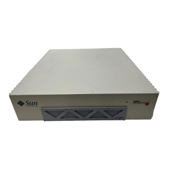
Page 24: Figure 1-1 Ultra 1 Creator Series Desktop System
Ultra Enterprise 1 Server FIGURE 1-2 The following sections provide a brief description of the Ultra 1 Creator series desktop workstation I/O devices. Also included is a detailed overview of the Ultra 1 Creator series and the Ultra Enterprise 1 system unit features. -
Page 25: I/O Devices (Ultra 1 Creator Series Desktop)
I/O Devices (Ultra 1 Creator Series Desktop) The Ultra 1 Creator series desktop workstation uses the following I/O devices: Keyboard Optical mouse Microphone Color camera One of several types of monitors The following table lists the supported I/O devices and provides a brief description of each device. -
Page 26: Supported I/O Devices (Ultra 1 Creator Series Desktop)
128-Mbyte DSIMMs Fast frame buffer (FFB) graphics (67-MHz graphics clock) with 24-bit color and 8- bit overlay: single buffer FFB, double buffer FFB (Ultra 1 Creator series desktop only). Double buffer FFB with 66-MHz graphics clock (Ultra 1 Creator 3D series desktop... -
Page 27: System Unit Components
Sun sales representative or service provider to confirm a part number prior to ordering a replacement part. System Unit/Server Components TABLE 1-2 Component Part Number Description 501-2486 Ultra 1 Creator Series system board (167-MHz) 501-4134 Ultra 1 Creator Series system board (200-MHz) TOD/NVRAM 525-1430 TOD/NVRAM... - Page 28 370-1579 Speaker Cable assembly 530-1871 TPE cable type 5 Cable assembly 530-2153 SCSI cable/backplane assy Cable assembly 530-2175 Cable, speaker/LED Cable assembly 530-2176 Cable, peripheral power Cable assembly 530-2187 Cable, diskette Ultra 1 Creator Series Service Manual • August 1996...
-
Page 29: Figure 1-3 System Unit Rear View
Serial port B Power outlet (RS-423/RS-232) SBus slot 0 (Female socket) Serial port A UPA slot Power on/standby (RS-423/RS-232) SBus slot 1 Parallel port connector Power inlet MII connector SCSI connector (Male plug) Audio Keyboard/mouse TPE connector connector (4) connector System Unit Rear View FIGURE 1-3 Chapter 1... - Page 30 Disk fan System board Disk drive Power supply Speaker CD-ROM drive (may be exchanged with either 4-mm tape drive or 8-mm tape drive) Diskette drive System Unit with Cover Removed FIGURE 1-4 Ultra 1 Creator Series Service Manual • August 1996...
-
Page 31: Sunvts Overview
C H A P T E R SunVTS Overview ™ This chapter contains an overview of the Sun validation and test suite (SunVTS diagnostic tool/application. The following is the list of the SunVTS diagnostic topics presented in this chapter. “SunVTS Kernel” on page 2 “SunVTS User Interface”... -
Page 32: Sunvts Kernel
2.1.2 SunVTS User Interface The SunVTS user interface (vtsui) diagnostic tool operates in the OpenWindows background. Upon activation, vtsui provides vtsk control, various user options, tests, and read-log files. Ultra 1 Creator Series Service Manual • August 1996... -
Page 33: Sunvts Teletype
2.1.3 SunVTS Teletype The SunVTS teletype (vtstty) diagnostic tool controls the vtsk from either a command shell or a terminal attached to a serial port. Most options available in vtstty have equivalent options in vtsui. Chapter 2 SunVTS Overview... - Page 34 Ultra 1 Creator Series Service Manual • August 1996...
-
Page 35: Power-On Self-Test
C H A P T E R Power-On Self-Test his chapter contains procedures to initiate the Power-on self-test (POST) diagnostics. Procedures are also included to support pre-POST preparation, POST data interpretation, and bypassing POST diagnostics. The following is a list of the POST diagnostic topics presented in this chapter. -
Page 36: Pre-Post Preparation
Sun workstation monitor or TTY-type terminal. The tip connection is used in a SunOS window and provides features to help with the OBP. To set up a tip connection: Ultra 1 Creator Series Service Manual • August 1996... - Page 37 1. Connect serial port A of the system being tested to another Sun Workstation serial port B using a serial null modem cable (connect cable pins 2-3, 3-2, 7-20, and 20-7). 2. At the other Sun workstation, check the /etc/remote file: hardwire:\ :dv=/dev/term/b:br#9600:el=^C^S^Q^U^D:ie=%$:oe=^D: Note –...
-
Page 38: Verifying The Baud Rate
2. At the Sun type-5 keyboard, power cycle the system by simultaneously pressing the shift key and the power-on key ( ). After a few seconds, press the FIGURE 3-1 power-on key. 3. Verify the following: Ultra 1 Creator Series Service Manual • August 1996... -
Page 39: Max And Min Levels Of Post
a. The display prompt disappears. b. The monitor power-on indicator flashes on and off. c. The keyboard Caps Lock key indicator flashes on and off. 4. When the POST is complete, set the diag-switch? variable to false (default setting). Scroll Lock Power-on key key indicator Stop... -
Page 40: Diag-Level Nvram Variable Set To Max
0> Ecache size XXXX Kb 0> Ecache size XXXX Kb 0>Ecache Tag Test 0>Ecache RAM Test 0>Ecache Address Line Test 0>Initialize and Verify Ecache 0>SC Initialization 0> SC_MP id=XXXX, UPA Number=X, Impl=X, Ver=X 0>BMX Test Ultra 1 Creator Series Service Manual • August 1996... - Page 41 Diag-level NVRAM Variable Set to Max (Continued) CODE EXAMPLE 3-1 0> Checking BMX's 0>Probing Memory 0> Found Memory Group (Variable based upon memory configuration) 0> Found (Variable based upon memory configuration) of usable Main Memory 0>SIMM Group Base Addr Size Group Status 0>...
- Page 42 Dcache Init 0> Dcache Enable Test 0> Dcache Functionality Test 0>FEPS Test 0> Parallel Port Registers Test 0> Parallel Port ID is: XxX 0> Parallel Port DVMA burst mode read/write Test Ultra 1 Creator Series Service Manual • August 1996...
-
Page 43: Diag-Level Nvram Variable Set To Min
Diag-level NVRAM Variable Set to Max (Continued) CODE EXAMPLE 3-1 0> FAS366 Registers Test 0> ESP FAS366 DVMA burst mode read/write Test 0> FEPS Internal Loopbacks Test 0> Ethernet Transceiver Internal Loopbacks Test 0>CPU Functional Test 0> Mapping Selftest Enabling MMUs 0>... -
Page 44: Post Progress And Error Reporting
If an error occurs during the POST execution, the keyboard Caps Lock key indicator stops flashing and an error code is displayed using the Caps Lock, Compose, Scroll Lock, and Num Lock key indicators. The error code indicates a particular system hardware failure. 3-10 Ultra 1 Creator Series Service Manual • August 1996... -
Page 45: Typical Error Code Failure Message
Note – An error code may only be visible for a few seconds. Observe the Caps Lock, Compose, Scroll Lock, and Num Lock key indicators closely while POST is active. In most cases, POST also attempts to send a failure message to the POST monitoring system. -
Page 46: Additional Keyboard Control Commands
LEDs to indicate the defective part. If POST completes with ‰ no errors, all LEDs will be turned off before returning to the OpenBoot PROM (OBP). 3-12 Ultra 1 Creator Series Service Manual • August 1996... -
Page 47: System Board Test
defines the keyboard LED patterns. on page 3-5 shows the TABLE 3-2 FIGURE 3-1 location of the LED keys on the Sun type 5-c keyboard. Keyboard LED Patterns TABLE 3-2 Caps Lock Compose Scroll Lock Num Lock Bit Value Meaning of LED Pattern Blink x000(2) POST in progress... - Page 48 6. To receive additional POST failure information, establish a tip connection. See Section 3.2.1 “Setting Up a Tip Connection” on page 3-2. 3-14 Ultra 1 Creator Series Service Manual • August 1996...
-
Page 49: Troubleshooting Procedures
C H A P T E R Troubleshooting Procedures This chapter describes how to troubleshoot possible problems and includes the corrective actions you can take. “Power-On Failure” on page 1 “Video Output Failure” on page 2 “Disk or CD-ROM Drive Failure” on page 2 “Power Supply Test”... -
Page 50: Video Output Failure
Replace the monitor or the graphics card. Disk or CD-ROM Drive Failure The following provides examples of disk drive and CD-ROM drive failure symptoms and suggested actions. SYMPTOM Ultra 1 Creator Series Service Manual • August 1996... -
Page 51: Table 4-1 Internal Drives Identification
A disk drive read, write, or parity error is reported by the operating system or customer application. A CD-ROM drive read error or parity error is reported by the operating system or customer applications. ACTION Replace the drive indicated by the failure message. The operating system identifies the internal drives as identified in TABLE 4-1 Internal Drives Identification... -
Page 52: Power Supply Test
Verify +12 VDC, -12 VDC, +5 VDC, +3.3 VDC and +3.0 VDC. c. If any power pin signal is not present with the power supply active and properly connected to the system board, replace the power supply. Ultra 1 Creator Series Service Manual • August 1996... -
Page 53: Figure 4-1 Power Supply Connector J2601
Power Supply Connector J2601 FIGURE 4-1 Connector 2601 Pin Description TABLE 4-2 Description Description +12V Thermal sensor -12V Power on Power off Not used Undefined Not used Undefined +3V sense +3V set Thermal sensor +3V ovp Power on reset Chapter 4 Troubleshooting Procedures... -
Page 54: Figure 4-2 Power Supply Connector J2603
Power Supply Connector J2603 FIGURE 4-2 Connector 2603 Pin Description TABLE 4-3 Description Description +3.3V +3.3V +3.3V +3.0V +3.0V +3.0V Ultra 1 Creator Series Service Manual • August 1996... -
Page 55: Dsimm Failure
DSIMM Failure At times the operating system, diagnostic program, or POST may not display a DSIMM location (U number) as part of a memory error message. In this situation, the only available information is a physical memory address and failing byte (or bit). to locate the defective DSIMM. -
Page 56: Openboot Prom On-Board Diagnostics
Watching the 'seconds' register of It should be 'ticking' once the real time clock chip. a second. Type any key to stop. 41 is an example. Counter increments from 0 to 59 Ultra 1 Creator Series Service Manual • August 1996... -
Page 57: Watch-Net, Watch-Tpe, And Watch-Net-All
4.6.2 watch-net, watch-tpe, and watch-net- watch-net, watch-tpe, and watch-net-all monitor Ethernet packets on the Ethernet cable(s) connected to the system. Good packets received by the system are indicated by a period (.). Errors such as the framing error and the cyclic redundancy check (CRC) error are indicated with an X and an associated error description. -
Page 58: Probe-Scsi And Probe-Scsi-All
SCSI devices connected to the Ultra 1 Creator series on-board SCSI interface. If the SCSI device is connected and active, the target address, unit number, device type, and manufacturer name is displayed. - Page 59 identifies the probe-scsi output message and CODE EXAMPLE 4-4 CODE EXAMPLE 4-5 identifies the probe-scsi-all output message. probe-scsi Output Message CODE EXAMPLE 4-4 ok probe-scsi This command may hang the system if a Stop-A or halt command has been executed. Please type reset- all to reset the system before executing this command.
-
Page 60: Test
If a device has no self-test program, the message: No selftest method for <device name> is displayed. To enable the self-test program for a device, enter the test command followed by the device alias or 4-12 Ultra 1 Creator Series Service Manual • August 1996..., , -All -
Page 61: Ffb Card
device path name. identifies the test output message. CODE EXAMPLE 4-6 TABLE 4-5 lists test <alias name> selections, a description of the selection, and preparation. Note – The floppy drive is selected as the test <alias name> example. test Output Message CODE EXAMPLE 4-6 ok test floppy Testing floppy disk system. - Page 62 A series of patterns are displayed. b. FFB Frame Buffer functional test passed appears. 4. When the FFB on-board diagnostics are completed, enter setenv diag-switch? false. The diag-switch? = false is displayed. 4-14 Ultra 1 Creator Series Service Manual • August 1996...
-
Page 63: Safety And Tool Requirements
C H A P T E R Safety and Tool Requirements This chapter provides a description of safety requirements, symbols, safety precautions, and tools required. “Safety Requirements” on page 1 “Symbols” on page 1 “Safety Precautions” on page 2 “Tools Required” on page 3 Safety Requirements For protection, observe the following safety precautions when setting up the equipment:... -
Page 64: Safety Precautions
The following safety precautions mean: 5.3.1 Modification to Equipment Caution – Do not make mechanical or electrical modifications to the equipment. Sun Microsystems is not responsible for regulatory compliance of a modified Sun product. 5.3.2 Placement of a Sun Product Caution –... -
Page 65: Power Cord Connection
Power Cord Connection Caution – Not all power cords have the same current ratings. Household extension cords do not have overload protection. Do not use household extension cords with the Sun product.The power switch of this product functions as a standby type device only. - Page 66 Inner side (metal part) of the system unit cover Sun ESD mat, part no. 250-1088 (may be purchased through your Sun sales representative) Disposable ESD mat; shipped with replacement parts or optional system features Ultra 1 Creator Series Service Manual • August 1996...
-
Page 67: Power On And Off
C H A P T E R Power On and Off This chapter explains how to work safely when servicing the Ultra 1 Creator series. “Powering On the System” on page 1 “Powering Off the System” on page 2 Powering On the System To power-on the system, proceed as follows. -
Page 68: Powering Off The System
Caution – Disconnect the AC power cord from the AC receptacle prior to handling the power supply. When servicing system components other than the power supply, the AC power cord should remain connected to the AC receptacle. Ultra 1 Creator Series Service Manual • August 1996... - Page 69 6. When the power on/standby switch is in stand-by (0) and the AC power cord remains connected to a power receptacle, AC voltage is present in the power supply primary. 7. Turn off the power to the monitor. 8. Disconnect cables to any peripheral equipment. Chapter 6 Power On and Off...
- Page 70 Ultra 1 Creator Series Service Manual • August 1996...
-
Page 71: Internal Access
C H A P T E R Internal Access This section provides step-by-step procedures to remove the Ultra 1 Creator series cover, attach the wrist strap, and replace the cover. “Removing the Cover” on page 1 “Attaching the Wrist Strap” on page 2 “Replacing the Cover”... -
Page 72: Attaching The Wrist Strap
ESD-sensitive components in antistatic bags before placing it on any surface. 1. Unwrap the first two folds of the wrist strap; wrap the adhesive side firmly against the wrist ( FIGURE 7-3 Ultra 1 Creator Series Service Manual • August 1996... -
Page 73: Replacing The Cover
2. Peel the liner from the copper foil at the opposite end of the wrist strap. Attach the copper end of the wrist strap to the power supply top. Wrist strap Copper foil end Power supply Attaching the Wrist Strap FIGURE 7-3 Replacing the Cover To replace the cover:... -
Page 74: Figure 7-4 Replacing The Cover
5. Power-on the system. Channel (2 places) Cover Flange Captive screw (2) Flange Replacing the Cover FIGURE 7-4 Ultra 1 Creator Series Service Manual • August 1996... -
Page 75: Major Subassemblies
C H A P T E R Major Subassemblies This chapter contains procedures to remove and replace the major subassemblies of the system and server units. The following is a list of the major subassemblies: “Power Supply” on page 1 “Disk Drive Fan”... - Page 76 7. Push the power supply toward the front side of the chassis to disengage the mounting hooks. 8. Tilt the power supply slightly toward the system board; lift the power supply from the chassis. Ultra 1 Creator Series Service Manual • August 1996...
-
Page 77: Replacing The Power Supply
Clip DC Harness Power supply J2603 J2601 Captive screw Removing the Power Supply FIGURE 8-1 8.1.2 Replacing the Power Supply Caution – Use proper ESD grounding techniques when handling components. Wear an antistatic wrist strap and use an ESD-protected mat. Store ESD-sensitive components in antistatic bags before placing it on any surface. -
Page 78: Figure 8-2 Replacing The Power Supply
Connect the power supply connector to the system board at J2601. 5. Detach the wrist strap. 6. Replace the system unit cover. See Section 7.3 “Replacing the Cover” on page 7-3. Ultra 1 Creator Series Service Manual • August 1996... -
Page 79: Disk Drive Fan
7. Power-on the system. See Section 6.1 “Powering On the System” on page 6-1. Clip Power supply J2603 J2601 Captive screw Securing and Connecting the Power Supply FIGURE 8-3 Disk Drive Fan To remove and replace the disk drive fan assembly, proceed as follows. Chapter 8 Major Subassemblies... -
Page 80: Removing The Disk Drive Fan Assembly
4. Disconnect the fan power cable from the fan ( FIGURE 8-4 Fan power cable Fan Power Cable Connection FIGURE 8-4 5. Prepare to remove the fan assembly as follows FIGURE 8-5 Ultra 1 Creator Series Service Manual • August 1996... -
Page 81: Replacing The Disk Drive Fan
a. Press the middle tab on the fan/speaker bracket toward the center of the chassis. b. Grasp the fan and pull it from the fan/speaker bracket. Disk drive fan Fan/speaker bracket Chassis Middle tab Disk Drive Fan FIGURE 8-5 8.2.2 Replacing the Disk Drive Fan Caution –... -
Page 82: Figure 8-6 Replacing The Disk Drive Fan
4. Detach the wrist strap. 5. Replace the system unit cover. See Section 7.3 “Replacing the Cover” on page 7-3. 6. Power-on the system. See Section 6.1 “Powering On the System” on page 6-1. Ultra 1 Creator Series Service Manual • August 1996... -
Page 83: Speaker
Speaker To remove and replace the speaker, proceed as follows. 8.3.1 Removing the Speaker 1. Power-off the system. See Section 6.2 “Powering Off the System” on page 6-2. 2. Remove the system unit cover. See Section 7.1 “Removing the Cover” on page 7-1. Caution –... -
Page 84: Figure 8-7 Fan And Speaker Cable Connection
Fan power cable Speaker Speaker connector (2) Fan and Speaker Cable Connection FIGURE 8-7 8-10 Ultra 1 Creator Series Service Manual • August 1996... -
Page 85: Figure 8-8 Removing The Fan/Speaker Bracket
Fan/speaker bracket Chassis Tab (3) Removing the Fan/Speaker Bracket FIGURE 8-8 5. Release the bottom portion of the speaker from the bracket and remove the speaker ( FIGURE 8-9 Chapter 8 Major Subassemblies 8-11... -
Page 86: Replacing The Speaker
FIGURE 8-10 a. Position the speaker in the fan/speaker bracket. b. Insert the fan/speaker bracket into the chassis. c. Verify the tabs are locked into the chassis to ensure proper replacement. 8-12 Ultra 1 Creator Series Service Manual • August 1996... -
Page 87: Figure 8-10 Replacing The Fan/Speaker Bracket
Fan power cable Speaker cable Fan/speaker bracket Chassis Tab (3) Replacing the Fan/Speaker Bracket FIGURE 8-10 Note – Ensure the speaker connectors are on the top. 2. Connect the speaker as follows ( FIGURE 8-7 a. Use needle-nose pliers to connect the speaker cable to the speaker. Note –... -
Page 88: Diskette Cable
Remove the DC harness from the clip located on the drive bracket. c. Push the drive bracket toward the disk drive bay; gently flip the drive bracket over. d. Place the drive bracket on top of the disk drive bay. 8-14 Ultra 1 Creator Series Service Manual • August 1996... -
Page 89: Figure 8-11 Removing The Drive Bracket
5. Disconnect the diskette cable from the diskette drive. 6. Disconnect the diskette cable from the SCSI backplane. 7. Remove the diskette cable. Clip Mounting screw (2) Removing the Drive Bracket FIGURE 8-11 Chapter 8 Major Subassemblies 8-15... -
Page 90: Replacing The Diskette Cable
1. Connect the diskette cable to the socket (marked FLOPPY) on the SCSI backplane. 2. Connect the diskette cable to the diskette drive ( FIGURE 8-12 8-16 Ultra 1 Creator Series Service Manual • August 1996... - Page 91 Note – If a CD-ROM drive or a tape drive is installed in the system, perform Step 3. 3. Replace the drive bracket as follows ( FIGURE 8-12 FIGURE 8-13 a. Position the drive bracket in the chassis. b. Slide it away toward the openings in the side of the chassis. Note –...
-
Page 92: Scsi Cable/Backplane Assembly
Drive bracket Chassis DC harness Clip Screw (2) Replacing the Drive Bracket FIGURE 8-13 SCSI Cable/Backplane Assembly To remove and replace the SCSI cable/backplane assembly, proceed as follows. 8-18 Ultra 1 Creator Series Service Manual • August 1996... -
Page 93: Removing The Scsi Cable/Backplane Assembly
8.5.1 Removing the SCSI Cable/Backplane Assembly 1. Power-off the system. Section 6.2 “Powering Off the System” on page 6-2. 2. Remove the system unit cover. See Section 7.1 “Removing the Cover” on page 7-1. Caution – Use proper ESD grounding techniques when handling components. Wear an antistatic wrist strap and use an ESD-protected mat. -
Page 94: Figure 8-14 Scsi/Backplane Assembly Cable Connection
SCSI cable Backplane assembly Screw (2) Diskette cable SCSI/Backplane Assembly Cable Connection FIGURE 8-14 8-20 Ultra 1 Creator Series Service Manual • August 1996... -
Page 95: Replacing The Scsi Cable/Backplane Assembly
J2602 Cable Clip (3) SCSI cable Backplane assembly Removing the Backplane Assembly FIGURE 8-15 7. Remove the two screws securing the backplane assembly to the bracket. 8. Disconnect the SCSI cable from J2602 on the system board. Note – J2602 is located between the disk drive bay and the system board. 9. -
Page 96: Figure 8-16 Replacing The Scsi Backplane
5. Connect the following ( FIGURE 8-14 a. The peripheral power cable (P4) to the backplane assembly connector marked PWR. b. The diskette cable (if present) to the backplane assembly connector marked FLOPPY. 8-22 Ultra 1 Creator Series Service Manual • August 1996... -
Page 97: Peripheral Power Cable
Caution – Each drive slot has a unique SCSI target address (lower drive slot is target address 0, upper drive slot is target address 1). Make note of the drive slot for each disk drive. Installing a disk drive into the incorrect drive slot could cause file system or system boot problems. -
Page 98: Figure 8-17 Removing The Drive Bracket
Gently flip the drive bracket over and set on top of the disk drive bay. c. Disconnect the peripheral power cable from the peripherals and the fan TABLE 8-1 6. Remove the peripheral power cable from the cable clips on the backplane assembly. 8-24 Ultra 1 Creator Series Service Manual • August 1996... -
Page 99: Figure 8-18 Removing The Peripheral Power Cable Connection
7. Remove the peripheral power cable. Diskette drive SCSI cable Diskette cable Removing the Peripheral Power Cable Connection FIGURE 8-18 Peripheral Power Cable Connections TABLE 8-1 Connector Peripheral Diskette drive Chapter 8 Major Subassemblies 8-25... -
Page 100: Replacing The Peripheral Power Cable
ESD-protected mat. Store ESD-sensitive components in antistatic bags before placing it on any surface. 1. Connect the peripheral power cable to each peripheral ( TABLE 8-1 FIGURE 8-20 8-26 Ultra 1 Creator Series Service Manual • August 1996... -
Page 101: Figure 8-20 Replacing The Peripheral Power Cable Connection
Disk drive SCSI cable Diskette cable Replacing the Peripheral Power Cable Connection FIGURE 8-20 2. Route the peripheral power cable through the backplane assembly cable clips FIGURE 8-19 3. Position and secure the drive bracket as follows ( FIGURE 8-21 a. -
Page 102: Figure 8-21 Replacing The Drive Bracket
See Section 7.3 “Replacing the Cover” on page 7-3. 6. Power-on the system. See Section 6.1 “Powering On the System” on page 6-1. Drive bracket Chassis DC harness Clip Screw (2) Replacing the Drive Bracket FIGURE 8-21 8-28 Ultra 1 Creator Series Service Manual • August 1996... -
Page 103: Speaker/Led Cable
Speaker/LED Cable To remove and replace the speaker/LED cable, proceed as follows. 8.7.1 Removing the Speaker/LED Cable 1. Power-off the system. See Section 6.2 “Powering Off the System” on page 6-2. 2. Remove the system unit cover. See Section 7.1 “Removing the Cover” on page 7-1. Caution –... -
Page 104: Figure 8-22 Removing The Drive Bracket
FIGURE 8-23 a. Push the CD-ROM/tape drive bracket toward the disk drive bay and gently flip it over. b. Place the CD-ROM/tape drive bracket on top of the disk drive bay. 8-30 Ultra 1 Creator Series Service Manual • August 1996... -
Page 105: Figure 8-23 Placing The Bracket On Top Of The Disk Drive
Drive bracket CD-ROM drive/tape drive Disk drive bay Placing the Bracket on Top of the Disk Drive FIGURE 8-23 6. Slide the LED from the cavity and remove the speaker/LED cable from the two cable clips ( FIGURE 8-24 Chapter 8 Major Subassemblies 8-31... - Page 106 See Section 10.3.1 “Removing an SBus Card” on page 10-14. 9. Disconnect the speaker/LED cable from the system board at J2001 ( FIGURE 8-26 10. Pull the speaker/LED cable from the chassis, removing it from the backplane assembly clips. 8-32 Ultra 1 Creator Series Service Manual • August 1996...
-
Page 107: Figure 8-25 Speaker/Led Cable Connection
Speaker Speaker connector (2) Speaker/LED Cable Connection FIGURE 8-25 Speaker/LED cable System board J2001 Speaker Connector on the System Board FIGURE 8-26 Chapter 8 Major Subassemblies 8-33... -
Page 108: Replacing The Speaker/Led Cable
6. Connect the DC harness to the peripheral power cable at P1. 7. Route the DC power harness through the drive bracket clip. 8. Replace the two screws securing the drive bracket to the chassis. 8-34 Ultra 1 Creator Series Service Manual • August 1996... -
Page 109: Figure 8-27 Replacing The Drive Bracket
Drive bracket Chassis Hole (3) DC Harness Clip Screw (2) Replacing the Drive Bracket FIGURE 8-27 Chapter 8 Major Subassemblies 8-35... - Page 110 8-36 Ultra 1 Creator Series Service Manual • August 1996...
-
Page 111: Storage Devices
C H A P T E R Storage Devices This chapter contains procedures to remove and replace the storage devices of the system and server units. The following is the list of the storage devices and support hardware: “Disk Drive” on page 1 “Media Bay Chassis Bracket”... -
Page 112: Figure 9-1 Emi Door
EMI Door FIGURE 9-1 6. Fully extend the disk drive handle to disconnect the disk drive from the system FIGURE 9-2 Disk drive Drive handle Removing the Disk Drive FIGURE 9-2 Ultra 1 Creator Series Service Manual • August 1996... -
Page 113: Replacing A Disk Drive
7. Hold the drive handle and pull it out to remove the disk drive from the chassis. Note – The disk drive rear connector is disconnected when the disk drive is ejected. 8. Place the disk drive on an antistatic surface. 9.1.2 Replacing a Disk Drive Caution –... -
Page 114: Figure 9-3 Replacing The Disk Drive
4. Detach the wrist strap. 5. Replace the system unit cover. See Section 7.3 “Replacing the Cover” on page 7-3. 6. Power-on the system. See Section 6.1 “Powering On the System” on page 6-1. Ultra 1 Creator Series Service Manual • August 1996... -
Page 115: Media Bay Chassis Bracket
Chassis EMI door Replacing the EMI Door FIGURE 9-4 Media Bay Chassis Bracket It is necessary to remove and replace the media bay chassis bracket (chassis bracket) in order to remove and replace either the CD-ROM drive (or 4-mm/8-mm tape drive) or the diskette drive. -
Page 116: Figure 9-5 Chassis Bracket
Disconnect the peripheral power cable from the CD-ROM drive or tape drive (P3), and from the diskette drive (P2) if any. d. Disconnect the diskette cable from the diskette drive (if any). 4. Place the chassis bracket on an antistatic surface. Ultra 1 Creator Series Service Manual • August 1996... -
Page 117: Replacing The Chassis Bracket
Chassis bracket Disk drive bay SCSI cable Diskette cable Placing the Chassis Bracket on Top of the Disk Drive FIGURE 9-6 9.2.2 Replacing the Chassis Bracket Caution – Use proper ESD grounding techniques when handling components. Wear an antistatic wrist strap and use an ESD-protected mat. Store ESD-sensitive components in antistatic bags before placing it on any surface. -
Page 118: Figure 9-7 Connecting Cables To The Cd-Rom Drive, 4-Mm/8-Mm Tape Drive, And Diskette Drive
The SCSI cable to the CD-ROM drive or tape drive. Disk drive bay SCSI cable Diskette cable Connecting Cables to the CD-ROM Drive, 4-mm/8-mm Tape Drive, and FIGURE 9-7 Diskette Drive Ultra 1 Creator Series Service Manual • August 1996... -
Page 119: Figure 9-8 Positioning The Chassis Bracket
2. Position the chassis bracket in the chassis and slide the chassis bracket toward the opening in the chassis side ( FIGURE 9-8 3. Connect the DC harness to the peripheral power cable at P1. Chassis bracket Chassis Bottom hole (3) Clip Screw (2) Positioning the Chassis Bracket... -
Page 120: Cd-Rom Drive Or 4-Mm/8-Mm Tape Drive
Remove the four screws securing the CD-ROM drive or 4-mm/8-mm tape drive to the chassis bracket. 6. Remove the CD-ROM drive or 4-mm/8-mm tape drive. 7. Place the CD-ROM drive or 4-mm/8-mm tape drive aside on an antistatic surface. 9-10 Ultra 1 Creator Series Service Manual • August 1996... -
Page 121: Replacing A Cd-Rom Drive Or 4-Mm/8-Mm Tape Drive
Screw (4) Chassis bracket Diskette drive CD-ROM drive or 4-mm/8-mm tape drive Positioning the CD-ROM Drive or 4-mm/8-mm Tape Drive FIGURE 9-9 9.3.2 Replacing a CD-ROM Drive or 4-mm/8-mm Tape Drive Caution – Use proper ESD grounding techniques when handling components. Wear an antistatic wrist strap and use an ESD-protected mat. -
Page 122: Diskette Drive
3. Attach the wrist strap. See Section 7.2 “Attaching the Wrist Strap” on page 7-2. 4. Remove the chassis bracket. See Section 9.2.1 “Removing the Chassis Bracket” on page 9-5. 9-12 Ultra 1 Creator Series Service Manual • August 1996... -
Page 123: Figure 9-10 Positioning The Diskette Drive
5. Remove the CD-ROM drive or 4-mm/8-mm tape drive. See Section 9.3.1 “Removing a CD-ROM Drive or 4-mm/8-mm Tape Drive” on page 9-10. 6. Remove the four screws securing the diskette drive to the chassis bracket FIGURE 9-10 7. Remove the diskette drive. 8. -
Page 124: Replacing A Diskette Drive
See Section 9.3.2 “Replacing a CD-ROM Drive or 4-mm/8-mm Tape Drive” on page 9-11. 4. Replace the chassis bracket into the chassis. See Section 9.2.2 “Replacing the Chassis Bracket” on page 9-7. 5. Detach the wrist strap. 9-14 Ultra 1 Creator Series Service Manual • August 1996... - Page 125 6. Replace the system unit cover. See Section 7.3 “Replacing the Cover” on page 7-3. 7. Power-on the system. See Section 6.1 “Powering On the System” on page 6-1. Chapter 9 Storage Devices 9-15...
- Page 126 9-16 Ultra 1 Creator Series Service Manual • August 1996...
-
Page 127: System Board And Component Replacement
C H A P T E R System Board and Component Replacement This chapter contains removal and replacement procedures for the system board and components of the system board. The following is a list of topics presented. “System Board” on page 1 “NVRAM/TOD”... -
Page 128: Removing A System Board
Remove the FFB card (workstation only). See Section 10.4.1 “Removing an FFB Card” on page 10-19. 6. Disconnect the following: a. SCSI cable. See Section 8.5.1 “Removing the SCSI Cable/Backplane Assembly” on page 8-19. 10-2 Ultra 1 Creator Series Service Manual • August 1996... -
Page 129: Figure 10-1 Dc Power Disconnection
b. Speaker/LED cable. See Section 8.7.1 “Removing the Speaker/LED Cable” on page 8-29. c. DC power cables at J2601 and J2603 ( FIGURE 10-1 J2603 J2601 System board DC Power Disconnection FIGURE 10-1 7. Loosen the two captive screws that secure the system board back panel to the chassis ( FIGURE 10-2 8. -
Page 130: Replacing A System Board
Caution – Use proper ESD grounding techniques when handling components. Wear an antistatic wrist strap and use an ESD-protected mat. Store ESD-sensitive components in antistatic bags before placing it on any surface. 10-4 Ultra 1 Creator Series Service Manual • August 1996... -
Page 131: Figure 10-4 Removing Sbus Filler Panels From The Back Panel
1. Remove the SBus filler panel(s) from the replacement system board as follows: a. Squeeze the filler panel bottom locking tabs to unhook them from the back panel ( FIGURE 10-4 Back panel SBus filler panel Locking tab (2) Removing SBus Filler Panels from the Back Panel FIGURE 10-4 b. -
Page 132: Figure 10-5 Card Guide Exploded View
Vertical tab Card guide Registration pin Card Guide Exploded view FIGURE 10-5 10-6 Ultra 1 Creator Series Service Manual • August 1996... -
Page 133: Figure 10-6 Installing The Card Guide
Front edge slot Vertical tab Card guide Front edge slot Registration pin Installing the Card Guide FIGURE 10-6 3. Slide the system board into the chassis rear. Verify that both sides of the system board fit into the chassis plastic board guide slots ( FIGURE 10-7 4. -
Page 134: Figure 10-7 Sliding The System Board Into The Chassis
All SBus card(s). See Section 10.3.2 “Replacing an SBus Card” on page 10-16. All DSIMMs. Section 10.5.2 “Replacing a DSIMM” on page 10-26. The FFB card (workstation only). See Section 10.4.2 “Replacing an FFB Card” on page 10-21. 10-8 Ultra 1 Creator Series Service Manual • August 1996... -
Page 135: Figure 10-8 Dc Power Connection
J2603 J2601 System board DC Power Connection FIGURE 10-8 6. Use a pair of long-nose pliers to set the system board serial port jumpers J2104 and J2105. TABLE 10-1 FIGURE 10-9 Serial Port Jumper Settings TABLE 10-1 Default Shunt Jumper Pins 1 + 2 Select Pins 2 + 3 Select on Pins... - Page 136 Note – The Solaris operating environment Power Management software uses the #power-cycles NVRAM variable to control the frequency of automatic system shutdown if automatic shutdown is enabled. 10-10 Ultra 1 Creator Series Service Manual • August 1996...
- Page 137 Back panel SCSI Parallel port Audio ports J2003-J2204 System board Power supply UPA slot SBus slot 0 CPU chip set SBus slot 1 DSIMM slots: U601— U604 UPPER — CD-ROM drive or 4-mm/8-mm tape drive UPPER — Disk drive LOWER — Diskette drive LOWER —...
-
Page 138: Nvram/Tod
5. Grasp the NVRAM/TOD carrier at each end. Lift the NVRAM/TOD carrier straight up. Note – Gently wiggle the NVRAM/TOD as necessary. 6. Place the NVRAM/TOD and carrier on an antistatic surface. 10-12 Ultra 1 Creator Series Service Manual • August 1996... -
Page 139: Replacing A Nvram/Tod
System board NVRAM/TOD NVRAM/TOD FIGURE 10-11 10.2.2 Replacing a NVRAM/TOD Caution – Use proper ESD grounding techniques when handling components. Wear an antistatic wrist strap and use an ESD-protected mat. Store ESD-sensitive components in antistatic bags before placing it on any surface. 1. -
Page 140: Sbus Card
See Section 6.2 “Powering Off the System” on page 6-2. 2. Disconnect all cables from the SBus slots ( FIGURE 10-12 SBus slot 1 UPA slot SBus slot 0 System board SBus Slot Locations. FIGURE 10-12 10-14 Ultra 1 Creator Series Service Manual • August 1996... -
Page 141: Figure 10-13 Removing An Sbus Card From Slot 0 Or
3. Remove the unit cover. See Section 7.1 “Removing the Cover” on page 7-1. Caution – Use proper ESD grounding techniques when handling components. Wear an antistatic wrist strap and use an ESD-protected mat. Store ESD-sensitive components in antistatic bags before placing it on any surface. 4. -
Page 142: Replacing An Sbus Card
Remove the two screws that secure the backplate adapter to the backplate. b. Remove the backplate adapter. c. Identify the SBus slot and open the SBus card retainers. d. Discard the screws and backplate adapter. 10-16 Ultra 1 Creator Series Service Manual • August 1996... -
Page 143: Removing The Sbus Card Adapter Bracket
10.3.3 Removing the SBus Card Adapter Bracket 1. Remove the SBus card extractor (if any) as follows ( FIGURE 10-14 a. Slightly bend one extractor leg towards the outside until the extractor leg hook clears the SBus card hole. b. Remove the other side of the extractor. SBus card extractor SBus card Removing the SBus Card Extractor... -
Page 144: Figure 10-15 Replacing The Sbus Card
6. Connect all cables to the SBus slots. 7. Power-on the system. See Section 6.1 “Powering On the System” on page 6-1. Back panel tabs (2) Card backplate Card retainer (2) Replacing the SBus Card FIGURE 10-15 10-18 Ultra 1 Creator Series Service Manual • August 1996... -
Page 145: Ffb Card (Workstation Only)
10.4 FFB Card (Workstation Only) To remove and replace the FFB card, proceed as follows. Note – Illustrations supporting the FFB card removal and replacement are not representative of a system unit or sever chassis. 10.4.1 Removing an FFB Card 1. - Page 146 6. Hold the FFB card at each corner and gently pull the FFB card up to disconnect it from the UPA socket ( FIGURE 10-17 Back panel Backplate FFB board UPA slot Removing the FFB Card FIGURE 10-17 10-20 Ultra 1 Creator Series Service Manual • August 1996...
-
Page 147: Replacing An Ffb Card
Caution – Avoid applying unequal force to one end or one side of the FFB card or connector pin damage may occur. 7. Slowly lift the FFB card at an upward angle. 8. Lower the FFB card backplate. 9. Disengage the FFB card backplate from the back panel. 10. -
Page 148: Figure 10-19 Seating An Ffb Card Into The Upa Socket
See Section 7.3 “Replacing the Cover” on page 7-3. 9. Connect the video cable to the 13W3 video connector. 10. Power-on the system. See Section 6.1 “Powering On the System” on page 6-1. 10-22 Ultra 1 Creator Series Service Manual • August 1996... -
Page 149: Dsimm
Caution – When removing a DSIMM an identical replacement is required. The replacement DSIMM must be inserted into the same socket as the removed DSIMM. The Ultra 1 Creator series system must have at least two identical DSIMMs installed in paired sockets of any DSIMM bank. -
Page 150: Removing A Dsimm
3. Attach the wrist strap. See Section 7.2 “Attaching the Wrist Strap” on page 7-2. 4. Locate the DSIMM to be removed. 5. Push the lever away from the DSIMM ( FIGURE 10-21 10-24 Ultra 1 Creator Series Service Manual • August 1996... -
Page 151: Figure 10-21 Dsimm Ejection Lever
DSIMM DSIMM Ejection lever DSIMM Ejection Lever FIGURE 10-21 6. Remove the DSIMM from the socket ( FIGURE 10-22 Chapter 10 System Board and Component Replacement 10-25... -
Page 152: Replacing A Dsimm
Caution – Do not remove any DSIMM from the anti-static container until ready to install it on the system board. Handle DSIMMs only by their edges. Do not touch DSIMM components or metal parts. Always wear a grounding strap when handling DSIMMs. 10-26 Ultra 1 Creator Series Service Manual • August 1996... - Page 153 Caution – Each DSIMM bank must contain two DSIMMs of equal density (for example: two 16-Mbyte DSIMMs) to function properly. Do not mix DSIMM density in any bank. Caution – Use proper ESD grounding techniques when handling components. Wear an antistatic wrist strap and use an ESD-protected mat. Store ESD-sensitive components in antistatic bags before placing it on any surface.
-
Page 154: System Board Fan
Removing the System Board Fan 1. Power-off the system. See Section 6.2 “Powering Off the System” on page 6-2. 2. Remove the unit cover. See Section 7.1 “Removing the Cover” on page 7-1. 10-28 Ultra 1 Creator Series Service Manual • August 1996... -
Page 155: Figure 10-24 System Board Fan Plastic Cover
Caution – Use proper ESD grounding techniques when handling components. Wear an antistatic wrist strap and use an ESD-protected mat. Store ESD-sensitive components in antistatic bags before placing it on any surface. 3. Attach the wrist strap. See Section 7.2 “Attaching the Wrist Strap” on page 7-2. 4. -
Page 156: Replacing The Board Fan
3. Position the plastic cover on top of the system board fan. 4. Replace the two screws securing the plastic cover and system board fan to the system board ( FIGURE 10-24 10-30 Ultra 1 Creator Series Service Manual • August 1996... - Page 157 5. Detach the wrist strap. 6. Replace the unit cover. See Section 7.3 “Replacing the Cover” on page 7-3. 7. Connect the video cable to the 13W3 video connector. 8. Power-on the system. See Section 6.1 “Powering On the System” on page 6-1. Chapter 10 System Board and Component Replacement 10-31...
- Page 158 10-32 Ultra 1 Creator Series Service Manual • August 1996...
-
Page 159: Replacement Parts
C H A P T E R Replacement Parts This chapter lists the authorized replaceable parts for the Ultra 1 Creator series system unit and the Ultra Enterprise 1 server. lists replaceable parts by TABLE 11-1 nomenclature and part number. A brief description is also provided. - Page 160 Speaker Cable assembly 530-1871 TPE cable type 5 Cable assembly 530-2153 SCSI cable/backplane assy Cable assembly 530-2175 Cable, speaker/LED Cable assembly 530-2176 Cable, peripheral power Cable assembly 530-2187 Cable, diskette 11-2 Ultra 1 Creator Series Service Manual • August 1996...
-
Page 161: Product Specifications
A P P E N D I X Product Specifications This appendix provides product specifications for the Ultra 1 Creator series system (system unit) and the Ultra Enterprise 1 server (server) and is divided into three parts: Physical specifications Electrical specifications... - Page 162 Current, maximum 3.1 to 1.5A Current frequency range 47 to 63 Hz Output +5V, 18A Output +3.3V, 12 A Output +2.5 to 3.6 V, 12 to 8.3 A Output +12V, 5.1 A Ultra 1 Creator Series Service Manual • August 1996...
- Page 163 -12V, 0.3 A Input Power rating 260 W Volt-Ampere rating 260 VA Power factor >0.98 Environmental Requirements lists environmental requirements for the Ultra 1 Creator Series system. TABLE A-5 Environmental Requirements TABLE A-5 Environmental Operating Non-operating Temperature 41 to 104° F (5 to 40° C) -40 to 140°...
- Page 164 Ultra 1 Creator Series Service Manual • August 1996...
- Page 165 A P P E N D I X Signal Descriptions This appendix provides signal descriptions for the Ultra 1 Creator series desktop workstation and the Ultra Enterprise 1 server back panel connectors. Tables B-1 through B-9 list connector pin assignments and signal descriptions. An illustration of each connector is also provided.
-
Page 166: Figure B-1 Keyboard/Mouse Connector Pin Configuration
The serial ports A and B connector are DB-25 type connectors located on the system board back panel. illustrates the serial port A and serial port B connector FIGURE B-2 configuration. lists the serial A and B port connector pin assignments. TABLE B-2 Ultra 1 Creator Series Service Manual • August 1996... -
Page 167: Figure B-2 Serial Ports A And B Connector Configuration
Serial port A Serial port B Serial Ports A and B Connector Configuration FIGURE B-2 Serial A and B Port Connector Pin Assignments TABLE B-2 Signal Name Description Not connected None Transmit Data Receive Data Ready To Send Clear To Send Data Set Ready Signal Ground Data Carrier Detect... -
Page 168: Tpe (Twisted Pair Ethernet) Connector
TPE (Twisted Pair Ethernet) Connector The TPE connector is a RJ-45 type connector located on the system board back panel. illustrates the TPE connector configuration. lists the TPE FIGURE B-3 TABLE B-3 connector pin assignments. Ultra 1 Creator Series Service Manual • August 1996... -
Page 169: Figure B-3 Tpe Connector Configuration
TPE Connector Configuration FIGURE B-3 TPE Connector Pin Assignments TABLE B-3 Signal Name Description tpe0 Transmit data + tpe1 Transmit data - tpe2 Receive data + Common mode termination Termination Common mode termination Termination tpe3 Receive data - Common mode termination Termination Common mode termination Termination... -
Page 170: Figure B-4 Fast Wide Scsi Connector Configuration
Fast Wide SCSI Connector Configuration FIGURE B-4 Fast Wide SCSI Connector Pin Assignments TABLE B-4 Signal Name Description Ground Ground Ground Ground Ground Ground Ground Ground Ground Ground Ground Ground Ground Ground Ground Ground Ultra 1 Creator Series Service Manual • August 1996... - Page 171 Fast Wide SCSI Connector Pin Assignments (Continued) TABLE B-4 Signal Name Description Termpower Termpower Termpower Termpower Not used Undefined Ground Ground Ground Ground Ground Ground Ground Ground Ground Ground Ground Ground Ground Ground Ground Dat<12>_ Data 12 Dat<13>_ Data 13 Dat<14>_ Data 14 Dat<15>_...
- Page 172 Data 7 Par0 l_ Parity 0 Ground Term_dis_ Term disable Termpower Termpower Termpower Termpower Not used Undefined Ground Atn_ Attention Ground Bsy_ Busy Ack_ Acknowledge Rst_ Reset Msg_ Message Sel_ Select Command Ultra 1 Creator Series Service Manual • August 1996...
-
Page 173: Audio Connectors
Fast Wide SCSI Connector Pin Assignments (Continued) TABLE B-4 Signal Name Description Req_ Request In/Out Dat<8>_ Data 8 Dat<9>_ Data 9 Dat<10>_ Data 10 Dat<11>_ Data 11 Note – _ (underscore) signifies active low Audio Connectors The audio connectors are located on the system board back panel. These connectors use EIA standard 3.5-mm/0.125-inch jacks. -
Page 174: Parallel Port Connector
The parallel port connector is a DB-25 type connector located on the system board back panel. illustrates the parallel port connector configuration. FIGURE B-6 TABLE B-6 lists the parallel port connector pin assignments. B-10 Ultra 1 Creator Series Service Manual • August 1996... -
Page 175: Signal Descriptions
DB-25 Parallel Port Connector Pin Configuration FIGURE B-6 Parallel Port Connector Pin Assignments TABLE B-6 Signal Name Description nStrobe Strobe Data[0] Date bit 0 Data[1] Data bit 1 Data[2] Data bit 2 Data[3] Data bit 3 Data[4] Data bit 4 Data[5] Data bit 5 Data[6... -
Page 176: Mii (Media Independent Interface) Connector
Signal ground MII (Media Independent Interface) Connector The MII connector is located on the system board. illustrates the MII FIGURE B-7 connector configuration. lists the MII connector pin assignment. TABLE B-7 B-12 Ultra 1 Creator Series Service Manual • August 1996... -
Page 177: Figure B-7 Mii Connector Configuration
MII Connector Configuration FIGURE B-7 MII Connector Pin Assignments TABLE B-7 Signal Name Description Power Mdio Management data I/O Management data clock Rxd3 Receive data 3 Rxd2 Receive data 2 Rxd1 Receive data 1 Rxd0 Receive data 0 Rx dv Receive data valid Rx clk Receive clock... - Page 178 TABLE B-7 Signal Name Description Collision detected Carrier sense Power Power Ground Ground Ground Ground Ground Ground Ground Ground Ground Ground Ground Ground Ground Ground Ground Ground Ground Ground Power B-14 Ultra 1 Creator Series Service Manual • August 1996...
-
Page 179: Figure B-8 Upa Connector Pin Configuration
UPA Connector The UPA connector is located on the system board. illustrates the UPA FIGURE B-8 connector configuration. lists the UPA connector pin assignment. TABLE B-8 UPA Connector Pin Configuration FIGURE B-8 UPA Connector Pin Assignments TABLE B-8 Signal Name Description Adrbus1<00>... - Page 180 Address bus bit 28 Ground Ground +12 V +12 volts DC Graphic1 int l Interrupt +12 V +12 volts DC Mod tdi JTAG TDI Adr bus1 val UPA address bus 1 value B-16 Ultra 1 Creator Series Service Manual • August 1996...
- Page 181 UPA Connector Pin Assignments (Continued) TABLE B-8 Signal Name Description Mod1 tms JTAG TMS Tclk2 JTAG clock Trst l JTAG reset Mod1 tdo JTAG tdo S reply3<0> UPA s reply 3<0> S reply3<1> UPA s reply 3<1> S reply3<2> UPA s reply 3<2> Ground Clk pos<4>...
- Page 182 Databus1<20> Data bus bit 20 Databus1<21> Data bus bit 21 Databus1<22> Data bus bit 22 Databus1<23> Data bus bit 23 Databus1<24> Data bus bit 24 Databus1<25> Data bus bit 25 B-18 Ultra 1 Creator Series Service Manual • August 1996...
- Page 183 UPA Connector Pin Assignments (Continued) TABLE B-8 Signal Name Description Databus1<26> Data bus bit 26 Databus1<27> Data bus bit 27 Databus1<28> Data bus bit 28 Databus1<29> Data bus bit 29 Databus1<30> Data bus bit 30 Databus1<31> Data bus bit 31 Databus1<32>...
- Page 184 The graphics card 13W3 video connector is located on the system board back panel. illustrates the graphics card 13W3 video connector configuration. FIGURE B-9 lists the graphics card 13W3 video connector pin assignment. TABLE B-9 B-20 Ultra 1 Creator Series Service Manual • August 1996...
-
Page 185: Figure B-9 Graphics Card 13W3 Video Con
Graphics Card 13W3 Video Con FIGURE B-9 Graphics Card 13W3 Video Connector Pin Assignments TABLE B-9 Signal Name Description Green Blue Serial Read Serial Read Vert Sync Vertical Sync Sense <0> Sense <0> Ground Comp Sync Composite Sync Horiz Sync Horizontal Sync Serial Write Serial Write... - Page 186 B-22 Ultra 1 Creator Series Service Manual • August 1996...
-
Page 187: System Unit/Server Overview
A P P E N D I X Functional Description This section provides a functional description for the Ultra 1 Creator Series system. “System Unit/Server Overview” on page 1 “ASICS” on page 11 “Power Supply” on page 15 “System Board” on page 16 “Jumper Descriptions”... - Page 188 SLAVIO EBus FEPS ASIC ASIC ASIC Mic. Line Keyboard Serial in out Parallel ports TOD/NVRAM SCSI mouse Headphone port Floppy drive TPE/ System Unit or Server Functional Block Diagram FIGURE C-1 Ultra 1 Creator Series Service Manual • August 1996...
-
Page 189: Functional Description
C.1.1 The UPA is a cache-coherent processor-to-memory interconnect. A key advantage of the UPA processor-to-memory interconnect is a scalable bandwidth through support of multiple bussed interconnects for both data and address. Other advantages include more bandwidth, high-performance graphics support with two-cycle, single-word writes on the 64-bit UPA data bus, and centralized coherence and memory controller functions. - Page 190 DSIMM capacities must be identical in a DSIMM pair, however, DSIMM pairs can be of different capacities, in which case the lower capacity DSIMM pair will determine the capacity of the DSIMM pair. Ultra 1 Creator Series Service Manual • August 1996...
- Page 191 C.1.5 Graphics and Imaging (Workstation Only) The system unit takes advantage of UPA features to provide high performance graphics through the fast frame buffer (FFB). The FFB consists of the frame buffer controller (FBC), the 3D RAM (3DRAM), the RAM digital-to-analog converter (RAMDAC), and associated circuitry.
-
Page 192: Table C-1 Supported Disk Drives
External connection is provided through a 68- pin SCSI connector. Configuration rules for SCSI interface are as follows: System configuration requires devices to be connected in a daisy chain configuration. Ultra 1 Creator Series Service Manual • August 1996... - Page 193 A maximum of 15 devices (3 internal and 12 external) may be daisy-chained through a maximum cable length of 19.69 feet (6 meters). An internal cable length of approximately 35 inches (90 centimeters) must be accounted for in the total cable length.
- Page 194 Both RS-232 and RS-423 interface standards are supported. RS-232 or RS-423 interface selection is provided through a jumper setting. Default configuration is RS- 423. Two DB25 connectors are provided for the two serial ports. Ultra 1 Creator Series Service Manual • August 1996...
- Page 195 II (or other suitable microphone to the system 1. The Ultra 1 Creator Series microphone port accepts stereophonic input; however, the Sun Microphone II is a monophonic device. Note also that the older SunMicrophone is not compatible with the Ultra 1 Creator Series system.
- Page 196 Built-In Speaker Specifications TABLE C-4 Speaker Specifications Power Output 1.5W average, 3W peak Distortion 0.02%, typical at 1 kHz Impedance 16Ω +/- 20% Frequency Response 150 Hz-17 kHz +/- 0.5 dB C-10 Ultra 1 Creator Series Service Manual • August 1996...
-
Page 197: Asics
C.1.10.3 Microphone A SunMicrophone II mono microphone is included with each system unit. C.1.11 Standard System Facilities In addition to the previously listed features, the system unit or server provides the following: TOD/NVRAM for clock and identification functions Flash PROM for operating system initialization. The flash PROM is re-programmable through UNIX and OBP utilities. - Page 198 To maintain a manageable pin count, the devices are sliced so that 18 BMX ASICs are needed to form the complete switch function. A highlight of the BMX ASIC features follow: C-12 Ultra 1 Creator Series Service Manual • August 1996...
- Page 199 8 bits of UPA 128, 4 bits of UPA 72, and 16 bits of DRAM bus per ASIC 3.3-VDC and 5-VDC power supply voltage Switch connections controlled by SC 48-pin TSSOP package C.2.4 Reset, Interrupt, Scan, and Clock Controller The reset, interrupt, scan, and clock (RISC) ASIC implements four functions: reset, interrupt, scan, and clock.
- Page 200 5-VDC supply voltage C.2.8 Slave I/O The slave I/O (SLAVIO) ASIC integrates serial ports and Ebus control. A highlight of the SLAVIO ASIC features follow: Connects Sunness I/O devices through the Ebus C-14 Ultra 1 Creator Series Service Manual • August 1996...
-
Page 201: Power Supply
Complies with IEEE 1496 SBus specification 5-VDC supply voltage Power Supply lists power budgets for the Ultra 1 Creator series desktop workstation FIGURE C-1 and the Ultra Enterprise 1 server power supply. A highlight of the power supply features follow: Remote sensing for UltraSPARC processor core voltage;... -
Page 202: Table C-5 Ultra 1 Creator Series Desktop Workstation And Ultra Enterprise 1 Server Power Supply Budget
All component power supply budget values are measured as a function of wattage. Ultra 1 Creator Series Desktop Workstation and Ultra Enterprise 1 Server TABLE C-5 Power Supply Budget... - Page 203 UPPER — Hard disk drive LOWER — Diskette drive LOWER — Hard disk drive Speaker Ultra 1 Creator Series System Board Block Diagram FIGURE C-2 Jumper Descriptions Jumper descriptions include brief overviews of serial port jumpers, flash PROM jumpers, and additional system board jumper and connector blocks.
-
Page 204: Table C-6 Serial Port Jumper Settings
Serial Port Jumper Settings TABLE C-6 Jumper Pins 1 + 2 Select Pins 2 + 3 Select Default Jumper on Pins J2104 RS-232 RS-423 2 + 3 J2105 RS-232 RS-423 2 + 3 C-18 Ultra 1 Creator Series Service Manual • August 1996... - Page 205 C.5.2 Flash PROM Jumpers Flash PROM jumpers J2002, J2003, and J2004 permit the reprogramming of specific code blocks. identifies the flash PROM jumper settings. The default setting TABLE C-7 of J2002 through J2004 is on pins 1 and 2. identifies the signals controlled TABLE C-7 by the non-default settings of jumpers J2003 and J2004.
-
Page 206: Enclosure
Enclosure The Sun Ultra 1 Creator series uses an enclosure that reflects style, ergonomics, serviceability, functionality, versatility, and quality. Physical orientation allows for a rack-mount or desktop installation. The enclosure design complies with all necessary environmental and regulatory specifications. C.6.1... - Page 207 Environmental Compliance The Ultra 1 Creator series meets or exceeds the specifications defined by the “Controlled Office” classification of the 990-1146-03, Rev A document. Agency Compliance The Ultra 1 Creator series complies with international and domestic regulatory requirements for safety, ergonomics, EMI, immunity, electrical, and telecommunication.
- Page 208 C-22 Ultra 1 Creator Series Service Manual • August 1996...
- Page 209 Glossary address A unique location within a computer memory or a peripheral. Reference is usually made to an address for retrieving or storing data. Audio processor controller. An ASIC responsible for audio processing control. ASIC Application specific integrated circuit. Buffered memory crossbar. An ASIC responsible for connecting a 144-bit UPA data bus, a 288-bit-wide DRAM memory bus, and a 72-bit UPA data bus.
- Page 210 Reset, interrupt, scan, and clock. An ASIC responsible for reset, interrupt, scan, and clock. SCSI Small computer system interface. SC-UP System controller uniprocessor. An ASIC responsible for UPA and memory control. Spitfire data buffer. Glossary-2 Ultra 1 Creator Series Service Manual • August 1996...
- Page 211 SIMM Single in-line memory module. Slavio Slave I/O. An ASIC responsible for implementing three slave interfaces on the SBus: serial, keyboard/mouse, and diskette drive. SunVTS Sun validation and test suite. A diagnostic application designed to test hardware. SYSIO System I/O. An ASIC responsible for bridging data transfers between the UPA and the SBus.
- Page 212 Glossary-4 Ultra 1 Creator Series Service Manual • August 1996...
- Page 213 Index NUMERICS 17-inch monitor, physical specifications, A-2 card guide, installing, 10-6, 10-7 20-inch monitor, physical specifications, A-2 CD-ROM drive, C-5 4-mm/8-mm tape drive failure, 4-2 removing, 9-10 removing, 9-10 replacing, 9-11 replacing, 9-11 chassis bracket positioning, 9-9 removing, 9-5 replacing, 9-7 about this book, xv clock chip (RISC), C-13 additional keyboard control commands, 3-12...
- Page 214 10-24 I/O devices, 1-3 identifying jumper pins, 10-12, C-18 electrical specifications, A-2 imaging, C-5 EMI door initilizing POST, 3-4 removing, 9-2 installing replacing, 9-4 card guide, 10-6, 10-7 enclosure Index-2 Ultra 1 Creator Series Service Manual • August 1996...
- Page 215 DSIMM, 10-28 interface, audio, C-9 on-board diagnostics probe-scsi, 4-10 probe-scsi-all, 4-10 watch clock, 4-8 jumper settings, serial port, 10-9 watch-net, 4-9 watch-net-all, 4-9 optional 2.1-Gbyte tape drive, C-7 4-mm tape drive, C-7 kernel, SunVTS, 2-2 8-mm tape drive, C-7 keyboard ordering Sun documents, xx connectivity, C-8 output message...
- Page 216 8-14 adapter bracket, removing, 10-17 diskette drive, 9-12 extractor, 10-17 DSIMM, 10-24 removing, 10-14 fan/speaker bracket, 8-11 replacing, 10-16 FFB card, 10-19 SBus filler panel lock block, 7-1 removing, 10-5 Index-4 Ultra 1 Creator Series Service Manual • August 1996...
- Page 217 SCSI diag-level, 3-2 cable/backplane assembly symbols, 5-1 removing, 8-19 system, C-1 interface, C-6 unit SCSI cable/backplane components, 1-5 replacing, 8-21 features, 1-4 serial port functional block diagram, C-2 connector, B-2 overview, C-1 jumper settings, 10-9 audio , C-9 server interface , C-9 components, 1-5 microphone...
- Page 218 3-4 video out failure, 4-2 watch-clock, 4-8 watch-clock output message, 4-8 watch-net output message, 4-9 watch-net, watch-aui, watch-tpe, watch-net-all, 4-8 watch-net-all output message, 4-10 wrist strap, 7-2 Index-6 Ultra 1 Creator Series Service Manual • August 1996...