Sign In
Upload
Manuals
Brands
YASKAWA Manuals
Servo Drives
SGD7S-260D
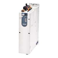
YASKAWA SGD7S-260D Manuals
Manuals and User Guides for YASKAWA SGD7S-260D. We have
1
YASKAWA SGD7S-260D manual available for free PDF download: Product Manual
YASKAWA SGD7S-260D Product Manual (603 pages)
Brand:
YASKAWA
| Category:
Servo Drives
| Size: 10.4 MB
Table of Contents
Table of Contents
24
Basic Information on
24
The Σ-7 Series
37
Introduction to Ethercat
38
Introduction to Canopen
38
Canopen over Ethercat OSI Model
38
Sending and Receiving Data in Ethercat (Coe) Communications
39
Coe Terminology
39
Data Types
40
Data Ranges
40
Interpreting the Nameplate
41
Part Names
42
Model Designations
44
Interpreting SERVOPACK Model Numbers
44
Interpreting Servomotor Model Numbers
45
Combinations of Servopacks and Servomotors
46
Combinations of Rotary Servomotors and Servopacks
46
Combinations of Linear Servomotors and Servopacks
47
Functions
48
Selecting a SERVOPACK
50
Ratings and Specifications
52
SERVOPACK Overload Protection Characteristics
52
Specifications
53
Block Diagrams
57
Servopacks Without Built-In Servomotor Brake Control
57
Servopacks with Built-In Servomotor Brake Control
60
External Dimensions
63
Front Cover Dimensions and Connector Specifications
63
SERVOPACK External Dimensions
65
SERVOPACK External Dimensions
66
Examples of Standard Connections between Servopacks and Peripheral Devices
67
SERVOPACK Installation
69
Installation Precautions
70
Mounting Types and Orientation
71
Mounting Hole Dimensions
72
Mounting Interval
73
Installing One SERVOPACK in a Control Panel
73
Installing more than One SERVOPACK in a Control Panel
73
Monitoring the Installation Environment
74
EMC Installation Conditions
75
Wiring and Connecting Servopacks
76
Wiring and Connecting Servopacks
78
General Precautions
78
Countermeasures against Noise
80
Grounding
83
Basic Wiring Diagrams
84
Wiring the Power Supply to the SERVOPACK
86
Terminal Symbols and Terminal Names
86
Connector Wiring Procedure
88
Power on Sequence
89
Power Supply Wiring Diagrams
90
Wiring Regenerative Resistors
93
Wiring DC Reactors
93
Wiring Servomotors
94
Terminal Symbols and Terminal Names
94
Pin Arrangement of Encoder Connector (CN2)
94
Wiring the SERVOPACK to the Encoder
95
Wiring the SERVOPACK to the Encoder
96
Wiring the SERVOPACK to the Holding Brake
100
Connecting I/O Signals
103
I/O Signal Connector (CN1) Names and Functions
103
I/O Signal Connector (CN1) Pin Arrangement
105
I/O Signal Wiring Examples
106
I/O Circuits
108
Connecting Safety Function Signals
110
Pin Arrangement of Safety Function Signals (CN8)
110
I/O Circuits
110
Connecting Dynamic Brake Resistors
112
Terminal Symbols and Terminal Names
112
Connecting a Dynamic Brake Resistor
112
Connecting Ethercat Communications Cables
114
Ethercat Connectors (RJ45)
114
Ethernet Communications Cables
115
Connecting the Other Connectors
116
Serial Communications Connector (CN3)
116
Computer Connector (CN7)
116
Analog Monitor Connector (CN5)
116
Manipulating SERVOPACK Parameters (Pn)
119
Classifications of SERVOPACK Parameters
119
Setting Methods for SERVOPACK Parameters
121
Write Prohibition Setting for SERVOPACK Parameters
123
Initializing SERVOPACK Parameter Settings
126
Power Supply Type Settings for the Main Circuit
128
Automatic Detection of Connected Motor
129
Motor Direction Setting
130
Setting the Linear Encoder Pitch
131
Writing Linear Servomotor Parameters
132
Selecting the Phase Sequence for a Linear Servomotor
136
Polarity Sensor Setting
138
Polarity Detection
139
Restrictions
139
Using the Servo on Command (Enable Operation Command) to Perform Polarity Detection
140
Using a Tool Function to Perform Polarity Detection
141
Overtravel and Related Settings
142
Overtravel Signals
142
Setting to Enable/Disable Overtravel
143
Motor Stopping Method for Overtravel
143
Overtravel Warnings
145
Overtravel Release Method Selection
146
Overtravel Status
147
Overtravel Operation by Mode
147
Holding Brake
148
Brake Operating Sequence
148
BK (Brake) Signal
148
BK (Brake) Signal
149
Output Timing of /BK (Brake) Signal When the Servomotor Is Stopped
150
Output Timing of /BK (Brake) Signal When the Servomotor Is Operating
150
Output Timing of /BK (Brake) Signal When the Servomotor Is Operating
151
Built-In Brake Relay Usage Selection
152
Motor Stopping Methods for Servo off and Alarms
153
Stopping Method for Servo off
154
Servomotor Stopping Method for Alarms
154
Motor Overload Detection Level
156
Detection Timing for Overload Warnings (A.910)
156
Detection Timing for Overload Warnings
156
Detection Timing for Overload Alarms (A.720)
157
Setting Unit Systems
158
Setting the Position Reference Unit
158
Setting the Speed Reference Unit
163
Resetting the Absolute Encoder
165
Precautions on Resetting
165
Applicable Tools
165
Operating Procedure
166
Setting the Origin of the Absolute Encoder
168
Absolute Encoder Origin Offset
168
Setting the Origin of the Absolute Linear Encoder
168
Setting the Regenerative Resistor Capacity
171
Setting the Energy Consumption and Resistance of the Dynamic Brake Resistor
172
Application Functions
173
I/O Signal Allocations
176
Input Signal Allocations
176
Output Signal Allocations
177
ALM (Servo Alarm) Signal
179
WARN (Warning) Signal
179
TGON (Rotation Detection) Signal
180
S-RDY (Servo Ready) Signal
180
V-CMP (Speed Coincidence Detection) Signal
181
COIN (Positioning Completion) Signal
182
NEAR (Near) Signal
183
Speed Limit During Torque Control
184
Operation for Momentary Power Interruptions
186
SEMI F47 Function
187
Setting the Motor Maximum Speed
189
Encoder Divided Pulse Output
190
Encoder Divided Pulse Output Signals
190
Setting for the Encoder Divided Pulse Output
195
Setting for the Encoder Divided Pulse Output
196
Software Limits
197
Selecting Torque Limits
198
Internal Torque Limits
198
External Torque Limits
199
CLT (Torque Limit Detection) Signal
202
Absolute Encoders
203
Connecting an Absolute Encoder
203
Structure of the Position Data of the Absolute Encoder
204
Output Ports for the Position Data from the Absolute Encoder
204
Reading the Position Data from the Absolute Encoder
205
Transmission Specifications
206
Calculating the Current Position in Machine Coordinates
207
Multiturn Limit Setting
208
Multiturn Limit Disagreement Alarm (A.CC0)
209
Absolute Linear Encoders
212
Connecting an Absolute Linear Encoder
212
Output Ports for the Position Data from the Absolute Linear Encoder
213
Linear Encoder
213
Reading the Position Data from the Absolute Linear Encoder
214
Transmission Specifications
214
Calculating the Current Position in Machine Coordinates
215
Software Reset
216
Preparations
216
Applicable Tools
216
Operating Procedure
217
Initializing the Vibration Detection Level
218
Preparations
218
Applicable Tools
218
Operating Procedure
219
Related Parameters
221
Adjusting the Motor Current Detection Signal Offset
222
Automatic Adjustment
222
Automatic Adjustment
224
Manual Adjustment
225
Forcing the Motor to Stop
227
FSTP (Forced Stop Input) Signal
227
Stopping Method Selection for Forced Stops
227
Resetting Method for Forced Stops
229
ZONE Outputs (FT64 Specification)
230
ZONE Table and ZONE Signals
230
ZONE Table Settings
231
ZONE Output Application Example
234
Trial Operation and Actual Operation
235
Flow of Trial Operation
236
Flow of Trial Operation for Rotary Servomotors
236
Flow of Trial Operation for Linear Servomotors
238
Inspections and Confirmations before Trial Operation
240
Trial Operation for the Servomotor Without a Load
241
Preparations
241
Applicable Tools
241
Operating Procedure
242
Trial Operation with Ethercat (Coe) Communications
244
Trial Operation with the Servomotor Connected to the Machine
245
Precautions
245
Preparations
245
Operating Procedure
246
Convenient Function to Use During Trial Operation
247
Program Jogging
247
Origin Search
253
Test Without a Motor
255
Monitoring
258
Tuning
259
Overview and Flow of Tuning
262
Tuning Functions
263
Diagnostic Tool
264
Monitoring Methods
265
Precautions to Ensure Safe Tuning
266
Overtravel Settings
266
Torque Limit Settings
266
Setting the Position Deviation Overflow Alarm Level
266
Vibration Detection Level Setting
268
Setting the Position Deviation Overflow Alarm Level at Servo on
269
Tuning-Less Function
270
Application Restrictions
270
Operating Procedure
271
Troubleshooting Alarms
272
Parameters Disabled by Tuning-Less Function
273
Automatically Adjusted Function Setting
273
Related Parameters
273
Estimating the Moment of Inertia
274
Outline
274
Restrictions
274
Applicable Tools
275
Operating Procedure
275
Autotuning Without Host Reference
281
Outline
281
Restrictions
282
Applicable Tools
283
Operating Procedure
283
Troubleshooting Problems in Autotuning Without a Host Reference
287
Automatically Adjusted Function Settings
289
Related Parameters
291
Autotuning with a Host Reference
292
Outline
292
Restrictions
293
Applicable Tools
293
Operating Procedure
294
Troubleshooting Problems in Autotuning with a Host Reference
297
Automatically Adjusted Function Settings
297
Related Parameters
298
Custom Tuning
299
Outline
299
Preparations
299
Applicable Tools
300
Operating Procedure
300
Automatically Adjusted Function Settings
306
Tuning Example for Tuning Mode 2 or 3
306
Related Parameters
307
Anti-Resonance Control Adjustment
308
Outline
308
Preparations
308
Applicable Tools
309
Operating Procedure
309
Related Parameters
311
Suppressing Different Vibration Frequencies with Anti-Resonance Control
311
Vibration Suppression
313
Outline
313
Preparations
314
Applicable Tools
314
Operating Procedure
314
Setting Combined Functions
316
Related Parameters
316
Speed Ripple Compensation
317
Outline
317
Setting up Speed Ripple Compensation
317
Setting Parameters
321
Additional Adjustment Functions
323
Gain Switching
323
Friction Compensation
326
Current Control Mode Selection
327
Current Gain Level Setting
328
Speed Detection Method Selection
328
Speed Feedback Filter
328
Backlash Compensation
329
Manual Tuning
334
Tuning the Servo Gains
334
Compatible Adjustment Functions
344
Diagnostic Tools
348
Mechanical Analysis
348
Easy FFT
350
Monitoring Product Information
355
Items that You Can Monitor
355
Operating Procedures
355
Monitoring SERVOPACK Status
356
Servo Drive Status
356
Monitoring Status and Operations
356
I/O Signal Monitor
358
Monitoring Machine Operation Status and Signal Waveforms
359
Items that You Can Monitor
359
Using the Sigmawin
360
Monitoring Machine Operation Status and Signal Waveforms
360
Using a Measuring Instrument
362
Monitoring Product Life
366
Items that You Can Monitor
366
Operating Procedure
367
Preventative Maintenance
368
Alarm Tracing
369
Data for Which Alarm Tracing Is Performed
369
Applicable Tools
369
Fully-Closed System
371
SERVOPACK Commissioning Procedure
372
Parameter and Object Settings for Fully-Closed Loop Control
374
Control Block Diagram for Fully-Closed Loop Control
374
External Absolute Encoder Data Reception
374
Setting the Motor Direction and the Machine Movement Direction
375
Setting the Number of External Encoder Scale Pitches
375
Setting the PAO, PBO, and PCO (Encoder Divided Pulse Output)
376
Signals
376
External Absolute Encoder Data Reception Sequence
377
Setting Unit Systems
377
Alarm Detection Settings
377
Sequence
377
Analog Monitor Signal Settings
378
Setting to Use an External Encoder for Speed Feedback
378
Monitoring an External Encoder
379
Option Module Required for Monitoring
379
Related Parameters
379
Block Diagrams
379
Introduction to the Safety Functions
382
Safety Functions
382
Precautions for Safety Functions
383
Hard Wire Base Block (HWBB and SBB)
384
Risk Assessment
384
Hard Wire Base Block (HWBB) State
385
Resetting the HWBB State
386
Recovery Method
387
Detecting Errors in HWBB Signal
387
HWBB Input Signal Specifications
388
Operation Without a Host Controller
388
S-RDY (Servo Ready Output) Signal
389
BK (Brake Output) Signal
389
Stopping Methods
390
ALM (Servo Alarm) Signal
390
EDM1 (External Device Monitor)
391
EDM1 Output Signal Specifications
391
Applications Examples for Safety Functions
392
Connection Example
392
Failure Detection Method
392
Procedure
393
Validating Safety Functions
394
Connecting a Safety Function Device
395
Ethercat Communications
396
Ethercat Slave Information
397
Ethercat State Machine
398
Ethercat (Coe) Communications Settings
400
Normal Device Recognition Process at Startup
400
Application Example
400
Device Recognition with Station Aliases
400
PDO Mappings
401
Setting Procedure for PDO Mappings
402
Default PDO Mappings
402
Synchronization with Distributed Clocks
403
Emergency Messages
406
Cia402 Drive Profile
407
Device Control
409
State Machine Control Commands
410
Bits in Statusword (6041 Hex)
410
Related Objects
410
Modes of Operation
411
Related Objects
411
Dynamic Mode Changes
411
Position Control Modes
412
Profile Position Mode
412
Profile Position Mode
413
Interpolated Position Mode
415
Cyclic Synchronous Position Mode
418
Cyclic Synchronous Position Mode
419
Homing
420
Related Objects
420
Homing Method (6098 Hex)
420
Velocity Control Modes
423
Profile Velocity Mode
423
Cyclic Synchronous Velocity Mode
424
Torque Control Modes
425
Profile Torque Mode
425
Cyclic Sync Torque Mode
426
Torque Limits
427
Digital I/O Signals
428
Touch Probe
429
Related Objects
429
Example of Execution Procedure for a Touch Probe
430
Fully-Closed Loop Control
431
Object Dictionary
432
Object Dictionary List
434
General Objects
436
PDO Mapping Objects
440
Sync Manager Communications Objects
444
Manufacturer-Specific Objects
448
Device Control
452
Profile Position Mode
460
Homing Mode
462
Position Control Function
464
Interpolated Position Mode
466
Cyclic Synchronous Position Mode
472
Profile Velocity/Cyclic Synchronous Velocity Mode
473
Profile Torque/Cyclic Synchronous Torque Mode
474
Torque Limit Function
475
Touch Probe Function
476
Dual Encoder Feedback
480
Maintenance
481
Inspections and Part Replacement
482
Inspections
482
Guidelines for Part Replacement
482
Replacing the Battery
483
Alarm Displays
485
List of Alarms
485
Troubleshooting Alarms
491
Resetting Alarms
519
Displaying the Alarm History
520
Clearing the Alarm History
521
Resetting Alarms Detected in Option Modules
522
Resetting Motor Type Alarms
523
Warning Displays
525
List of Warnings
525
Troubleshooting Warnings
526
Troubleshooting Based on the Operation and Conditions of the Servomotor
531
Parameter and Object Lists
542
Appendices
589
Advertisement
Advertisement
Related Products
YASKAWA SGD7S-200A
YASKAWA SGD7S-2R8F
YASKAWA SGD7S-****20A Series
YASKAWA SGD7S-2R8F20A023F40B
YASKAWA SGD7S-200A20A023F40B
YASKAWA SGD7S-2R8F20A000F41B
YASKAWA SGD7S-2R1F20A000F41B
YASKAWA Sigma-7 SGD7S-20A F84 Series
YASKAWA SGD7S-2R1F20A023F40B
YASKAWA SGD7S-2R8A
YASKAWA Categories
Controller
DC Drives
Servo Drives
Robotics
Inverter
More YASKAWA Manuals
Login
Sign In
OR
Sign in with Facebook
Sign in with Google
Upload manual
Upload from disk
Upload from URL