Sign In
Upload
Manuals
Brands
Teledyne Manuals
Test Equipment
T3DSO1000
Teledyne T3DSO1000 Manuals
Manuals and User Guides for Teledyne T3DSO1000. We have
3
Teledyne T3DSO1000 manuals available for free PDF download: Programming Manual, User Manual
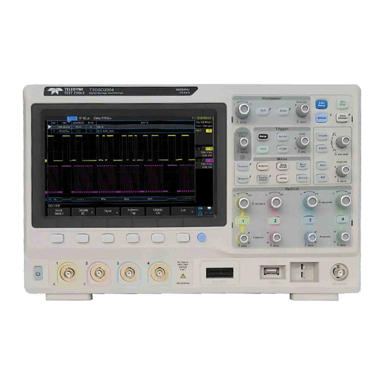
Teledyne T3DSO1000 User Manual (227 pages)
Digital Oscilloscope
Brand:
Teledyne
| Category:
Test Equipment
| Size: 3.54 MB
Table of Contents
Safety Information
3
Safety Terms and Symbols
5
Measurement Category
6
Working Environment
7
Ventilation Requirement
8
General Care and Cleaning
9
Document Overview
10
Table of Contents
11
Quick Start
19
General Inspection
20
Appearance and Dimensions
21
To Prepare the Oscilloscope for Use
23
To Adjust the Supporting Legs
23
To Connect to Power Supply
24
Power-On Inspection
25
To Connect the Probe
25
Function Inspection
26
Probe Compensation
27
Front Panel Overview
28
Rear Panel Overview
30
Front Panel Function Overview
32
Horizontal
32
Vertical
33
Trigger
34
Run Control
35
Universal Knob
36
Menu
37
Help
39
User Interface
40
To Use the Security Lock
42
To Set the Vertical System
43
To Enable the Channel
44
To Adjust the Vertical Scale
45
To Adjust the Vertical Position
45
To Specify Bandwidth Limit
46
To Specify Channel Coupling
46
To Specify Channel Input Impedance
47
To Specify Probe A�Enuation Factor
47
To Invert a Waveform
48
To Specify Amplitude Unit
48
To Specify Deskew
48
Set the Horizontal System
49
Adjust the Horizontal Scale
50
Adjust Trigger Delay
51
Set the Roll Mode
52
Use the Zoom Function
53
To Set the Sample System
54
Run Control
55
Overview of Sampling
56
Sampling Theory
56
Sample Rate
57
Oscilloscope Bandwidth and Sample Rate
58
Select Memory Depth
59
Select Sampling Mode
60
Select Waveform Interpolam on Method
61
Normal
63
Select Acquisition Mode
63
Peak Detect
64
Average
65
High Resolum on
66
Change the Horizontal Format
67
Use Sequence Mode
68
To Trigger the Oscilloscope
70
Trigger Source
72
Trigger Mode
73
Trigger Level
74
Trigger Coupling
75
Trigger Holdoff
76
Noise Rejection
77
Trigger Type
79
Edge Trigger
80
Slope Trigger
81
Pulse Trigger
83
Video Trigger
85
Window Trigger
88
Interval Trigger
91
Dropout Trigger
93
Runt Trigger
95
Pattern Trigger
97
Serial Trigger and Decode
99
I2C Trigger and Serial Decode
100
Setup for I2C Signals
100
I2C Triggering
102
I2C Serial Decode
106
SPI Triggering and Serial Decode
108
Setup for SPI Signals
108
SPI Triggering
111
SPI Serial Decode
113
UART/RS232 Triggering and Serial Decode
115
Setup for UART/RS232 Signals
115
UART/RS232 Triggering
117
UART/RS232 Serial Decode
119
CAN Trigger and Serial Decode
121
Setup for CAN Signals
121
CAN Triggering
123
CAN Serial Decode
125
LIN Triggering and Serial Decode
127
Setup for LIN Signals
127
LIN Triggering
128
LIN Serial Decode
130
To Save Reference Waveform
132
To Save REF Waveform to Internal Memory
133
To Display REF Waveform
133
To Adjust REF Waveform Display
134
To Clear REF Waveform Display
135
To Make Math Operation
136
Units for Math Waveforms
136
Math Operators
137
Addition or Subtraction
137
Multiplication and Division
138
FFT Operation
139
Math Function Operation
142
Differentiate
142
Integrate
143
Square Root
144
Cursors
146
To Make Cursors Measurements
146
Y Cursors
146
To Make Cursor Measurements
147
To Make Measurements
148
Type of Measurement
149
Voltage Measurements
149
Time Measurements
151
Delay Measurements
152
To Make Automatic Measurement
153
To Clear Measurement Parameters
155
To Make All Measurement
155
Display Setting
156
To Set Display Type
157
To Set Color Display
158
To Set and Clear Persistence
158
To Clear the Display
159
To Adjust Waveform Intensity
160
To Select Grid Type
160
To Adjust Grid Brightness
161
To Adjust Transparence
161
Save and Recall
162
Save Type
163
Internal Save and Recall
165
External Save and Recall
166
Disk Management
169
To Create a New File or Folder
170
To Delete a File or Folder
171
Digital Channels(Option)
172
To Connect the Digital Probes to the Device-Under-Test
173
Acquiring Waveform Using the Digital Channels
174
To Change the Display Type of the Digital Channels
174
To Switch a Single Channel on or off
175
To Switch All Digital Channels on or off
175
To Change the Logic Threshold for Digital Channels
176
To Reposition a Digital Channel
176
To Display Digital Channels as a Bus
177
System Function Setting
178
To View the System Status
179
To Do Self Calibration
180
To Enable or Disable the Sound
181
To Specify the Language
181
To Do Pass/Fail T Est
182
To Set and Perform Pass/Fail Test
183
To Save and Recall Test Mask
184
Arbitrary Waveform Generator(Opm On)
186
Output
187
Setting
187
Systems
191
Remove Device
192
IO Set
193
To Set the USB Device
193
To Set the LAN
194
To Set the WLAN (Option)
195
To Set aux Output
196
To Use the Web Server
197
To Update Firmware and Configuration
198
Do Self Test
199
Screen Test
199
Keyboard Test
200
LED Test
201
To Specify Screen Saver Time
202
To Use the Expand Setting
203
To Use the Power on Line
203
Option Management
204
Search
206
Setting
206
Results
208
Navigate
209
Time Navigate
209
History Frame Navigate
209
Search Event Navigate
209
Bode Plot
210
Perform Bode Plot Applicam on
211
Setting
211
To Use the History Function
214
Factory Setup
216
Troubleshooting
220
Cer�Fica�Ons
222
Advertisement
Teledyne T3DSO1000 User Manual (223 pages)
Digital Oscilloscope
Brand:
Teledyne
| Category:
Test Equipment
| Size: 2.88 MB
Table of Contents
Safety Information
3
Safety Terms and Symbols
5
Measurement Category
6
Working Environment
7
Ventilation Requirement
8
General Care and Cleaning
9
Document Overview
10
Table of Contents
11
Quick Start
20
General Inspection
21
Appearance and Dimensions
22
To Prepare the Oscilloscope for Use
24
To Adjust the Supporting Legs
24
To Connect to Power Supply
25
Power-On Inspection
26
To Connect the Probe
26
Function Inspection
27
Probe Compensation
28
Front Panel Overview
29
Rear Panel Overview
31
Front Panel Function Overview
33
Horizontal
33
Vertical
34
Trigger
35
Run Control
36
Universal Knob
37
Menu
38
Help
40
User Interface
41
To Use the Security Lock
43
To Set the Vertical System
44
To Enable the Channel
45
To Adjust the Vertical Scale
46
To Adjust the Vertical Position
46
To Specify Channel Coupling
47
To Specify Bandwidth Limit
47
To Specify Probe Attenuation Factor
48
To Specify Channel Input Impedance
48
To Specify Amplitude Unit
49
To Specify Deskew
49
To Invert a Waveform
49
Set the Horizontal System
50
Adjust the Horizontal Scale
51
Adjust Trigger Delay
52
Set the Roll Mode
53
Use the Zoom Function
54
To Set the Sample System
55
Run Control
56
Overview of Sampling
57
Sampling Theory
57
Sample Rate
58
Oscilloscope Bandwidth and Sample Rate
59
Select Memory Depth
60
Select Sampling Mode
61
Select Waveform Interpolation Method
62
Select Acquisition Mode
64
Normal
64
Peak Detect
65
Average
66
High Resolution
67
Change the Horizontal Format
68
Use Sequence Mode
69
To Trigger the Oscilloscope
71
Trigger Source
73
Trigger Mode
74
Trigger Level
75
Trigger Coupling
76
Trigger Holdoff
77
Noise Rejection
78
Trigger Type
80
Edge Trigger
81
Slope Trigger
82
Pulse Trigger
84
Video Trigger
86
Window Trigger
89
Interval Trigger
92
Dropout Trigger
94
Runt Trigger
96
Pattern Trigger
98
Serial Trigger and Decode
100
I2C Trigger and Serial Decode
101
Setup for I2C Signals
101
I2C Triggering
103
I2C Serial Decode
107
SPI Triggering and Serial Decode
109
Setup for SPI Signals
109
SPI Triggering
112
SPI Serial Decode
114
UART/RS232 Triggering and Serial Decode
116
Setup for UART/RS232 Signals
116
UART/RS232 Triggering
118
UART/RS232 Serial Decode
120
CAN Trigger and Serial Decode
122
Setup for CAN Signals
122
CAN Triggering
124
CAN Serial Decode
126
LIN Triggering and Serial Decode
128
Setup for LIN Signals
128
LIN Triggering
129
LIN Serial Decode
131
To Save Reference Waveform
133
To Save REF Waveform to Internal Memory
134
To Display REF Waveform
134
To Adjust REF Waveform Display
135
To Clear REF Waveform Display
136
To Make Math Operation
137
Units for Math Waveforms
137
Math Operators
138
Addition or Subtraction
138
Multiplication and Division
139
FFT Operation
140
Math Function Operation
143
Differentiate
143
Integrate
144
Square Root
145
To Make Cursors Measurements
147
Cursors
147
Y Cursors
147
To Make Cursor Measurements
148
To Make Measurements
149
Type of Measurement
150
Voltage Measurements
150
Time Measurements
152
Delay Measurements
153
To Make Automatic Measurement
154
To Clear Measurement Parameters
156
To Make All Measurement
156
Display Setting
157
To Set Display Type
158
To Set Color Display
159
To Set and Clear Persistence
159
To Clear the Display
160
To Select Grid Type
161
To Adjust Waveform Intensity
161
To Adjust Grid Brightness
162
To Adjust Transparence
162
Save and Recall
163
Save Type
164
Internal Save and Recall
166
External Save and Recall
167
Disk Management
170
To Create a New File or Folder
171
To Delete a File or Folder
172
Digital Channels(Option)
173
To Connect the Digital Probes to the Device-Under-Test
174
Acquiring Waveform Using the Digital Channels
175
To Change the Display Type of the Digital Channels
175
To Switch a Single Channel on or off
176
To Switch All Digital Channels on or off
176
To Change the Logic Threshold for Digital Channels
177
To Reposition a Digital Channel
177
To Display Digital Channels as a Bus
178
System Function Setting
179
To View the System Status
180
To Do Self Calibration
181
To Enable or Disable the Sound
182
To Specify the Language
182
To Do Pass/Fail Test
183
To Set and Perform Pass/Fail Test
184
To Save and Recall Test Mask
185
Arbitrary Waveform Generator(Option)
187
Output
188
Setting
190
Systems
192
Remove Device
193
IO Set
194
To Set the USB Device
194
To Set the LAN
195
To Set the WLAN (Option)
196
To Set Aux Output
197
To Use the Web Server
198
To Update Firmware and Configuration
199
Do Self Test
200
Screen Test
200
Keyboard Test
201
LED Test
202
To Specify Screen Saver Time
203
To Use the Expand Setting
204
To Use the Power on Line
204
Option Management
205
Search
207
Setting
207
Results
209
Navigate
210
Time Navigate
210
History Frame Navigate
210
Search Event Navigate
210
Bode Plot
211
Perform Bode Plot Application
212
Setting
212
To Use the History Function
215
Factory Setup
217
Troubleshooting
221
Teledyne T3DSO1000 Programming Manual (233 pages)
Digital Oscilloscopes
Brand:
Teledyne
| Category:
Test Equipment
| Size: 1.92 MB
Table of Contents
Table of Contents
3
Programming Overview
6
Establishing Communications
6
Install NI-VISA
6
Connect the Instrument
10
Remote Control
11
User-Defined Programming
11
Send SCPI Commands Via NI-MAX
11
Using SCPI with Telnet
11
Using SCPI with Sockets
13
Introduction to the SCPI Language
14
About Commands & Queries
14
Description
14
Usage
14
Command Notation
15
Commands & Queries
17
COMMON (*) Commands
18
COMM_HEADER Commands
22
ACQUIRE Commands
24
AUTOSET Commands
38
CHANNEL Commands
40
CURSOR Commands
50
DIGITAL Commands
58
DISPLAY Commands
68
HISTORY Commands
74
MATH Commands
79
MEASURE Commands
96
PASS/FAIL Commands
110
PRINT Commands
122
RECALL Commands
124
REFERENCE Commands
128
SAVE Commands
138
STATUS Commands
145
SYSTEM Commands
148
TIMEBASE Commands
153
TRIGGER Commands
161
WAVEFORM Commands
178
WGEN Commands
192
Programming Examples
199
VISA Examples
200
VC++ Example
200
VB Example
207
MATLAB Example
213
Labview Example
215
C# Example
218
Examples of Using Sockets
221
Python Example
221
C Example
224
Common Command Examples
226
Read Waveform Data (WF) Example
226
Advertisement
Advertisement
Related Products
Teledyne T3DSO1000A Series
Teledyne T3DSO1102
Teledyne T3DSO1204
Teledyne T3DSO1104
Teledyne T3DSO2000
Teledyne LeCroy T3DSO2000A Series
Teledyne LeCroy T3DSO2502A
Teledyne LeCroy T3DSO2354A
Teledyne LeCroy T3DSO2104A
Teledyne T3DSO2304
Teledyne Categories
Measuring Instruments
Analytical Instruments
Digital Camera
Test Equipment
Laboratory Equipment
More Teledyne Manuals
Login
Sign In
OR
Sign in with Facebook
Sign in with Google
Upload manual
Upload from disk
Upload from URL