Sign In
Upload
Manuals
Brands
IBM Manuals
Storage
SAN Volume Controller
User Manuals: IBM SAN Volume Controller Storage System
Manuals and User Guides for IBM SAN Volume Controller Storage System. We have
1
IBM SAN Volume Controller Storage System manual available for free PDF download: Hardware Maintenance Manual
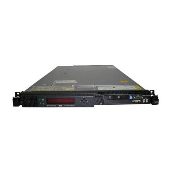
IBM SAN Volume Controller Hardware Maintenance Manual (334 pages)
System Storage SAN Volume Controller
Brand:
IBM
| Category:
Storage
| Size: 40 MB
Table of Contents
Table of Contents
5
Figures
7
General Safety
15
Electrical Safety
16
Safety and Environmental Notices
15
Inspecting the SAN Volume Controller for Unsafe Conditions
17
External Device Check
18
Internal Device Checks
18
Checking the Grounding of SAN Volume Controller, the Uninterruptible Power Supply, and the Redundant Ac-Power Switch
18
Inspecting the Uninterruptible Power Supply for Unsafe Conditions
20
Uninterruptible Power-Supply Requirements
20
Emergency Power-Off Shutdown
21
Environmental Notices and Statements
21
Product Recycling and Disposal
21
Handling Static-Sensitive Devices
21
About this Guide
23
Emphasis
23
SAN Volume Controller Library and Related Publications
23
Other IBM Publications
24
IBM Documentation and Related Websites
24
Summary of Changes
23
Who Should Use this Guide
23
How to Order IBM Publications
25
Related Web Sites
25
Sending Your Comments
25
Chapter 1. Parts Listing
27
SAN Volume Controller 2145-CF8 Parts
27
Exploded View of the SAN Volume Controller 2145-CF8 Node
28
Power-Control Button
29
Frus in the SAN Volume Controller 2145-CF8 Parts Assembly
29
Disk Controller
30
Operator-Information Panel
30
Board
30
SAN Volume Controller 2145-8A4 Parts
31
Frus to Which SAN Volume Controller 2145-CF8 Service Procedures Do Not Refer
31
Pluggable (SFP) Transceiver Feature
31
Exploded View of the SAN Volume Controller 2145-8A4 Node
32
Frus that Are Exchanged Within SAN Volume
32
Controller 2145-8A4 Service Procedures
32
Frus that Are Exchanged Within SAN Volume Controller 2145-8A4 Service Procedures
33
SAN Volume Controller 2145-8G4 Parts
34
The SAN Volume Controller 2145-8A4
34
Frus that Are Not Exchanged Within SAN Volume Controller 2145-8A4 Service Procedures
34
Exploded View of the SAN Volume Controller 2145-8G4 Node
35
Distinctive Characteristics of the SAN Volume
35
Distinctive Characteristics of the SAN Volume Controller 2145-8G4 Versions
36
FRU Part Numbers that Are Unique for the SAN Volume Controller 2145-8G4 Rev 1 Version
36
FRU Part Numbers that Are Unique for the SAN Volume Controller 2145-8G4 Rev 2 Version
36
Frus in the SAN Volume Controller 2145-8G4 Parts Assembly
36
Frus that Are Not Referenced by SAN Volume Controller 2145-8G4 Service Procedures
37
SAN Volume Controller 2145-8F4 Parts
38
Exploded View of the SAN Volume Controller 2145-8F4 Node
38
SAN Volume Controller 2145-8F2 Parts
39
SAN Volume Controller 2145-8F4 Frame
39
Items Not Included in the SAN Volume Controller 2145-8F4 Frame Assembly
39
Exploded View of the SAN Volume Controller 2145-8F2 Node
40
SAN Volume Controller 2145-8F2 Frame Assembly
40
Items Not Included in the SAN Volume Controller 2145-8F2 Frame Assembly
41
Redundant Ac-Power Switch Parts
42
2145 UPS-1U Parts
42
View of the Redundant Ac-Power Switch FRU
42
Power Cables for the 2145 UPS-1U
43
Exploded View of the 2145 UPS-1U Hardware
43
UPS-1U Part Numbers
43
Chapter 2. Removing and Replacing Parts
45
Enabling Concurrent Maintenance
45
Preparing to Remove and Replace Parts
46
Working Inside the Node with the Power on
46
Removing and Replacing SAN Volume Controller Parts
46
Removing the Cable-Management Arm
46
SAN Volume Controller 2145-CF8
47
Cable-Management Arm and Associated Parts
47
SAN Volume Controller 2145-CF8 Release Latches and Mounting Screws
48
SAN Volume Controller 2145-CF8 Cables in the Cable-Management Arm
48
SAN Volume Controller 2145-CF8 Cable-Management Arm on the Support Arm
49
Removing the SAN Volume Controller 2145-CF8 Cable-Management Arm Mounting Bracket
50
Freeing the Swing End of the SAN Volume
50
Replacing the Cable-Management Arm
51
Removing the SAN Volume Controller 2145-CF8 Cable-Management Stop Bracket
51
Detaching the SAN Volume Controller 2145-CF8 Cable-Management Support Arm
51
Rack Rear: Attaching the SAN Volume
52
Rack Rear: Installing the SAN Volume
52
Attaching the Free End of the SAN Volume
52
Rack Rear: Installing the SAN Volume
53
SAN Volume Controller 2145-CF8 Cable-Management Arm on the Support Arm
54
Removing the Cable-Retention Bracket
55
SAN Volume Controller 2145-CF8 Cables in the Cable-Management Arm
55
SAN Volume Controller 2145-CF8 Cable-Retention Brackets
56
SAN Volume Controller 2145-8A4 with the Cable-Retention Bracket Installed
57
SAN Volume Controller 2145-8G4 Cable Retention Bracket - Type a
58
SAN Volume Controller 2145-8G4 Cable Retention Bracket - Type B
58
Controller 2145-8G4
58
The SAN Volume Controller 2145-8G4 with the Cable-Retention Bracket Attached
59
Replacing the Cable-Retention Bracket
60
The SAN Volume Controller 2145-8G4 with
60
SAN Volume Controller 2145-CF8 Cable-Retention Brackets
61
Raising the SAN Volume Controller 2145-CF8 Locking Levers of the Slide Rails of the Rack
62
Retaining Screw on the SAN Volume Controller 2145-8A4 Node
62
Installing the SAN Volume Controller 2145-8A4 Cable Retention Bracket
63
SAN Volume Controller 2145-8G4 Cable Retention Bracket - Type a
64
SAN Volume Controller 2145-8G4 Cable Retention Bracket - Type B
64
The SAN Volume Controller 2145-8G4 before You Attach the Cable-Retention Bracket
65
Removing the SAN Volume Controller from a Rack
66
The SAN Volume Controller 2145-8G4 with
66
Attaching the Cable Retention Bracket to the SAN Volume Controller 2145-8F4 Power Cable
66
Removing the SAN Volume Controller 2145-CF8 from the Rack
69
The Captive Thumbscrews that Secure the Node and the Shipping Brackets
71
Removing the SAN Volume Controller 2145-8G4 from the Rack
73
Replacing the SAN Volume Controller in a Rack
74
Installing the SAN Volume Controller 2145-CF8 Node in the Slide Rails of the Rack
77
Raising the SAN Volume Controller 2145-CF8 Locking Levers of the Slide Rails of the Rack
77
The Captive Thumbscrews that Secure the Node and the Shipping Brackets
78
Mounting Flange
78
The Captive Thumbscrews that Secure the Node and the Shipping Brackets
79
Aligning the SAN Volume Controller 2145-8G4 with the Rack Slides
79
Removing the Support Rails for a SAN Volume Controller
80
Sliding the SAN Volume Controller 2145-8F4
80
Disengaging the SAN Volume Controller 2145-CF8 Slide Rails from the Rear of the Rack
81
Removing the SAN Volume Controller 2145-CF8 Slide Rails from the Rack
81
Controller 2145-CF8
81
The Rail-Adjustment Bracket and the Release Tab
82
Removing the Latch Strike from the Front of the Slide Rail
83
Removing the Right Slide Rail from the Front of the Rack
83
Installing the Support Rails for a SAN Volume Controller
84
The Left Support Rail for the SAN Volume
84
Volume Controller 2145-CF8 Node
84
Installing the SAN Volume Controller 2145-CF8 Slide Rails on the Rack
85
Installing the Rear of a SAN Volume Controller 2145-CF8 Slide Rail in the Rear of the Rack
85
Installing the Front of a SAN Volume Controller 2145-CF8 Slide Rail in the Front of the Rack
86
SAN Volume Controller 2145-8A4 Support-Rails Installation Kit
86
A Closed Rail-Locking Carrier at the Front of the
87
An Open Rail-Locking Carrier at the Rear of the
88
Aligning the Pins on the Left Front Support Rail
89
SAN Volume Controller 2145-8G4 Support Rails Installation Kit
90
Inserting the Right Slide Rail into the Rear Rack
90
Extending the Right Slide Rail
91
Attaching the Latch Strike to the Front of the Slide Rail
91
Retracting the Latch-Lock Carrier
92
Opening the Front Latch-Lock Carrier Assembly
92
Opening the Back Latch-Lock Carrier Assembly
93
Installing the Front End of the Rail
93
Removing the Top Cover
94
Closing the Latch-Lock Carrier Assembly
94
Removing the SAN Volume Controller 2145-CF8 Cover
95
Removing the SAN Volume Controller 2145-8A4 Cover
96
The SAN Volume Controller 2145-8G4 with Fan Door Open
97
Replacing the Top Cover
98
SAN Volume Controller 2145-8F2 or SAN Volume Controller 2145-8F4 with Fan Doors Open
98
Replacing the SAN Volume Controller 2145-CF8 Cover
99
Raising the SAN Volume Controller 2145-CF8
99
SAN Volume Controller 2145-8G4 with the Fan
100
Removing the Service Controller
101
SAN Volume Controller 2145-8F2 with the
101
Left Release Button of a SAN Volume
103
Service Controller for the SAN Volume
103
SAN Volume Controller 2145-CF8 Service
104
Removing and Replacing the USB Cable in the SAN Volume Controller 2145-CF8 Service
105
USB Service-Controller Cable Connected to the Disk Controller and USB Riser Card in the SAN Volume Controller 2145-CF8
106
USB Service-Controller Cable Connected to the
106
USB Service-Controller Cable Connector on the
107
SAN Volume Controller 2145-8A4 Service
108
Controller 2145-8G4
108
SAN Volume Controller 2145-8G4 Service
109
Removing the Service Controller from the SAN
109
SAN Volume Controller 2145-8F2 or SAN
110
Replacing the Service Controller
111
SAN Volume Controller 2145-8F2 or SAN
111
Raising the SAN Volume Controller 2145-CF8
113
SAN Volume Controller 2145-8A4 Service
114
SAN Volume Controller 2145-8G4 Service
115
SAN Volume Controller 2145-8F2 or SAN
117
Replacing a Disk Drive and a Service Controller on the SAN Volume Controller
118
Removing and Replacing the SAN Volume Controller Power-Cable Assembly
118
Power LED on the SAN Volume Controller
119
Removing the Memory Modules (DIMM)
120
SAN Volume Controller Models 2145-CF8
120
Locating the SAN Volume Controller 2145-CF8
121
Locating the SAN Volume Controller 2145-8A4
122
Locating the SAN Volume Controller 2145-8G4
122
Memory Modules
123
Locating the SAN Volume Controller 2145-8F2
123
Replacing the Memory Modules (DIMM)
124
Removing the Memory Modules
124
Removing the Disk Drive
125
Replacing a Memory Module
125
For the SAN Volume Controller 2145-CF8
125
SAN Volume Controller 2145-8A4 SATA Disk
126
2145-8F4
126
Drive
127
SAN Volume Controller 2145-4F2 Disk Drive
128
Attaching the Rails to the SAN Volume
128
Volume Controller 2145-CF8
129
Boot Drive for the SAN Volume Controller
130
Drive-Bay Filler Panel and Disk-Drive Handle
130
Drive Ids for SAN Volume Controller
131
Removing the SATA Disk Drive
131
SAN Volume Controller 2145-8A4 SATA Disk
132
Replacing the Disk Drive
133
Removing the SATA Disk Drive
133
Drive-Bay Filler Panel and Disk-Drive Handle
134
Raising the SAN Volume Controller 2145-CF8
135
2145-8G4
135
Attaching the Rails Assembly to the SATA Disk Drive for the SAN Volume Controller 2145-8A4 and the SAN Volume Controller 2145-8G4
136
Removing a Solid-State Drive (SSD)
137
Service Controller for the SAN Volume Controller 2145-CF8 with Attached USB Cable
138
Replacing a Solid-State Drive (SSD)
139
Solid-State Drive (SSD) for the SAN Volume Controller 2145-CF8
139
SAN Volume Controller 2145-CF8 Drive and Drive-Bay Filler
140
Removing the Disk-Drive Backplane
141
Raising the SAN Volume Controller 2145-CF8
141
Boot-Disk SAS Cable and the High-Speed SAS
142
The SAN Volume Controller 2145-CF8 Disk
143
SAN Volume Controller 2145-8A4 SATA Cable Connectors
144
Air Deflector for the SAN Volume Controller
144
Board
144
SAN Volume Controller 2145-8A4 Power Supply Connectors
145
The SAN Volume Controller 2145-8G4
146
The SAN Volume Controller 2145-8G4 SATA
146
Replacing the Disk-Drive Backplane
147
The SAN Volume Controller 2145-CF8 Disk
147
Boot-Disk SAS Cable and the High-Speed SAS Cable Connected to the Disk Backplane in the SAN Volume Controller 2145-CF8
148
SAN Volume Controller 2145-CF8
149
Boot-Disk SAS Cable Routed through the Blue Bulkhead Clip and Connected to the SAS Disk Controller in the SAN Volume Controller
149
Raising the SAN Volume Controller 2145-CF8 Locking Levers of the Slide Rails of the Rack
150
Air Deflector for the SAN Volume Controller
150
SAN Volume Controller 2145-8A4 Power
151
SAN Volume Controller 2145-8A4 SATA Cables
152
The SAN Volume Controller 2145-8G4 SATA
153
The SAN Volume Controller 2145-8G4
153
Removing the CMOS Battery
154
Location of the SAN Volume Controller 2145-CF8 CMOS Battery Holder
155
SAN Volume Controller 2145-CF8 CMOS
155
Locating the SAN Volume Controller
156
Removing the SAN Volume Controller 2145-8A4 CMOS Battery
157
Location of the SAN Volume Controller 2145-8G4 CMOS Battery Holder
158
SAN Volume Controller 2145-8G4 CMOS Battery Holder
158
Location of the CMOS Battery on the SAN
159
Replacing the CMOS Battery
160
SAN Volume Controller 2145-8F2 or the SAN
160
Location of the SAN Volume Controller 2145-CF8 CMOS Battery Holder
161
SAN Volume Controller 2145-CF8 CMOS
161
Raising the SAN Volume Controller 2145-CF8 Locking Levers of the Slide Rails of the Rack
162
Locating the SAN Volume Controller
163
Installing the SAN Volume Controller 2145-8A4 CMOS Battery
163
Location of the SAN Volume Controller 2145-8G4 CMOS Battery Holder
164
SAN Volume Controller 2145-8G4 CMOS Battery Holder
165
Removing the Power Supply
166
Location of the CMOS Battery on the SAN Volume Controller 2145-8F2 or the SAN Volume Controller 2145-8F4
166
CMOS Battery Socket
166
SAN Volume Controller 2145-CF8 Power
168
SATA Connectors on the SAN Volume
169
Power P5 Connector on the SAN Volume
170
The Retention Clip for the SAN Volume
170
The SAN Volume Controller 2145-8A4
171
SAN Volume Controller 2145-8G4 Power Supply
171
Replacing the Power Supply
172
Removing the SAN Volume Controller 2145-8F2 Power Supply
172
SAN Volume Controller 2145-8F2 or SAN
172
Controller 2145-CF8
173
SAN Volume Controller 2145-CF8 Power
174
SAN Volume Controller 2145-CF8 Ac, DC, and
175
Air Deflector for the SAN Volume Controller
175
SATA Connectors on the SAN Volume
176
The Retention Clip for the SAN Volume
177
SAN Volume Controller 2145-8G4 Power Supply
178
2145-8A4 Power Supply
179
SAN Volume Controller 2145-8G4 Ac and DC
179
SAN Volume Controller 2145-8F2 Power Supply
179
Removing the Power Backplane
180
SAN Volume Controller 2145-8F2 or SAN Volume Controller 2145-8F4 Ac and DC Power Leds
180
SAN Volume Controller 2145-8G4 Power Backplane
181
Replacing the Power Backplane
182
SAN Volume Controller 2145-8F4 or SAN Volume Controller 2145-8F2 Power Backplane
182
SAN Volume Controller 2145-8G4 Power Backplane
183
Removing and Replacing the Frame Assembly
184
Replacing the SAN Volume Controller 2145-8F4 or SAN Volume Controller 2145-8F2 Power Backplane
184
Removing and Replacing the Fibre-Channel SFP Transceiver on a SAN Volume Controller Node
186
Instructions for Removing the SFP Transceiver
186
Removing the Fibre-Channel Adapter Assembly
187
Fibre-Channel SFP Transceiver
187
Connectors on the Rear of the SAN Volume Controller 2145-CF8
187
The SAN Volume Controller 2145-CF8
189
Removing the Fibre-Channel Riser-Card
189
SAN Volume Controller 2145-8A4 Riser-Card
190
Assembly
191
The Physical Port Numbers for the SAN Volume Controller 2145-8G4
191
Removing the Riser-Card Assembly from the SAN Volume Controller 2145-8G4
191
Rear View of the SAN Volume Controller
192
SAN Volume Controller 2145-8F2 Riser Card
193
Replacing the Fibre-Channel Adapter Assembly
194
SAN Volume Controller 2145-8F2 or SAN Volume Controller 2145-8F4 Slot 2 Adapter
194
Replacing the Riser-Card Assembly for the SAN Volume Controller 2145-8G4
195
The SAN Volume Controller 2145-CF8
195
System Board
195
SAN Volume Controller 2145-8A4 Riser-Card
196
Assembly
196
SAN Volume Controller 2145-8F2 or SAN
197
Replacing the Riser-Card Assembly for the SAN Volume Controller 2145-8G4
197
Removing the High-Speed SAS Adapter
198
Replacing the High-Speed SAS Adapter
199
High-Speed SAS Adapter Assembly Mounted in the Back Rail of the SAN Volume Controller
199
Removing the High-Speed SAS Riser-Card Assembly for the SAN Volume Controller
199
Replacing the High-Speed SAS Riser-Card Assembly for the SAN Volume Controller
200
System Board
200
Removing the High-Speed SAS Adapter, the Adapter Cable, and the Solid-State Drive (SSD)
201
High-Speed SAS Adapter Assembly Mounted in the Back Rail of the SAN Volume Controller
201
High-Speed SAS Adapter Assembly and
202
SAN Volume Controller 2145-CF8
203
Boot-Disk SAS Cable Routed through the Blue Bulkhead Clip and Connected to the SAS Disk Controller in the SAN Volume Controller 2145-CF8
203
Replacing the High-Speed SAS Adapter, the Adapter Cable, and the Solid-State Drive (SSD)
204
Controller 2145-CF8
204
Boot-Disk SAS Cable and the High-Speed SAS Cable Connected to the Disk Backplane in the SAN Volume Controller 2145-CF8
204
High-Speed SAS Adapter Assembly and
205
Removing the Disk-Controller and USB Riser-Card Assembly
207
Boot-Disk SAS Cable Routed through the Blue
207
SAN Volume Controller 2145-CF8
207
USB Riser-Card Assembly for the SAN Volume
208
Replacing the Disk-Controller and USB Riser-Card Assembly
209
Disengaging the Disk-Controller
209
Engaging the Disk-Controller Front-Retention
210
USB Riser-Card Assembly for the SAN Volume
211
Disk Controller and USB Riser Card in the SAN Volume Controller 2145-CF8
211
Cable Connected to the Disk Backplane in the SAN Volume Controller 2145-CF8
212
Removing the PCI Express Riser Card Assembly
213
Boot-Disk SAS Cable Routed through the Blue Bulkhead Clip and Connected to the SAS Disk Controller in the SAN Volume Controller 2145-CF8
213
Replacing the PCI Express Riser-Card Assembly
214
Removing the Operator-Information Panel Assembly
214
Using the Release Tab to Remove the SAN Volume Controller 2145-CF8
215
SAN Volume Controller 2145-8A4 Operator-Information Panel
216
SAN Volume Controller 2145-8G4 Dummy
217
Removing the CD Interposer Card
217
SAN Volume Controller 2145-8G4 Video, USB
220
SAN Volume Controller 2145-8G4 Operator-Information Panel
221
Removing the SAN Volume Controller 2145-8G4 Operator-Information Panel
221
Replacing the Operator-Information Panel Assembly
222
SAN Volume Controller 2145-8F4 Operator-Information Panel
222
SAN Volume Controller 2145-8F2 with
222
Raising the SAN Volume Controller 2145-CF8 Locking Levers of the Slide Rails of the Rack
224
Connecting the SAN Volume Controller
224
SAN Volume Controller 2145-8A4 Operator-Information Panel
225
SAN Volume Controller 2145-8G4 Operator-Information Panel
226
SAN Volume Controller 2145-8G4 Video, USB
226
SAN Volume Controller 2145-8G4 Air Baffle
227
SAN Volume Controller 2145-8G4 Fan
228
SAN Volume Controller 2145-8G4 Dummy CD/DVD Drive
228
Removing the Operator-Information Panel Cable
229
Replacing the Operator-Information Panel
229
Disconnecting the SAN Volume Controller
230
SAN Volume Controller 2145-8A4 Operator-Information Panel
231
Replacing the Operator-Information Panel Cable
232
Replacing the SAN Volume Controller 2145-CF8 Operator-Information Panel
232
Connectors for the Operator-Information Panel
232
Connecting the SAN Volume Controller 2145-CF8 Operator-Information Panel Cable
233
Raising the SAN Volume Controller 2145-CF8
234
Removing the Fans
235
Connectors for the Operator-Information Panel
235
SAN Volume Controller 2145-CF8 Fan
236
Removing or Replacing a Fan in the SAN
237
Connectors for the SAN Volume Controller 2145-8A4 Heat Exchange Fans
238
SAN Volume Controller 2145-8G4 Fan
239
Replacing the Fans
240
SAN Volume Controller 2145-8F2 with the Access Doors Open
240
SAN Volume Controller 2145-8F2 Fan Locations
240
SAN Volume Controller 2145-CF8 Fan
241
Removing or Replacing a Fan in the SAN
242
Raising the SAN Volume Controller 2145-CF8
243
A Close up of the SAN Volume Controller 2145-8A4 Fan
244
Routing the SAN Volume Controller 2145-8A4 Fan Cable
244
SAN Volume Controller 2145-8G4 Fan Doors
245
Removing the SAN Volume Controller 2145-8F2 or SAN Volume Controller 2145-8F4 Fan Holder and Fan Backplanes
246
Replacing the SAN Volume Controller 2145-8F2 or SAN Volume Controller 2145-8F4 Fan Holder and Fan Backplanes
246
Removing the Microprocessor
247
Removing the Heat Sink from the SAN
248
Opening the SAN Volume Controller
249
SAN Volume Controller 2145-8A4 Air Baffle
250
The SAN Volume Controller 2145-8A4
251
Removing the Heat Sink from the Microprocessor
252
The Microprocessor Release Lever and Bracket
252
Location of the Microprocessor and VRM
253
Replacing the Microprocessor
254
Opening the SAN Volume Controller 2145-CF8 Microprocessor-Bracket Frame
255
Applying Thermal Grease to the SAN Volume
256
The Microprocessor
256
Installing the Heat Sink on the SAN Volume
257
Raising the SAN Volume Controller 2145-CF8
258
SAN Volume Controller 2145-8A4 Microprocessor
259
Complete Set of Nine Thermal Grease Dots on
260
Alignment Pins on the SAN Volume
260
Aligning the Microprocessor with the Socket
262
Installing the Heat Sink
262
Microprocessor Locking Lever in Open Position
263
Microprocessor and Heat Sink Locations
264
Removing the SAN Volume Controller 2145-8F4 or SAN Volume Controller 2145-8F2 VRM
265
Replacing the SAN Volume Controller 2145-8F2 or SAN Volume Controller 2145-8F4 VRM
265
Location of the Microprocessor and VRM
265
Removing the SAN Volume Controller System Board
266
Removing and Replacing the SAN Volume
268
Connectors that Are Used on the SAN Volume
269
SAN Volume Controller 2145-8A4 SATA Cable
270
SAN Volume Controller 2145-8A4 Power Supply Connectors
271
Connectors for the SAN Volume Controller
272
SAN Volume Controller 2145-8A4 System
273
Connectors on the SAN Volume Controller
275
Left Air Baffle on the SAN Volume Controller
275
Connectors on the Right Front Side of the SAN
276
Disk Power Cable Connector and Power
277
Right Air Baffle on the SAN Volume
277
Removing Thermal Grease from the SAN
278
Serial and Video Ports on the SAN Volume
279
The Placement of the Screws that Secure the SAN Volume Controller 2145-8G4 System
279
Replacing the SAN Volume Controller System Board
280
Removing and Replacing the SAN Volume
281
Raising the SAN Volume Controller 2145-CF8
282
The SAN Volume Controller 2145-8A4
284
SAN Volume Controller 2145-8G4 System
286
The Placement of the Screws that Secure the
287
Serial and Video Ports on the SAN Volume
287
Installing the Microprocessor
288
Estimating the Position of the Thermal Grease
289
Complete Set of Nine Thermal Grease Dots on
289
Right Air Baffle on the SAN Volume
290
Connectors on the Right Front Side of the SAN
291
Left Air Baffle on the SAN Volume Controller
292
Connectors on the SAN Volume Controller
292
Removing the Redundant Ac-Power Switch
293
Replacing the Redundant Ac-Power Switch
294
Attaching the Mounting Plates
295
Removing and Replacing 2145 UPS-1U Parts
296
Power Cable Clips
296
Removing and Replacing the 2145 UPS-1U Power Cable-Retention Bracket
297
UPS-1U Power Cable-Retention Bracket
297
UPS-1U Power Cable-Retention Bracket Hardware
297
Removing the 2145 UPS-1U
298
UPS-1U Power Cable-Retention Bracket
298
The 2145 UPS-1U Front-Panel Assembly
299
Removing the 2145 UPS-1U Front Panel
300
The 2145 UPS-1U Internal-Battery Connector
300
Replacing the 2145 UPS-1U
301
The 2145 UPS-1U Internal Battery Connector
301
Mounting Screws for the 2145 UPS-1U
301
Installing the Support Rails for a 2145 UPS-1U
302
Mounting Screws for the 2145 UPS-1U
303
Removing the 2145 UPS-1U Front Panel
303
The 2145 UPS-1U Internal Battery Connector
304
The 2145 UPS-1U with Internal Battery
304
The 2145 UPS-1U Cable Retention Bracket
305
UPS-1U Front-Panel Assembly
305
Removing the Support Rails for a 2145 UPS-1U
306
Removing the Front Screws from the 2145
306
Removing the Front Rail on the 2145 UPS-1U
306
Installing the Support Rails for the 2145 UPS-1U
307
Removing the Rear Rail on the 2145 UPS-1U
307
Installing the Support Rails for a 2145 UPS-1U
307
Adjusting the Rail Depth on the 2145 UPS-1U
308
Securing the Rear Rail on the 2145 UPS-1U
308
Removing the Power Cable from the 2145 UPS-1U
309
Securing the Front Rail on the 2145 UPS-1U
309
Removing the 2145 UPS-1U Battery
310
Front and Back Panels for the 2145 UPS-1U
310
Removing the 2145 UPS-1U Front Panel
311
The 2145 UPS-1U Internal Battery Connector
311
Replacing the 2145 UPS-1U Battery
312
Removing the 2145 UPS-1U Battery
312
Replacing the 2145 UPS-1U Battery
313
The 2145 UPS-1U Internal-Battery Connector
313
Replacing the 2145 UPS-1U Front Panel
314
Appendix. Accessibility
315
Notices
317
Trademarks
319
Electronic Emission Notices
319
Federal Communications Commission (FCC) Statement
319
Industry Canada Compliance Statement
319
Avis de Conformité À la Réglementation D'industrie Canada
320
New Zealand Compliance Statement
320
European Union EMC Directive Conformance Statement
320
Germany Compliance Statement
320
Japanese Voluntary Control Council for Interference (VCCI) Statement
321
People's Republic of China Class a Electronic Emission Statement
321
International Electrotechnical Commission (IEC) Statement
321
United Kingdom Telecommunications Requirements
321
Korean Class a Electronic Emission Statement
321
Taiwan Class a Compliance Statement
322
European Contact Information
323
Taiwan Contact Information
325
Index
327
Advertisement
Advertisement
Related Products
IBM Storwize V7000 Unified2073-720
IBM Storwize V5000 Gen2
IBM Storwize V5010
IBM Storwize V5020
IBM Storwize V3700
IBM Storwize V7000 2076-324
IBM Storwize V7000 2076-124
IBM Storwize V5030F
IBM Storwize V5030E
IBM Storwize V7000 2076-312
IBM Categories
Server
Desktop
Storage
Laptop
Monitor
More IBM Manuals
Login
Sign In
OR
Sign in with Facebook
Sign in with Google
Upload manual
Upload from disk
Upload from URL