Sign In
Upload
Manuals
Brands
HBM Manuals
Industrial Equipment
T10FS
HBM T10FS Manuals
Manuals and User Guides for HBM T10FS. We have
3
HBM T10FS manuals available for free PDF download: Mounting Instructions, Operating Manual
HBM T10FS Mounting Instructions (112 pages)
Brand:
HBM
| Category:
Measuring Instruments
| Size: 0.67 MB
Table of Contents
Table of Contents
3
Safety Instructions
6
Markings Used in this Document
11
Symbols on the Product
12
Torque Flange Versions
13
Application
15
Structure and Mode of Operation
16
Mechanical Installation
18
Conditions on Site
19
Installation Orientation
20
Installation Options
20
Installation Without Dismantling the Antenna Ring
21
(Without Speed Measuring System)
21
Installation with Subsequent Stator Mounting
22
Installation Example with Couplings
23
Installation Example with Joint Shaft
23
Mounting the Rotor
24
Installing the Stator
27
Installing the Clamp Fixture
30
Mounting the Slotted Disc (Optical Speed Measuring System)
32
Fitting the Mounting Elements (Speed Measuring System)
34
Fixing the Mounting Elements
35
Mounting the Torque Flange with a Speed Measuring System
36
Aligning the Stator (Speed Measuring System)
38
Magnetic Speed Measuring System
38
Optical Speed Measuring System
42
Electrical Connection
44
General Information
44
FCC and IC Compliant Installation for US and Canada Installation Only
45
Shielding Design
47
Option 2, Code KF1
48
Adaptation to the Cable Length
48
Option 2, Code SF1/SU2
50
Supply Voltage
54
Calibration
56
Calibration Option 2, Code KF1
56
Calibration Option 2, Code SF1/SU2
57
Settings
58
Torque Output Signal, Code KF1
60
Torque Output Signal, Code SF1/SU2
60
Setting up the Zero Point
60
Functional Testing
62
Power Transmission
62
Testing the Optical Speed Module
62
Setting the Pulse Count
64
Magnetic Speed Measuring System
64
Optical Speed Measuring System
68
Vibration Suppression (Hysteresis)
70
Form of Speed Output Signal
71
Type of Speed Output Signal
72
Optical Speed Measuring System with a Reference Pulse
73
Loading Capacity
75
Measuring Dynamic Torque
75
Maintenance
77
Torque Flange Maintenance
77
Speed Module Maintenance
77
Magnetic Speed Measuring System
77
Optical Speed Measuring System
77
Dimensions
79
Rotor Dimensions
79
Rotor Dimensions with the Magnetic Speed System
81
Stator Dimensions
83
Stator Dimensions with the Magnetic Speed System
85
Mounting Dimensions
87
Order Numbers, Accessories
89
Specifications
91
Supplementary Technical Information
107
Output Signals
107
Output MD Torque (Connector 1)
107
Output N: Speed and Speed with a Reference Pulse (Connector 2)
108
Connector 2, Double Frequency, Stat. Direction of Rotation Signal
109
Axial and Radial Run-Out Tolerances
110
Advertisement
HBM T10FS Operating Manual (80 pages)
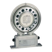
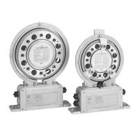
Torque Flange
Brand:
HBM
| Category:
Industrial Equipment
| Size: 1.29 MB
Table of Contents
Table of Contents
3
Safety Instructions
6
1 Torque Flange Versions
10
2 Application
11
3 Structure and Mode of Operation
12
4 Mechanical Installation
13
Conditions on Site
14
Installation Orientation
14
Installation Options
15
Installation Without Dismantling the Antenna Ring (Without Speed Measuring System)
15
Installation with Subsequent Stator Mounting (Without Speed Measuring System)
16
Installation Example with Couplings
17
Installation Example with Joint Shaft
17
Mounting the Rotor
18
Installing the Stator
20
Installing the Clamp Fixture
22
Mounting the Slotted Disc (Optical Speed Measuring System)
24
Fitting the Mounting Elements (Speed Measuring System)
25
Fixing the Mounting Elements
26
Mounting the Torque Flange with a Speed Measuring System
26
Aligning the Stator (Speed Measuring System)
28
Magnetic Speed Measuring System
28
Optical Speed Measuring System
32
5 Electrical Connection
34
General Information
34
Shielding Design
35
Option 2, Code KF1
36
Adaptation to the Cable Length
36
Option 2, Code SF1/SU2
38
Supply Voltage
40
6 Calibration
42
Calibration Option 2, Code KF1
42
Calibration Option 2, Code SF1/SU2
43
7 Settings
44
Torque Output Signal, Code KF1
45
Torque Output Signal, Code SF1/SU2
45
Setting up the Zero Point
46
Functional Testing
47
Power Transmission
47
Testing the Optical Speed Module
47
Setting the Pulse Count
49
Magnetic Speed Measuring System
49
Optical Speed Measuring System
51
Vibration Suppression (Hysteresis)
53
Form of Speed Output Signal
54
Type of Speed Output Signal
55
Optical Speed Measuring System with a Reference Pulse
55
8 Loading Capacity
57
Measuring Dynamic Torque
57
9 Maintenance
59
Torque Flange Maintenance
59
Speed Module Maintenance
59
Magnetic Speed Measuring System
59
Optical Speed Measuring System
59
10 Dimensions
60
Rotor Dimensions
60
Rotor Dimensions with the Magnetic Speed System
62
Stator Dimensions
63
Stator Dimensions with the Magnetic Speed System
64
Mounting Dimensions
65
11 Order Numbers, Accessories
66
12 Specifications
67
13 Supplementary Technical Information
75
Output Signals
75
Output MD Torque (Connector 1)
75
Output N: Speed and Speed with a Reference Pulse (Connector 2)
76
Connector 2, Double Frequency, Stat. Direction of Rotation Signal
77
Axial and Radial Run-Out Tolerances
78
HBM T10FS Mounting Instructions (76 pages)
Torque Flange
Brand:
HBM
| Category:
Industrial Equipment
| Size: 0.74 MB
Table of Contents
Table of Contents
3
Safety Instructions
6
1 Torque Flange Versions
10
2 Application
11
3 Structure and Mode of Operation
12
4 Mechanical Installation
13
Conditions on Site
14
Mounting Position
14
Installation Possibilities
15
Installation Without Undoing the Antenna Ring
15
(Without Speed Measuring System)
15
Installation with Subsequent Stator Mounting
16
(Without Speed Measuring System)
16
Installation Example with Couplings
17
Installation Example with Joint Shaft
17
Mounting the Rotor
18
Installing the Stator
20
Mounting of the Clamp Fixture
21
Installing the Slotted Disc (Speed Measuring System)
23
Fitting the Mounting Elements (Speed Measuring System)
24
Fixing the Mounting Elements
25
Installing the Torque Flange with the Speed
25
Measuring System
25
Aligning the Stator (Speed Measuring System)
27
Magnetic Speed Measuring System
27
Optical Speed Measuring System
31
5 Electrical Connection
33
General Instructions
33
Shielding Design
33
Option 2, Code KF1
34
Adaptation to the Cable Length
34
Option 2, Code SF1/SU2
36
Supply Voltage
39
6 Calibration
40
Calibration Option 2, Code KF1
40
Calibration Option 2, Code SF1/SU2
41
7 Settings
42
Torque Output Signal, Code KF1
43
Torque Output Signal, Code SF1/SU2
43
Setting up the Zero Point
44
Functional Testing
45
Power Transmission
45
Testing the Optical Speed Module
46
Setting the Pulse Count
47
Magnetic Speed Measuring System
47
Optical Speed Measuring System
50
Vibration Suppression (Hysteresis)
51
Form of the Rotation Speed Output Signal
52
Type of the Rotation Speed Output Signal
53
Optical Speed Measuring System with a Reference Pulse
53
8 Loading Capacity
55
Measuring Dynamic Torque
55
9 Maintenance
57
Torque Flange Maintenance
57
Speed Module Maintenance
57
Magnetic Speed Measuring System
57
Optical Speed Measuring System
57
10 Dimensions
58
Rotor Dimensions
58
Rotor Dimensions with the Magnetic Speed System
59
Stator Dimensions
60
Stator Dimensions with the Magnetic Speed System
61
Mounting Dimensions
62
11 Order Numbers, Accessories
63
12 Specifications
64
13 Supplementary Technical Information
71
Output Signals
71
Output MD Torque (Plug 1)
71
Output N: Speed and Speed with a
72
Reference Pulse (Plug 2)
72
Plug 2, Double Frequency, Stat. Direction of Rotation Signal
73
Circular Run out Values
74
Advertisement
Advertisement
Related Products
HBM T10FH
HBM T10F
HBM T10F KF1
HBM T10F SF1
HBM T10F SU2
HBM T10FM
HBM T10S2
HBM T10S3
HBM T10S4
HBM T10S5
HBM Categories
Transducer
Measuring Instruments
Accessories
Amplifier
Industrial Equipment
More HBM Manuals
Login
Sign In
OR
Sign in with Facebook
Sign in with Google
Upload manual
Upload from disk
Upload from URL