Sign In
Upload
Manuals
Brands
Harmonic Manuals
Media Converter
ProView 7000
Harmonic ProView 7000 Manuals
Manuals and User Guides for Harmonic ProView 7000. We have
5
Harmonic ProView 7000 manuals available for free PDF download: User Manual, Installation Manual, Quick Setup Manual
harmonic ProView 7000 User Manual (218 pages)
Multifunctional Receiver
Brand:
harmonic
| Category:
Receiver
| Size: 3.61 MB
Table of Contents
Table of Contents
6
Chapter 1 Introduction
11
General Information
11
Main Proview 7000™/7100 Applications
12
Proview 7000™ Platform Main Features and Configurations
12
TS Descrambling Applications
12
Multi-Transport Stream Descrambler
13
Multi-Format Decoder
14
DMS (Distribution Management System)
16
Proview 7000™ Mechanical Structure
17
Proview 7000™ Enclosure
17
Proview 7000™ Rear Panel
17
Proview 7000™/7100 Front Panel
17
Proview 7000™ Management
18
Chapter 2 Quick Start
19
Installation and Cable Connection
19
Electrical Connection
19
Installation
19
Cable Connections
20
Switching on
20
Configuring the IP Parameters
20
Configuring and Monitoring
21
A Typical Proview 7000™ Configuration Using the Front Panel
21
EMS Initial Setup
25
A Typical Proview 7000™ Configuration Using EMS
27
Chapter 3 Front Panel Overview
32
Main Elements and Structure
32
Front Panel Display
33
Menu
34
Parameter
34
Edit Value Pages
35
Radio Select Pages
35
Chapter 4 Device Configuring Using the Front Panel
36
Configuring the DVB-S/S2 Input Port Properties
36
Configuring the Decoding
39
Service Selection Mode
40
Video Configuration
41
PCR Configuration
43
Audio 1 / 2 Configuration
44
VBI/VANC Configuration
45
DPI to GPI
46
Routing and Descrambling
46
Configuring the Gbe Ports, Sockets and Routing Table
50
CA Definitions
53
Biss
53
CAM 1/2 Sub Menu
53
CAM Association
53
Selecting All Elementary Streams
53
Accessing the CAM MMI Menu
54
Configuring Only Relevant Elementary Streams
54
Unit Menu
54
Management Port Menu
54
HW Inventory Menu
55
SW Version Menu
55
BOOTP Menu
56
Date/Time Menu
56
GPI Menu
56
LCD Contrast Menu
56
License
56
Reset Unit Menu
56
Set Active Version
56
Restore to Defaults Menu
57
Presets
57
Chapter 5 Monitoring Using the Front Panel
58
Device Monitoring
58
Status OK
58
Alarms
59
Monitoring the DVB-S/S2 Input Port Properties
61
Monitoring the Decoding
62
Chapter 6 Remote Management Using EMS
63
Configuring the IP Parameters
63
EMS System Requirements
64
Installing EMS
64
Adding a Device
65
Launching EMS
65
Changing a Device's Connection Settings
66
Checking Device Connectivity
67
Connecting a Device
67
Disconnecting a Device
68
Displaying the Device Explorer
69
EMS GUI Structure
69
Removing a Device
69
Manipulating EMS GUI Components
70
Refreshing the EMS Screen
70
EMS Device Explorer
72
Chapter 7 Device Configuring Using EMS
74
Physical Input Ports and Slots
74
ASI Input Port Properties
75
DVB-S/S2 Input Port Properties
75
Gbe Ports for Input
80
CAM Slots
85
CAM Properties
87
BISS Table Management
88
Multiplex Inputs
89
Input Programs Management
90
Input Tables Management
91
Input Unreferenced Pids Management
92
Multiplex in Port Properties
92
Input Program Properties
95
Input Conditional Access Messages Properties
96
Input Elementary Stream Properties
96
Input Tables Properties
97
7.2.9 Input Unreferenced Pid Properties
98
Input Unreferenced PID Properties
98
Multiplex & Decoding Outputs
98
Multiplex Output
99
Multiplex Output
100
Multiplex Output Programs Management
101
7.3.4 Output Multiplex Program Properties
101
Multiplex Output
102
Pass through TS
104
Multiplex Output Properties
105
Click Properties on the EMS Toolbar
105
Explorer Tab
105
Transport Stream Port Route Properties Dialog
106
Output Multiplex Program Properties
107
Output Multiplex Elementary Stream Properties
108
Output Tables Properties
109
Output Unreferenced PID Properties
111
Decoding Channel Properties
112
Related Topics
112
Physical Outputs
123
ASI Output Port Properties
124
Gbe Ports for Output
125
Element Properties
128
Cross Connections
129
Setting Multiplex Cross Connections
129
Input to Decoder Channel Connection
137
CAM Slot Management
138
Editing and Deleting
138
Descrambling a Cross Connected Program
139
Descrambling a Decoded Program
140
EMS Connection Wizard
140
Setting Program Cross-Connection Using the Connection Wizard
141
Setting Decoding Channel Using the Connection Wizard
142
Low Delay Mode
143
Selecting Low Delay Mode
144
Device Management
145
Device Identification
146
Reset CAM Slot
146
Log-In / Log-Out Control of the Device
147
Managing Presets
147
Setting Up/Changing the Device Log-In Password
147
Backing Up/Restoring the Device Configuration
150
Restoring the Factory/Default Device Access Passwords
152
HDMI and DVI Output
146
Reboot Device
146
Device Properties
153
Network Properties
153
Hardware Properties
155
Device Communication Properties
160
Device Users' Access Properties
162
Device Software Upgrade Properties
163
Device License Properties
164
Device Date and Time Properties
165
GPI Properties
165
Chapter 8 Monitoring Using EMS
167
Device Communication Status
167
Alarms
168
Alarm Properties
169
Alarm History
169
Refreshing the EMS Screen
170
DVB-S/S2 Input Port Properties Status
171
Decoding Channel Properties Status
172
Decoding Channel Properties Monitoring
174
Chapter 9 Contacting Harmonic Support
176
Appendix A Characteristics and Specifications
177
A.1 DVB-S/S2 RF Input Interfaces
177
A.2 Transport Stream Input Interfaces
177
A.4 Transport Stream Processing
178
Conditional Access (DVB-CI)
178
A.3 Transport Stream Output Interfaces
178
Transport Stream Output Interfaces
178
A.6 Video and Audio Decoding
179
A.7 Video and Audio Interfaces
180
A.8 Control and Monitoring
180
A.10 Environment
181
A.11 Physical and Electrical Characteristics
181
Appendix B Connectors and Front End Card Options
182
A.9 Compliance
181
Emc
181
Safety
181
B.1 Overview of Rear Panel Ports and Connectors
182
B.2 RGB Port Pin Configuration
185
B.3 Proview 7000™ GPI Port Pin Configuration
186
B.4 Proview 7100™ GPI Port Pin Configuration
187
B.5 GPI Relay Position Names
188
B.6 Front End Card Features
189
Appendix C Device Explorer Icons
192
Appendix D Front Panel Menu Tree
194
Appendix E Proview 7000™ Alarm List
195
Appendix F Software Management
199
F.1 Active Version Management
199
F.2 Software Upgrade Manager
200
Upgrading the Firmware of Proview 7000S
201
Viewing the Software Upgrade Log
201
Glossary
202
Advertisement
Harmonic ProView 7000 User Manual (230 pages)
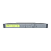
Integrated Reciever and Stream Processor
Brand:
Harmonic
| Category:
TV Tuner
| Size: 3.35 MB
Table of Contents
Table of Contents
6
Chapter 1 Introduction
11
General Information
11
Main Proview 7000 Applications
11
TS Descrambling Applications
11
Proview 7000 Platform Main Features and Configurations
12
Multi-Transport Stream Descrambler
13
Multi-Format Decoder
14
DMS (Distribution Management System)
16
Proview 7000 Mechanical Structure
16
Proview 7000 Enclosure
16
Proview 7000 Front Panel
16
Figure 1-1: Proview 7000 Platform General View
16
Proview 7000 Rear Panel
17
Proview 7000 Management
17
Chapter 2 Hardware Installation
18
Safety Precautions
18
Inventory Check
18
Power Supply to the Unit
19
Installing the Unit in a Rack
19
Fitting the Brackets
19
Installing the L Shape Slides
19
Mounting Proview 7000 Units in the 19" Rack
20
Insertion of the DVB-CI Module (PCMCIA)
21
Electrical Power Connection
21
Figure 2-1: Proview 7000 with the DVB-CI Module and Smart Card
21
Figure 2-2: AC Connector
21
Connecting the Cables
22
Switching on
23
Figure 2-3: Front Panel Startup Display
23
Chapter 3 Configuration and Monitoring
24
Configuring the IP Parameters
24
The Proview 7000 EMS
24
EMS System Requirements
24
Installing EMS
25
Launching the Proview 7000 EMS
26
Figure 3-1: EMS Window
27
How to Configure and Monitor the Proview 7000
28
Configuring the Proview 7000 Using the Front Panel
28
Monitoring the Proview 7000 Using the Front Panel
31
Configuring the Proview 7000 Using EMS
32
Monitoring the Proview 7000 Using EMS
38
Low Delay Mode
38
Selecting Low Delay Mode
38
Figure 3-2: Selecting Low Delay Mode
39
Proview 7000 (EMS) Structure
40
GUI Display TIPS
40
Figure 4-1: Proview 7000 EMS Graphical User Interface
41
Devices Box
42
Device Explorer Tabs
42
Alarms Tab
42
Figure 4-2: Alarm Tab
43
Alarm History Tab
44
EMS Status Bar
45
EMS Menu
45
EMS Toolbar
45
Figure 4-3: EMS Toolbar
45
Proview 7000 EMS Menu Bar
47
File Menu
47
Figure 4-4: EMS Menu Bar
47
Actions Menu
48
Administration Menu
48
Tools Menu
49
Window Menu
50
Help Menu
50
Proview 7000 Device Management
51
Accessing the Proview 7000 Device Management Functions
51
Figure 4-5: Device Tooltip
51
Figure 4-6: Device Context Menu
52
Device Communication Status
53
Device Management Functions
53
Figure 4-7: Add Device Dialog
54
Figure 4-8: Presets Management Dialog
58
Figure 4-9: Backup and Restore Configuration Dialog
61
Device Explorer
64
Figure 4-10: Device Explorer Tab
64
Physical Input Box
67
Figure 4-11: Physical Input Box Hierarchy
68
Multiplex Input Box
69
Multiplex & Decoding Output Box
72
Multiplex Output Programs Management
75
Multiplex Output
76
Pass through TS
78
Physical Output Box
79
Element Properties Configuration
80
Figure 4-12: Physical Output Box
80
Device Properties
81
Figure 4-13: Device Properties Dialog - Network Tab
82
Figure 4-14: Device Properties Dialog - Hardware - Platform Tab
84
Figure 4-15: Device Properties Dialog - Hardware - Main Board Tab
85
Figure 4-16: Device Properties Dialog - Hardware - Front End Tab
86
Figure 4-17: Device Properties Dialog - Hardware - Bottom Card Tab
87
Figure 4-18: Device Properties Dialog - Hardware - Top Card Tab
88
Figure 4-19: Device Properties Dialog - Communications Tab
89
Figure 4-20: Device Properties Dialog - Users Tab
90
Figure 4-21: Device Properties Dialog - S/W Upgrade Tab
91
Figure 4-22: Device Properties Dialog - License Tab
92
Figure 4-23: Device Properties Dialog - Date & Time Tab
93
Physical Input Ports and Slots
93
Figure 4-24: DVB-S/S2 Input Port Properties
94
Figure 4-25: Gbe Port Properties (Input Mode) Dialog - General Tab
99
Figure 4-26: Gbe Port Properties (Input Mode) Dialog - Advanced Tab
100
Figure 4-27: Socket Properties (Input Mode) Dialog - General Tab
101
Figure 4-28: Socket Properties (Input Mode) Dialog - Advanced Tab
102
Figure 4-29: CAM Slot Properties Dialog
103
Figure 4-30: CAM Card Properties Dialog
104
Figure 4-31: Sample CAM MMI Dialog
105
Input Multiplex Properties
105
Input Unreferenced PID
109
Figure 4-32: Multiplex out 1 Port - Properties Dialog
110
Multiplex & Decoding Output Properties
110
The Multiplex & Decoding Output Box of the Device Explorer Tab Presents a Hierarchical Tree
110
Figure 4-33: Transport Stream Port Route Properties Dialog
111
Figure 4-34: Add Other Program Dialog
112
Figure 4-35: Program Properties Dialog
112
Figure 4-36: Video Elementary Stream Properties Dialog
113
Figure 4-37: Decoding Channel Properties - Service Tab
118
Figure 4-38: Decoding Channel Properties - Video Tab
119
Figure 4-39: Decoding Channel Properties - PCR Tab
121
Figure 4-40: Decoding Channel Properties - Audio Tab
122
Figure 4-41: Decoding Channel Properties Dialog - VBI/VANC Tab
123
Figure 4-42: Decoding Channel Properties - OSD Tab
126
Figure 4-43: Decoding Channel Properties - Status Tab
127
Physical Output Interface Properties
127
Figure 4-44: Gbe Port Properties (Output Mode) Dialog- General Tab
129
Figure 4-45: Gbe Port Properties (Output Mode) Dialog - Advanced Tab
129
Figure 4-46: Gbe Socket Properties (Output Mode) Dialog- General Tab
130
Cross Connections
131
Figure 4-47: Gbe Socket Properties (Output Mode) Dialog- Advanced Tab
131
Figure 4-48: TS Cross Connect
132
Setting Multiplex Cross Connections
132
Figure 4-49: Dynamic Program Cross Connection
134
Figure 4-50: CAT EMM Cross Connect
134
Figure 4-51: Unreferenced PID Cross Connect
135
Figure 4-52: Set Decoder Channel
138
Input to Decoder Channel Connection
138
CAM Slot Management
139
Figure 4-53: CAM Slot Properties
140
EMS Connection Wizard
141
Figure 4-54: Connection Wizard Dialog
141
Refreshing the EMS Screen
143
Chapter 5 Front Panel Interface
144
Proview 7000 Front Panel Operation
144
Main Elements and Structure
144
Figure 5-1: Proview 7000 Front Panel
144
Front Panel Screen Types
145
Front Panel Root Menu
147
Figure 5-2: Proview 7000 Front Panel Menu Tree Structure
148
Reception Menu
149
Decoding Menu
156
Routing and Descrambling Menu
166
Gbe Menu
167
Alarms Table Menu
169
Presets Menu
170
CAM Menu
171
Unit Menu
172
Chapter 6 Contacting Harmonic Support
176
Appendix A Characteristics and Specifications
177
A.1 DVB-S/S2 RF Input Interfaces
177
A.2 Transport Stream Input Interfaces
177
A.3 Transport Stream Output Interfaces
178
A.4 Transport Stream Processing
178
Conditional Access (DVB-CI)
178
A.6 Video and Audio Decoding
179
A.7 Video and Audio Interfaces
180
A.8 Control and Monitoring
180
A.9 Compliance
181
Emc
181
Safety
181
A.10 Environment
181
A.11 Physical and Electrical Characteristics
181
Appendix B Ports and Connectors
182
B.1 Overview of Rear Panel Ports and Connectors
182
Figure B-1: Proview 7000 Decoder Rear Panel
182
B.2 RGB Port Pin Configuration
184
Figure B-2: D-Sub 15 Pinouts
184
Appendix C Front End Card Features
186
Appendix D Proview 7000 Alarm List
188
Appendix E Software Management
191
E.1 Active Version Management
191
E.2 Software Upgrade Manager
192
Upgrading the Firmware of Proview 7000S
193
Viewing the Software Upgrade Log
193
Glossary
194
Harmonic ProView 7000 Installation Manual (37 pages)
Brand:
Harmonic
| Category:
Receiver
| Size: 0.37 MB
Table of Contents
Table of Contents
5
Chapter 1: Proview™ 7000 Installation Guide
6
Inventory Check
6
Earthing
6
Power Supply to the Unit
7
Installing the Unit in a Rack
7
Fitting the Brackets
7
Installing the L Shape Slides
7
Mounting Proview 7000 Units in the 19" Rack
8
Electrical Power Connection
9
Connecting the Cables
9
Switching on
10
Appendix A: Contacting the Technical Assistance Center
11
Appendix B: Compliance, Safety, and Agency Approvals
13
Weee/Rohs Compliance Policy
13
Restricted Substance Statement
14
Names and Contents of Toxic and Hazardous Substances
14
Standards and Agency Approval
16
Canadian EMC Notice of Compliance
17
Important Safeguards and Notices
25
Safety and Regulatory Information for the Contentserver 3000 and Contentstore 3160
25
Lithium Battery Notice for Service Personnel
26
Safety Symbols
28
Safety Precautions
32
Consignes de Sécurité
32
AC Power Supply to the Unit
32
Alimentation Secteur de L'unité
33
DC Power Supply to the Unit
33
Alimentation C. C. de L'unité
33
Rack Mount Instructions
34
Instructions de Montage en Baie
34
Handling Fibre Channel Cables
34
Manipulation des Câbles Fibre Channel
34
Product End-Of-Life Disassembly Instructions
35
Product Disassembly Process
35
Safety Rules
35
Règles de Sécurité
36
Advertisement
Harmonic ProView 7000 Quick Setup Manual (15 pages)
Integrated Receiver and Stream Processor
Brand:
Harmonic
| Category:
Receiver
| Size: 0.52 MB
Harmonic ProView 7000 Installation Manual (6 pages)
Brand:
Harmonic
| Category:
Media Converter
| Size: 0.2 MB
Table of Contents
Safety Precautions
2
Inventory Check
2
Electrical Power Connection
5
Connecting the Cables
6
Advertisement
Related Products
Harmonic ProView 2900
Harmonic ProView 8100
Harmonic ProView 8100 RELEASE 1.3.1
Harmonic ProView PVR 6000 Series
harmonic ProView 7100
Harmonic 7017E
Harmonic 7014E
Harmonic 7019IL-GF
Harmonic 7014I-GF
Harmonic 7020I-GF
Harmonic Categories
Server
Media Converter
Storage
Computer Hardware
Receiver
More Harmonic Manuals
Login
Sign In
OR
Sign in with Facebook
Sign in with Google
Upload manual
Upload from disk
Upload from URL