Harmonic ProView 7000 User Manual
Integrated reciever and stream processor
Hide thumbs
Also See for ProView 7000:
- User manual (218 pages) ,
- Installation manual (37 pages) ,
- Quick setup manual (15 pages)

Related Manuals for Harmonic ProView 7000


Summary of Contents for Harmonic ProView 7000
- Page 1 ProView 7000™ Integrated Receiver and Stream Processor User Manual VERSION 2.4 Rev. A Manual Part No. MAN-PVR-7K-2.4...
- Page 2 Harmonic assumes no responsibility or liability arising from the use of the products described herein, except as expressly agreed to in writing by Harmonic. The use and purchase of this product do not convey a license under any patent rights, copyrights, trademark rights, or any intellectual property rights of Harmonic.
- Page 3 用手册的规定,对该产品进行使用或存储。 The Environmental Protective Use Period for Harmonic products is 20 years unless displayed otherwise on the product. The EPUP period is valid only when the products are operated or stored as per the conditions specified in the product manual.
- Page 4 Agency Approval EMI/EMC: EN55022, Class A, EN55024 Safety: EN 60950-1, EN60825-1 TUV-GS or T-Mark, CE Japan Standards Agency Approval EMI: VCCI V-3 2009 VCCI Australia and New Zealand Standards Agency Approval EMI: AS/NZS CISPR22:2006 © 2011 Harmonic Inc. All rights reserved.
- Page 5 CAUTION: The Caution symbol calls your attention to information that, if ignored, can adversely affect the performance of your Harmonic product, or that can make a procedure needlessly difficult. LASER DANGER: The Laser symbol and the Danger alert call your attention to information about the lasers in this product that, if ignored, can cause physical harm to you.
-
Page 6: Table Of Contents
ProView 7000 Mechanical Structure ........ - Page 7 ProView 7000 Front Panel Operation........144...
- Page 8 RGB Port Pin Configuration ......... . 184 Appendix C Front End Card Features Appendix D ProView 7000 Alarm List Appendix E Software Management Active Version Management .
- Page 9 ProView 7000 Platform General View ........
- Page 10 ProView 7000 Decoder Rear Panel........
-
Page 11: Chapter 1 Introduction
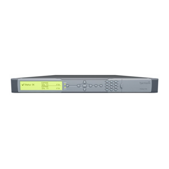
■ General Information The Harmonic ProView 7000 is a single rack unit (1RU) scalable receiver, DVB descrambler, multi-format video decoder and MPEG stream processor. The modular ProView 7000 addresses the full spectrum of content reception applications from single channel decoding to descrambling and re-multiplexing of multiple transport streams. -
Page 12: Proview 7000 Platform Main Features And Configurations
ASI and GbE outputs ■ Re-multiplexing capabilities with up to four multiplexes ■ The ProView 7000 can generate up to four (4) TS outputs from one (1) TS input ■ Re-generation of DVB and MPEG PSI/SI ■ Low Delay decoding mode ■... -
Page 13: Multi-Transport Stream Descrambler
ProView 7000 Platform Main Features and Configurations 1.3.1 Multi-Transport Stream Descrambler The ProView 7000 Multi-Transport Stream Descrambler is an ideal and cost effective receiver solution for digital headend turn around applications. The platform’s DVB-S/S2 , ASI and IP inputs, along with powerful descrambling and multiplexing capabilities, fully addresses the headend reception application requirements. -
Page 14: Multi-Format Decoder
1.3.2 Multi-Format Decoder The ProView 7000 can be configured as a multi-format video decoder. The ProView 7000 is for both Standard Definition (SD) and High Definition (HD) resolutions for MPEG-2 and MPEG-4 AVC decoding as well as MPEG-2 4:2:0 in SD (PAL/NTSC). - Page 15 Chapter 1 Introduction ProView 7000 Platform Main Features and Configurations Video decoding formats: MPEG-2 SD 4:2:0 MP@ML ■ MPEG-2 HD 4:2:0 MP@HL ■ MPEG-4 AVC SD MP@L3 ■ MPEG-4 AVC HD MP@L4.0 / HP@4.0 ■ Maximum video rate: MPEG-2 SD – 15 Mbps ■...
-
Page 16: Dms (Distribution Management System)
1.4.1 ProView 7000 Enclosure The ProView 7000 platform is housed in a 19" 1RU mount ready enclosure. See Figure 1–1. It includes fans for right to left air passage for side-to-side heat dissipation, the ProView 7000 may be installed in a rack without spacing between units. This allows increased flexibility for installation of a large number of units in limited space environments and integration with additional DVB equipment. -
Page 17: Proview 7000 Rear Panel
1.4.3 ProView 7000 Rear Panel The rear panel of the ProView 7000 platform includes all of the required professional input and output connectors. The AC connector and power switch are also located on the rear panel as well as the GND lug for grounding the unit when installed in a rack. The rear panel is provided in various configurations as required for different applications. -
Page 18: Chapter 2 Hardware Installation
Do not move or ship equipment unless it is correctly packaged in its original wrapping and ■ shipping containers. Only Harmonic trained personnel can perform service and maintenance. ■ To prevent lightning damage, ground the unit according to local regulations. -
Page 19: Power Supply To The Unit
■ DANGER: To avoid electrocution, ensure that the rack has been correctly grounded before switching on the ProView 7000 device. When removing the unit, remove the grounded connection only after the unit is switched off and unplugged. Installing the Unit in a Rack CAUTION: For rack installation, ensure that a designated 19"... -
Page 20: Mounting Proview 7000 Units In The 19" Rack
Address Harmonic support for calculating the maximum load on the rack. To mount the 19"/42U rack with the ProView 7000 units: 1. Mount ProView 7000 units in groups of no more than five units on each pair of brackets. 2. Leave one-unit-space between each group of five units. -
Page 21: Insertion Of The Dvb-Ci Module (Pcmcia)
Smart Card, inserted with the UP arrow pointing upwards and forwards. CAUTION: Do not remove or insert the DVB-CI module or the Smart Card while the ProView 7000 is powering up or initializing. Figure 2–1: ProView 7000 with the DVB-CI module and Smart Card... -
Page 22: Connecting The Cables
240 V Wechselstrom, 20 A (bzw. in den USA 120 V Wechselstrom, 20 A) an den Phasenleitern (allen stromführenden Leitern) verwendet wird. Connecting the Cables All ProView 7000 connectors are located on the rear panel, see Figure B–1 on page 182. -
Page 23: Switching On
Switching On Switching On Before switching the ProView 7000 on, make sure that all cables are correctly connected. Ensure that the unit is connected to the main power supply and correctly grounded. ❖ Switch the unit on with the rear power switch. -
Page 24: Chapter 3 Configuration And Monitoring
Drop Changes The ProView 7000 EMS The ProView 7000 EMS application provides a GUI for easy management the ProView 7000s. You can manage up to 10 devices with EMS. Most EMS functions can be performed via the front panel. You need to have an internet or LAN connection to use EMS. -
Page 25: Installing Ems
The ProView 7000 EMS 3.2.2 Installing EMS The ProView 7000 EMS is stored in the ProView 7000 for easy installation using a web browser. To install the ProView 7000 EMS: 1. Run a web browser and enter the ProView 7000 IP address. -
Page 26: Launching The Proview 7000 Ems
2. Click on the EMS toolbar. Add Device 3. The EMS displays the ProView 7000 Device – Add dialog. 4. Enter a name for the new ProView 7000 device. 5. Enter the IP Address of the new ProView 7000 device. -
Page 27: Figure 3-1: Ems Window
Multiplex and Physical Output port box decoding Output box EMS Menu EMS Toolbar Box expand/collapse control Device box Device stream tab Alarm report tab Alarm history tab Figure 3–1: EMS Window © 2011 Harmonic Inc. ProView 7000 v.2.4, Rev. A... -
Page 28: How To Configure And Monitor The Proview 7000
How to Configure and Monitor the ProView 7000 How to Configure and Monitor the ProView 7000 You can configure and monitor the ProView 7000 with either the front panel or over an IP network using the ProView 7000 EMS. Configuring the ProView 7000 using the Front Panel ■... - Page 29 Chapter 3 Configuration and Monitoring How to Configure and Monitor the ProView 7000 Select Apply Changes Navigate Root > GbE > GbE Port (1 or 2) > Admin Status Set the Admin Status to Up. Navigate Root > GbE > Socket Configuration > Socket In > Socket (no.) >...
- Page 30 Chapter 3 Configuration and Monitoring How to Configure and Monitor the ProView 7000 NOTE: In this mode, stream information is not processed and output bit rate is identical to input bit rate. Navigate Root > Routing and Descrambling > TS (no.) > Activation...
-
Page 31: Monitoring The Proview 7000 Using The Front Panel
15. Select the CAM slot. 3.3.2 Monitoring the ProView 7000 using the Front Panel How to monitor the correct operation of the ProView 7000 device. Status OK When there are no errors the message displays on the LCD and the two STATUS OK ProView 7000 front panel LEDs are lit green. -
Page 32: Configuring The Proview 7000 Using Ems
3.3.3 Configuring the ProView 7000 using EMS The ProView 7000 has four logical multiplexes. A license is required for using more than one multiplex. Some hardware configurations support up to four satellite RF inputs. All ProView 7000s have 2 GbE data ports. - Page 33 CAM slot element. It enables you to associate a CAM slot to a multiplex in port and enable descrambling mode. 4. Descrambling a Program – The ProView 7000 EMS enables you to select individual programs to descramble. 5. Input Port association – The DVB-S/S2 In ports in the Physical Input box are associated by default to multiplex ins in the Multiplex Input box according to their index numbers (1–4),...
- Page 34 Chapter 3 Configuration and Monitoring How to Configure and Monitor the ProView 7000 Click in the bottom left corner of the properties dialog. Show Status The displayed properties are divided into two sections; the section on the left displays editable properties and the section on the right provides informative/status properties that cannot be edited by the EMS user.
- Page 35 Chapter 3 Configuration and Monitoring How to Configure and Monitor the ProView 7000 If the GbE mode is configured as In in the Set GbE Mode dialog, configure it to Out and click The device reboots. Expand the device tree in the Physical Output box to reveal the GbE ports.
- Page 36 Chapter 3 Configuration and Monitoring How to Configure and Monitor the ProView 7000 6. To associate a different port or additional ports to a Multiplex In: Drag a Port from the Physical Input box to a Multiplex In in the Multiplex Input box.
- Page 37 Chapter 3 Configuration and Monitoring How to Configure and Monitor the ProView 7000 8. To decode a program: Drag the program name from the Multiplex Input box and drop it on the decoding channel in the Multiplex & Decoding Output box.
-
Page 38: Monitoring The Proview 7000 Using Ems
Low Delay Mode The ProView 7000 Low Delay Mode is designed to work with an Ellipse 1000/2000 encoder in Low Delay mode. The end-to-end delay should be less than 9 frames for PAL and 10 frames for NTSC. Low Delay Mode automatically detects regular video streams that do not require Low Delay Mode and treats them accordingly. -
Page 39: Figure 3-2: Selecting Low Delay Mode
Chapter 3 Configuration and Monitoring Low Delay Mode 4. Select for Buffer Management in the Advanced box, see Figure 3–2. Low Delay Low Delay option Figure 3–2: Selecting Low Delay Mode 5. Click Apply © 2011 Harmonic Inc. ProView 7000 v.2.4, Rev. A... -
Page 40: Proview 7000 (Ems) Structure
4.1.1 GUI Display TIPS The ProView 7000 EMS GUI displays the graphical information in boxes. These boxes can be collapsed when not needed or expanded to fill all available screen space. A right/left or up/down set of arrows (Box Expand/Collapse Control, see EMS GUI example) ■... -
Page 41: Figure 4-1: Proview 7000 Ems Graphical User Interface
Output box EMS Menu EMS Toolbar Box expand/ collapse control Device box Device stream tab Alarm report tab Alarm history tab Status bar Figure 4–1: ProView 7000 EMS Graphical User Interface © 2011 Harmonic Inc. ProView 7000 v.2.4, Rev. A... -
Page 42: Devices Box
NOTE: The ProView 7000 EMS can manage several devices and can display the Device Explorer tabs of any of them, according to the user needs. Each displayed device stream tab is labeled at the bottom of the tab with the device name (as displayed in the Devices box). -
Page 43: Figure 4-2: Alarm Tab
Chapter 4 Element Management System (EMS) ProView 7000 EMS Structure The Alarms tab displays all the alarms received by the EMS from the ProView 7000 devices. Figure 4–2: Alarm tab To refresh the alarm list on demand: 1. Right-click any alarm in the list. -
Page 44: Alarm History Tab
4.1.5 Alarm History Tab The Alarm History tab keeps a record of alarms triggered by the ProView 7000 devices managed by the EMS. You can export the alarm history in CSV format. The alarm severity color codes are the same as those in the Alarm tab. -
Page 45: Ems Status Bar
Menu. 4.1.8 EMS Toolbar The EMS toolbar has buttons for direct access to the ProView 7000 EMS most used control and managing functions. Figure 4–3: EMS toolbar Use the EMS toolbar items to activate one of the following managing tools for the active device (selected in the Device box): Add Device –... - Page 46 ■ ProView 7000 EMS. For details, refer to 4.3.3.11 Disconnecting a Device. Connection Wizard – Opens the ProView 7000 Connection Wizard. For details, refer to ■ 4.6.4 EMS Connection Wizard. Upgrade – Opens the Software Upgrade Manager dialog to perform software upgrades ■...
-
Page 47: Proview 7000 Ems Menu Bar
Chapter 4 Element Management System (EMS) ProView 7000 EMS Menu Bar ProView 7000 EMS Menu Bar The EMS Menu provides access to ProView 7000 EMS control and managing functions in a menu format. Figure 4–4: EMS menu bar The information provided by the EMS Menu is divided into the following main menu... -
Page 48: Actions Menu
The Administration menu consists of the following items: Table 4–3: Administration Menu Items Command Description Launches the EMS Add ProView 7000 dialog. This dialog allows adding a Add ProView 7000… new device-for managing by the EMS. For details, refer to 4.3.3.1 Adding a New ProView 7000 Device. -
Page 49: Tools Menu
NOTE: Active only when a CAM Slot is selected. Use this menu to manage several configurations, see 4.3.3.7 Manage Manage Presets… Presets. Displays the ProView 7000 Back Up / Restore Configuration dialog. For Back Up / Restore details, refer to 4.3.3.8 Backing Up/Restoring the Device Configuration. -
Page 50: Window Menu
Description Launches the help window, allowing the user to query for help issues Help Contents within the help contents. About ProView 7000 EMS… Displays information about the ProView 7000 EMS version. © 2011 Harmonic Inc. ProView 7000 v.2.4, Rev. A... -
Page 51: Proview 7000 Device Management
ProView 7000 Device Management ProView 7000 Device Management In order to manage a ProView 7000 device using the ProView 7000 EMS, the user must first initiate a connection between the required device and the EMS interface. The connected devices are listed and displayed in the Devices box of the ProView 7000 EMS. Hover the mouse pointer over a device icon to display the display tip. -
Page 52: Figure 4-6: Device Context Menu
A dynamic command, changing according to the selected device’s Connect/ Disconnect connection status. Allows connecting or disconnecting the device to the ProView 7000 EMS. For details, refer to 4.3.3.2 Connecting a Device 4.3.3.11 Disconnecting a Device, respectively. A dynamic command, changing according to the selected device's log... -
Page 53: Device Communication Status
4.3.2 Device Communication Status The communication state of the ProView 7000 EMS with a ProView 7000 device is shown by the graphical display of the device icon in the Devices box. The alarm severity level is indicated by the device icon LEDs. A list follows with the descriptions: A device that is disconnected or not logged into is displayed in light gray. -
Page 54: Figure 4-7: Add Device Dialog
This parameter is set to 2 tries by defaults. 10. Click to drop changes, or to save advanced parameters. Cancel The Advanced dialog closes and the EMS returns to the Add ProView 7000 Device dialog. © 2011 Harmonic Inc. ProView 7000 v.2.4, Rev. A... - Page 55 1. Right-click the icon of the connected ProView 7000 device in the Device box. A device context menu displays. NOTE: A disconnected ProView 7000 device is not communicating with the ProView 7000 EMS and is marked in the device list by a grayed device icon.
- Page 56 4.3.3.5 Displaying the Device Explorer Tab Displaying the Device Explorer tab for an EMS managed ProView 7000 device displays the collapsible information trees in the four stream information boxes (physical input tree, input multiplexing tree, output multiplexing and decoding tree and physical output tree) and populates them with the respective tree top-level interface information (refer to 4.4 Device...
- Page 57 NOTE: Displaying the Device Explorer tab for a connected ProView 7000 device in the Devices box can also be done in any one of the following ways: Drag the active ProView 7000 icon from the Device box to any box to the right of the Device box. ■...
-
Page 58: Figure 4-8: Presets Management Dialog
Activating a Preset ■ Rename — see Renaming a Preset ■ Delete — see Deleting a Preset ■ Download — see Downloading Presets ■ Upload — see Uploading a Preset ■ © 2011 Harmonic Inc. ProView 7000 v.2.4, Rev. A... - Page 59 4. Enter a name for the preset. 5. Click Activating a Preset Use the Activate button to activate a preset in the ProView 7000. The device reboots when you activate a preset. To activate a preset: 1. Select the device in the Devices box.
- Page 60 5. Select a destination folder for the preset files. 6. Click Uploading a Preset Use the Upload button to upload a preset to a ProView 7000. Preset files which you upload must have different names to those already in the ProView 7000. To upload a preset: 1.
-
Page 61: Figure 4-9: Backup And Restore Configuration Dialog
3. Browse the path and select the saved configuration name in the Restore Device section of the dialog. 4. Click Restore After confirming the retrieval, the EMS retrieves the configuration file and the ProView 7000 is reconfigured according to the saved set-up. © 2011 Harmonic Inc. ProView 7000 v.2.4, Rev. A... - Page 62 4. Enter the access code supplied by Harmonic and click Restore NOTE: The Harmonic supplied access code is valid for the same day only. Once the access passwords are reset to factory values, it is recommended to change and personalize them to protect the security of the device.
- Page 63 4.3.3.11 Disconnecting a Device A connected ProView 7000 device is communicating with the ProView 7000 EMS and is marked in the device list by a fully colored device icon. The icon is displayed in the Device box, and, if activated, it is also displayed in the Physical Input and Physical Output boxes.
-
Page 64: Device Explorer
ProView 7000 Device for details. Removing a device from the EMS management can be performed on any ProView 7000 device (i.e., listed in the Device box), regardless of its status; connected (full color icon), disconnected (gray icon) or even a not responding device (red marked icon). - Page 65 Drag the device icon from the Device Tree in the Devices box to the box on the right. ■ Once a Device Explorer tab is displayed, it displays until it is closed by the EMS user. The ProView 7000 EMS supports opening up to 10 Device Explorer tabs.
- Page 66 Chapter 4 Element Management System (EMS) Device Explorer The ProView 7000 EMS GUI uses a wide range of icons to identify elements displayed on the Device Explorer tab. The following table describes these icons. Table 4–8: Device Explorer Icons Icon Description...
-
Page 67: Physical Input Box
Physical Input Box The Physical Input box of the Device Explorer tab presents a hierarchical tree-structure of the ProView 7000 physical input ports for monitoring and configuring the features of each element displayed in the tree. Double-click the device icon then the branches to display the input physical tree structure. -
Page 68: Figure 4-11: Physical Input Box Hierarchy
4.7 Refreshing the EMS Refresh Device [device name] Screen. Displays the properties dialog for the marked element. For details, see Properties 4.5.2 Physical Input Ports and Slots. GbE in requires a license. © 2011 Harmonic Inc. ProView 7000 v.2.4, Rev. A... -
Page 69: Multiplex Input Box
NOTE: The Multiplex Input tree displays the transport rate level (in Mbps), summed at the tree highest level. The ProView 7000 supports up to four multiplex inputs. Right-click the Multiplex Input icon to display a context menu which features the following options: Table 4–10: Multiplex Input Icon Context Menu... - Page 70 NOTE: The properties of the input programs and the elementary streams related to each program in the multiplex input stream are detailed in 4.5.3.2 Input Program Properties, 4.5.3.3 Input Elementary Stream Properties 4.4.3.4 Multiplex Output Unreferenced PIDs Management. © 2011 Harmonic Inc. ProView 7000 v.2.4, Rev. A...
- Page 71 NOTE: The displayed tables are managed by the stream type defined (MPEG or DVB). The property of the various input tables in the multiplexed input stream is detailed in 4.5.3.5 Input Tables Properties. © 2011 Harmonic Inc. ProView 7000 v.2.4, Rev. A...
-
Page 72: Multiplex & Decoding Output Box
Multiplex & Decoding Output Box The Multiplex & Decoding Output box of the Device Explorer tab presents a hierarchical tree- structure of the decoded and multiplex outputs of the ProView 7000, comprises two branch types; multiplexing branches ( ) and the decoding branch ( The multiplexing branch provides monitoring and configuring options for the features of stream and each element in the branch;... - Page 73 Updates the EMS screen. For details, see 4.7 Refreshing the EMS Refresh Screen. Displays the marked element properties dialog. For details, see Properties 4.5.4 Multiplex & Decoding Output Properties. © 2011 Harmonic Inc. ProView 7000 v.2.4, Rev. A...
- Page 74 TIP: Multiplexing a Program or a PID can be also done by dragging the program icon or the PID icon from the multiplex input tree and dropping it in the multiplex output tree. For detailed instructions 4.6.1 Setting Multiplex Cross Connections. © 2011 Harmonic Inc. ProView 7000 v.2.4, Rev. A...
-
Page 75: Multiplex Output Programs Management
NOTE: The properties of the output programs and the elementary streams related to each program in the multiplex output stream are detailed in 4.5.4.3 Output Multiplex Program Properties 4.5.4.4 Output Multiplex Elementary Stream Properties. © 2011 Harmonic Inc. ProView 7000 v.2.4, Rev. A... -
Page 76: Multiplex Output
NOTE: The displayed tables are managed by the defined stream type (MPEG or DVB). The property of the various output tables in the multiplex output stream is detailed in 4.5.4.5 Output Tables Properties. © 2011 Harmonic Inc. ProView 7000 v.2.4, Rev. A... - Page 77 4.4.3.5 Decoding Channel Management Click the Decoding Channel branch in the Multiplex & Decoding Output box to display all the information related to the input program routed to the decoding channel. © 2011 Harmonic Inc. ProView 7000 v.2.4, Rev. A...
-
Page 78: Pass Through Ts
Right-click the TS Port Output Port icon or any of the elements in the branch, to display a drop-down menu which features the following items: © 2011 Harmonic Inc. ProView 7000 v.2.4, Rev. A... -
Page 79: Physical Output Box
■ GbE ports and sockets ■ When the Decoder module is installed in the ProView 7000 device the module provides a wide range of physical video and audio interfaces. All interfaces are displayed under the Decoder card branch. Right-click the device icon or any of the sub-elements in the Physical Output box to display a context menu which includes the following items: Table 4–14: Device Icon Context Menu... -
Page 80: Element Properties Configuration
Element Properties Configuration The Element Properties Configuration function, provided by the ProView 7000 EMS, allows monitoring and setting ProView 7000 properties at device level and down to specific operational elements in the device. This element can be a device selected in the Device box (details in 4.5.1 Device... -
Page 81: Device Properties
Chapter 4 Element Management System (EMS) Element Properties Configuration 4.5.1 Device Properties The Device properties allows monitoring and setting ProView 7000 system level parameters. To display the Device properties: 1. Select a device icon in the Devices box. 2. Click on the EMS toolbar. -
Page 82: Figure 4-13: Device Properties Dialog - Network Tab
Use the Routing Table Management dialog to manage up to five routing destinations for GbE mode In when the sender is on a different network. To display the Routing Table Management dialog: ❖ Click on the Network tab of the device properties dialog. Advanced © 2011 Harmonic Inc. ProView 7000 v.2.4, Rev. A... - Page 83 The Hardware properties tab provides the EMS user the ability to monitor the following parameters related to the ProView 7000 unit, arranged in the following groups / sub-tabs: NOTE: Each Hardware Properties sub-tab also displays the highest active alarm level related to the ProView 7000 device.
-
Page 84: Figure 4-14: Device Properties Dialog - Hardware - Platform Tab
■ Hardware Revision ■ Figure 4–14: Device properties dialog – Hardware – Platform tab Main Board The Main Board Properties tab displays the following ProView 7000 main board parameters: Main Board Serial number ■ Software version number ■ Main Board part number ■... -
Page 85: Figure 4-15: Device Properties Dialog - Hardware - Main Board Tab
Front End sensor temperature (in °C) ■ Front End FPGA version number ■ DVB-S and DVB-S2 (if available) demodulator version information ■ Requires a license with some hardware configurations, see Appendix C for details. © 2011 Harmonic Inc. ProView 7000 v.2.4, Rev. A... -
Page 86: Figure 4-16: Device Properties Dialog - Hardware - Front End Tab
The Bottom Card properties tab displays the following parameters on the bottom card installed in the device: Bottom card type ■ Bottom card part number ■ Bottom card serial number ■ Hardware Revision information ■ Decoder Software Version information ■ © 2011 Harmonic Inc. ProView 7000 v.2.4, Rev. A... -
Page 87: Figure 4-17: Device Properties Dialog - Hardware - Bottom Card Tab
The Top Card Properties tab displays the following parameters on the top card installed in the device: Top card type ■ Top card part number ■ Top card serial number ■ Hardware Revision information ■ © 2011 Harmonic Inc. ProView 7000 v.2.4, Rev. A... -
Page 88: Figure 4-18: Device Properties Dialog - Hardware - Top Card Tab
Device Communication Properties The Communications properties tab provides the EMS user the ability to manage the following parameters related to the ProView 7000 unit communication: Traps Destination Parameters Box Traps are SNMP notifications sent by the unit to a predefined address, without user intervention. -
Page 89: Figure 4-19: Device Properties Dialog - Communications Tab
UDP Port – Sets the UDP port number of the trap destination ❑ Description – Optional parameter, describing the trap destination ❑ Trap Community – Set the trap community ❑ 5. Click 6. Click Apply © 2011 Harmonic Inc. ProView 7000 v.2.4, Rev. A... -
Page 90: Figure 4-20: Device Properties Dialog - Users Tab
4.5.1.4 Device Users Access Properties You can log in to ProView 7000 devices using EMS on two levels; Configure and Monitor. The Configure defined user can monitor and configure the ProView 7000 devices and have access to all set-up functions provided by the EMS. -
Page 91: Figure 4-21: Device Properties Dialog - S/W Upgrade Tab
4.5.1.5 Device Software Upgrade Properties The ProView 7000 device software can be upgraded using non EMS managed tools, consisting of BOOTP and TFTP industry standard tools. The S/W Upgrade tab sets the number of retries for each one of these two upgrade tools. -
Page 92: Figure 4-22: Device Properties Dialog - License Tab
Chapter 4 Element Management System (EMS) Element Properties Configuration 4.5.1.6 Device License Properties The Device License tab displays the ProView 7000 licensed features. Figure 4–22: Device Properties dialog – License tab To enter a new license code: 1. Mark the Update license checkbox. -
Page 93: Physical Input Ports And Slots
Device Date and Time Properties The Date & Time tab enables the EMS operator to view and configure the current date and time, including time zone, of the ProView 7000 device. Figure 4–23: Device Properties dialog – Date & Time tab 4.5.2... -
Page 94: Figure 4-24: Dvb-S/S2 Input Port Properties
To display the DVB-S/S2 Input Port properties: 1. Select the DVB-S/S2 Input Port icon in the Physical Input box. 2. Click on the EMS toolbar. Properties Figure 4–24: DVB-S/S2 Input Port Properties © 2011 Harmonic Inc. ProView 7000 v.2.4, Rev. A... - Page 95 – Variable Coding Modulation format / Automatic • QPSK 1/4 • QPSK 1/3 • QPSK 2/5 • QPSK 1/2 • QPSK 3/5 Only available with certain hardware configurations, see Appendix C on page 185. © 2011 Harmonic Inc. ProView 7000 v.2.4, Rev. A...
- Page 96 ❑ A license is required for 16APSK modulation. Only available with certain hardware configurations, see Appendix C page 185. Only available with certain hardware configurations, see Appendix C on page 185. © 2011 Harmonic Inc. ProView 7000 v.2.4, Rev. A...
- Page 97 For Universal and Universal Wide satellite frequencies, the LNB Local Oscillator Frequency is set according to the 22 kHz Tone setting. Only available with certain hardware configurations, see Appendix C on page 185. © 2011 Harmonic Inc. ProView 7000 v.2.4, Rev. A...
- Page 98 The status properties displayed in the Status (right) section of the DVB-S/S2 In Port dialog consists of the following parameters: Carrier and Demodulator lock status – ProView 7000 attempts to lock onto a carrier even ■ when the port is not connected Carrier to noise ratio (C/N) measured value (in dBc) ■...
-
Page 99: Figure 4-25: Gbe Port Properties (Input Mode) Dialog - General Tab
Duplex Mode – You cannot change the Duplex Mode. It is fixed at Full Duplex. ■ Speed – You can configure the PHY speed when Autonegotiation is disabled. The default is ■ 1000. © 2011 Harmonic Inc. ProView 7000 v.2.4, Rev. A... -
Page 100: Figure 4-26: Gbe Port Properties (Input Mode) Dialog - Advanced Tab
Port for several sockets if you define the Source Specific Multicast and the Source IP Addresses are different. When the IP Address Type is Unicast, the ProView 7000 uses the active port IP address. When the IP Address Type is Multicast, you must enter the multicast IP address. -
Page 101: Figure 4-27: Socket Properties (Input Mode) Dialog - General Tab
De-Jitter Mode – All input sockets are de-jittered. The options are: ■ Low Delay Mode ❑ Normal Network Jitter (Less than 50 ms) ❑ High Network Jitter (Up to 300 ms) ❑ © 2011 Harmonic Inc. ProView 7000 v.2.4, Rev. A... -
Page 102: Figure 4-28: Socket Properties (Input Mode) Dialog - Advanced Tab
Chapter 4 Element Management System (EMS) Element Properties Configuration Figure 4–28: Socket Properties (Input mode) dialog - Advanced tab © 2011 Harmonic Inc. ProView 7000 v.2.4, Rev. A... -
Page 103: Figure 4-29: Cam Slot Properties Dialog
❑ CAM Vendor Card – Provides the following information for the CAM card in the slot: ■ Vendor name ❑ Number of descrambled programs ❑ Number of descrambled elementary streams ❑ © 2011 Harmonic Inc. ProView 7000 v.2.4, Rev. A... -
Page 104: Figure 4-30: Cam Card Properties Dialog
Element Properties Configuration Descrambled Programs – Displays the program PIDs descrambled by the CAM. ■ CAM Automatic Recovery Policy – You can configure the ProView 7000 to reset the CAM ■ when one of the following alarms is raised: CAM Descrambling Failure – Enabled by default. -
Page 105: Input Multiplex Properties
4.5.3 Input Multiplex Properties The Input Stream Multiplexing box of the Device Explorer tab presents a hierarchical tree- structure of the multiplex inputs of the ProView 7000. The Multiplex Input main branch properties dialog is detailed in 4.5.3.1 Multiplex Input Properties. - Page 106 To display the Input Program properties dialog: 1. Select the required Input Program icon in the Multiplex Input box on the Device Explorer tab. 2. Click on the EMS toolbar. Properties © 2011 Harmonic Inc. ProView 7000 v.2.4, Rev. A...
- Page 107 The program identification number (PID) of the input elementry stream type. ■ The ES type code (in hex) and description. ■ The language code for the ES (Not applicable for Video ES). ■ © 2011 Harmonic Inc. ProView 7000 v.2.4, Rev. A...
- Page 108 To display the Input Tables properties dialog: 1. Select the required Input Table icon from the Multiplex Input box on the Device Explorer tab. 2. Click on the EMS toolbar. Properties © 2011 Harmonic Inc. ProView 7000 v.2.4, Rev. A...
-
Page 109: Input Unreferenced Pid
The information provided by the Input Unreferenced PID Properties dialog includes the following: The packet identification number (PID) of the related input stream. ■ The type of the PID (Unreferenced). ■ © 2011 Harmonic Inc. ProView 7000 v.2.4, Rev. A... -
Page 110: Multiplex & Decoding Output Properties
Multiplex & Decoding Output Properties The Multiplex & Decoding Output box of the Device Explorer tab presents a hierarchical tree- structure of the multiplex and decoded outputs of the ProView 7000. The Multiplex & Decoding Output tree features two main branches: The Output Multiplexing main branch, detailed in 4.5.4.1 Multiplex Output... -
Page 111: Figure 4-33: Transport Stream Port Route Properties Dialog
Input Port – Displays the multiplex input port name. ■ Transport Stream ID – Displays the transport stream ID number. ■ Output Port – Displays the stream output port name. ■ © 2011 Harmonic Inc. ProView 7000 v.2.4, Rev. A... -
Page 112: Figure 4-34: Add Other Program Dialog
Properties Figure 4–35: Program Properties dialog The Program Properties dialog contains the following items: Enabled ■ PCR PID ■ PMT PID ■ Program Number ■ Input Port ■ Input Program ■ © 2011 Harmonic Inc. ProView 7000 v.2.4, Rev. A... -
Page 113: Figure 4-36: Video Elementary Stream Properties Dialog
Input Program – The number of the input program multiplex to the output program ■ Input Elementary Stream PID – The PID of the input elementry stream multiplex to the ■ output program © 2011 Harmonic Inc. ProView 7000 v.2.4, Rev. A... - Page 114 Transport Stream ID – Displays the identification of the transport stream for the table. ■ Version – Displays the table version. ■ Number of Sections – Displays the number of sections used to construct the table. ■ © 2011 Harmonic Inc. ProView 7000 v.2.4, Rev. A...
- Page 115 Select a specific EMM icon in the CAT and click the Properties button to display the following information for the EMM: output and input PID, input port name and CA system ID. © 2011 Harmonic Inc. ProView 7000 v.2.4, Rev. A...
- Page 116 Type – Displays the type of the PID (Unreferenced). ■ Input Port – Displays the name of the input physical port which receives the stream. ■ Input PID – Displays the PID number of the related input stream. ■ © 2011 Harmonic Inc. ProView 7000 v.2.4, Rev. A...
- Page 117 Service Selection Mode drop-down menu options: ❑ • Automatic – Use this mode for ProView 7000 to automatically decode the first program in the TS (first PMT) • Program – Use this mode to set the decoder to manual program selection •...
-
Page 118: Figure 4-37: Decoding Channel Properties - Service Tab
General Video processing parameters: Decoding Codec – selects the video decoding mode. ■ Options: Automatic ❑ MPEG-2 ❑ H.264 ❑ Display Format – selects the video display format. ■ Options: ❑ ❑ Automatic ❑ © 2011 Harmonic Inc. ProView 7000 v.2.4, Rev. A... -
Page 119: Figure 4-38: Decoding Channel Properties - Video Tab
16:9 Aspect ratio: Pillarbox (Side-bars), Center-cut, Full Screen, AFD ❑ Aspect ratio – selects the aspect ratio. ■ Options: ❑ 16:9 ❑ Pass Through ❑ Figure 4–38: Decoding Channel Properties – Video tab © 2011 Harmonic Inc. ProView 7000 v.2.4, Rev. A... - Page 120 60 Hz) or 1080i (50, 59, 60 Hz). You must select either Analog or Digital. The default is Digital. Only available with certain hardware configurations, see Appendix C on page 185. © 2011 Harmonic Inc. ProView 7000 v.2.4, Rev. A...
-
Page 121: Figure 4-39: Decoding Channel Properties - Pcr Tab
■ default is 100. CAUTION: Changing the Decoding Buffer Delay value may cause unpredicted implications in the operation of the device. Consult Harmonic support before changing this parameter. Figure 4–39: Decoding Channel Properties – PCR tab Audio 1/2 Parameters Tab... -
Page 122: Figure 4-40: Decoding Channel Properties - Audio Tab
❑ Figure 4–40: Decoding Channel Properties – Audio tab Dolby Digital (AC-3) processing parameters: Down Mixing Mode – selects the mixing mode for the output. ■ Options: LoRo ❑ LtRt ❑ © 2011 Harmonic Inc. ProView 7000 v.2.4, Rev. A... -
Page 123: Figure 4-41: Decoding Channel Properties Dialog - Vbi/Vanc Tab
Figure 4–41: Decoding Channel Properties dialog – VBI/VANC tab The tab provides the following information and set-up capabilities: VBI/VANC parameters: CC – Close Caption information. ■ Source: Disabled ❑ VBI ES ❑ Video ES ❑ Location: Line 1: 21 © 2011 Harmonic Inc. ProView 7000 v.2.4, Rev. A... - Page 124 ❑ Location: Line 1: 16 General Parameters: VITS – Vertical Interval Test Signal information. ■ Source: Disabled ❑ Internal ❑ Location: Line 1: User Selected ❑ Line 2: User Selected ❑ © 2011 Harmonic Inc. ProView 7000 v.2.4, Rev. A...
- Page 125 Auto Mode and Program Mode in HD and SD. The OSD parameters tab provides the EMS user the following information and set-up capabilities: Subtitling Type: ■ Disabled ❑ DVB Subtitling ❑ • Decoded PID • PID – Automatic/None • Preferred Language © 2011 Harmonic Inc. ProView 7000 v.2.4, Rev. A...
-
Page 126: Figure 4-42: Decoding Channel Properties - Osd Tab
Audio 1 / 2 – displays the status of the following audio 1 (or audio 2) source parameters: ■ Codec ❑ Sample rate (in kHz) ❑ audio channel mode ❑ Audio bitrate (in bps) ❑ Layer number ❑ © 2011 Harmonic Inc. ProView 7000 v.2.4, Rev. A... -
Page 127: Physical Output Interface Properties
Physical Output Interface Properties The Physical Output box of the Device Explorer tab presents a hierarchical tree-structure of the ProView 7000 physical outputs. The Physical Output tree features two main branches: Output Ports, consisting of DVB-ASI Output ports (detailed in 4.5.5.1 ASI Output Port... - Page 128 IP Address – The IP Address must be a multicast IP address. The default is 127.127.0.X, ❑ where X is the port number. Mask – The IP mask. The default is 255.255.255.0. ❑ © 2011 Harmonic Inc. ProView 7000 v.2.4, Rev. A...
-
Page 129: Figure 4-44: Gbe Port Properties (Output Mode) Dialog- General Tab
Duplex Mode – You cannot change the Duplex Mode. It is fixed at Full Duplex. ■ Speed – You can configure the PHY speed when Autonegotiation is disabled. The default is ■ 1000. Figure 4–45: GbE Port Properties (Output mode) dialog - Advanced tab © 2011 Harmonic Inc. ProView 7000 v.2.4, Rev. A... -
Page 130: Figure 4-46: Gbe Socket Properties (Output Mode) Dialog- General Tab
Connectivity box – Enables you to associate the socket with a multiplex out and displays ■ the physical GbE ports associated with the socket. Figure 4–46: GbE Socket Properties (Output mode) dialog- General tab © 2011 Harmonic Inc. ProView 7000 v.2.4, Rev. A... -
Page 131: Cross Connections
CA modules. The ProView 7000 has up to four (4) input multiplexes and up to four (4) output multiplexes. In addition, the EMS provides wizards to guide the user in creating these connections. -
Page 132: Setting Multiplex Cross Connections
4.6.1 Setting Multiplex Cross Connections The ProView 7000 device features multiplexing any input stream to different outputs of the device. The EMS makes it easy to cross connect an input stream, any program in the input stream or any EMM in the input Conditional Access Tables (CAT). You can cross connect any program from any input multiplex to any output multiplex as long as there are no programs from another input multiplex already cross connected to the same output multiplex. - Page 133 Descrambling – Enables descrambling the program and selects the CAM used for the ❑ descrambling. If no CAM is associated it is indicated here. © 2011 Harmonic Inc. ProView 7000 v.2.4, Rev. A...
-
Page 134: Figure 4-49: Dynamic Program Cross Connection
1. From the Multiplex Input box, drag the icon of the required EMM and drop it into the CAT icon in the Multiplex and Decoding Output box. Figure 4–50: CAT EMM Cross Connect © 2011 Harmonic Inc. ProView 7000 v.2.4, Rev. A... -
Page 135: Figure 4-51: Unreferenced Pid Cross Connect
Output Multiplex Port / Output PID – Displays the name of the multiplex output port ❑ where the stream is routed and the output PID (identical to the input PID). 2. Click to create the Unreferenced PID cross-connect. Create © 2011 Harmonic Inc. ProView 7000 v.2.4, Rev. A... - Page 136 2. Confirm the confirmation dialog. Cancelling a NIT Replacement To cancel a NIT replacement: 1. Double-click under Tables of the multiplex in the Multiplex & Decoding Output box. The NIT - Properties dialog displays. © 2011 Harmonic Inc. ProView 7000 v.2.4, Rev. A...
- Page 137 Chapter 4 Element Management System (EMS) Cross Connections 2. Select in the Table Passed State drop-down menu. Not Passed 3. Click Apply © 2011 Harmonic Inc. ProView 7000 v.2.4, Rev. A...
-
Page 138: Input To Decoder Channel Connection
To define a new decoding channel: 1. From the Input box, drag the icon of the wanted program into the icon of the decoding channel in the Output box. Figure 4–52: Set Decoder Channel © 2011 Harmonic Inc. ProView 7000 v.2.4, Rev. A... -
Page 139: Cam Slot Management
To allocate a CAM slot to a multiplex input: 1. In the Device tree, right-click the CAM slot icon and select Properties The CAM Slot Properties dialog displays. 2. Select the input multiplex port. © 2011 Harmonic Inc. ProView 7000 v.2.4, Rev. A... -
Page 140: Figure 4-53: Cam Slot Properties
2. Check the Descrambling with checkbox on the Service tab in the Decoding Channel Properties dialog. 3. Select the CAM slot for the service. 4. Click to confirm the program cross-connection. Create © 2011 Harmonic Inc. ProView 7000 v.2.4, Rev. A... -
Page 141: Ems Connection Wizard
Cross Connections 4.6.4 EMS Connection Wizard The ProView 7000 EMS Connection Wizard provides EMS guided input program cross connection to any device output and device decoding channels. 1. The EMS Connection Wizard is activated from the EMS Menu tree, by selecting... - Page 142 5. Select the Decoding Channel and click Next>> The Decoding Channel Properties dialog displays, enabling you to review and configure the decoder properties (for detailed description, refer to 4.5.4.7 Decoding Channel Properties). © 2011 Harmonic Inc. ProView 7000 v.2.4, Rev. A...
-
Page 143: Refreshing The Ems Screen
Element – Updates a branch or specific element in the stream, either at the multiplexed ■ input or the multiplexed output. Device – Updates the currently managed ProView 7000 device. ■ To refresh an element or device: 1. Select an element or device. -
Page 144: Proview 7000 Front Panel Operation
ProView 7000 Front Panel Operation 5.1.1 Main Elements and Structure The ProView 7000 front panel displays information regarding the input streams and output streams and to perform basic tasks. Figure 5–1 illustrates the ProView 7000 front panel. Four direction DVB Common Interface/ WARNING, PWR/FAIL... -
Page 145: Front Panel Screen Types
5.1.2 Front Panel Screen Types The ProView 7000 front panel provides the four types of screens; Menu Tree screens, Parameters, Menu screens and Edit screens. NOTE: The front panel screen can display up to four items at a time. Additional items can be accessed using the [up] and [down] arrow keys. - Page 146 Chapter 5 Front Panel Interface ProView 7000 Front Panel Operation 5.1.2.3 Edit Value Screen The Edit Screen is used for editing parameter values. The parameter value is written using the alphanumeric keypad. The parameter value can be a number or a string.
-
Page 147: Front Panel Root Menu
Chapter 5 Front Panel Interface Front Panel Root Menu Front Panel Root Menu The front panel Root menu of the ProView 7000 Receiver and Stream Processor Platform is a simple menu screen. ❖ Press on the front panel default screen to display the ProView 7000 Root menu. -
Page 148: Figure 5-2: Proview 7000 Front Panel Menu Tree Structure
Front End Card Note: Some menus only Bottom Options Card LCD Contrast Reset Unit display with certain hardware configurations. Restore to Defaults Figure 5–2: ProView 7000 front panel menu tree structure © 2011 Harmonic Inc. ProView 7000 v.2.4, Rev. A... -
Page 149: Reception Menu
Menu. Status – Use this menu to monitor the reception status, see 5.2.1.2 Reception Status Menu. ■ TIP: The ProView 7000 reception management is equally performed using the EMS. Refer to 4.5.2.2 DVB-S/S2 Input Port Properties for details. 5.2.1.1 Configuration Menu Use the Configuration menu to configure the ProView 7000 reception parameters. - Page 150 DVB-S Reception Configuration Menu Configuration Universal Band Frequency 10.750000[GHz] L Band Frequency 1067000[kHz] Symbol Rate 27500000[baud] Modulator Standard DVB-S MODCOD QPSK 1/2 Spectral Inversion Inverted Acquisition Mode Wide Search Drift Compensation © 2011 Harmonic Inc. ProView 7000 v.2.4, Rev. A...
- Page 151 Local Oscillator (L.O.). When the signal is not sent, the LNB uses its Low Band L.O. Two local oscillators exist, Universal and Universal Wide one for each band to leverage full spectrum. © 2011 Harmonic Inc. ProView 7000 v.2.4, Rev. A...
- Page 152 • QPSK 2/5 • QPSK 1/2 • QPSK 3/5 • QPSK 2/3 • QPSK 3/4 • QPSK 4/5 • QPSK 5/6 Only available with certain hardware configurations, see Appendix C on page 185. © 2011 Harmonic Inc. ProView 7000 v.2.4, Rev. A...
- Page 153 Range – 0 – 262141. A license is required for 16APSK modulation. Only available with certain hardware configurations, see Appendix C page 185. Only available with certain hardware configurations, see Appendix C on page 185. © 2011 Harmonic Inc. ProView 7000 v.2.4, Rev. A...
- Page 154 – Internal attenuation for saturated signals (0 – 30 dB). ■ Gain – Internal gain to improve signal strength. ■ Only available with certain hardware configurations, see Appendix C on page 185. © 2011 Harmonic Inc. ProView 7000 v.2.4, Rev. A...
- Page 155 Chapter 5 Front Panel Interface Front Panel Root Menu 5.2.1.2 Reception Status Menu The Reception Status Menu displays the ProView 7000 Reception status. ❖ Navigate Root > Reception > Status Status 24.100000[dBc] Eb/N0 21.130000[dB] Link Margin 17.400000[dB] 1.2E-7 Carrier Locked...
-
Page 156: Decoding Menu
– for setting up the decoding features of the device decoder (for details, see ■ Configuration 5.2.2.1 ProView 7000 Decoding Configuration). – for displaying the current status of these features (for details, see Status ■ 5.2.2.2 ProView 7000 Decoding Status). © 2011 Harmonic Inc. ProView 7000 v.2.4, Rev. A... - Page 157 VBI – sets-up the VBI/VANC parameters for the various program related functions (for ■ details, see 5.2.2.7 VBI Configuration Menu). TIP: The ProView 7000 decoding management is equally performed using the EMS. Refer to 4.5.4.7 Decoding Channel Properties for details. © 2011 Harmonic Inc.
- Page 158 Chapter 5 Front Panel Interface Front Panel Root Menu 5.2.2.2 ProView 7000 Decoding Status To display the status of the ProView 7000 Decoding parameters: ❖ Navigate Root > 2 Decoding > 2 Status Status CC Errors Video Codec MPEG-2 Aspect Ratio...
- Page 159 3 ‚ PID Selection 4 ‚ No Decoding The Service Selection Mode menu contains the following radio buttons: Automatic Mode – Use this mode for ProView 7000 to automatically decode the first ■ program in the TS (first PMT). Program selection – Use this mode to set the decoder to manual program selection.
- Page 160 Decoding Codec – selects the video decoding mode. Options: ■ Automatic ❑ MPEG-2 ❑ H.264 ❑ Display Format – selects the video display format. Options: ■ ❑ ❑ Automatic Resolution ❑ © 2011 Harmonic Inc. ProView 7000 v.2.4, Rev. A...
- Page 161 The Digital Output Sub-menu is provided when the video display format is set to High Definition (HD). To access the Video Digital Output Sub-menu screen: ❖ Navigate to Root > Decoding > Configuration > Video > Digital Output © 2011 Harmonic Inc. ProView 7000 v.2.4, Rev. A...
- Page 162 To access the PCR Configuration screen: ❖ Navigate to Root > Decoding > Configuration > PCR Clock Source Original PCR A/V Sync Frame A/V Offset Compensation 02 [ms] Genlock Type Digital © 2011 Harmonic Inc. ProView 7000 v.2.4, Rev. A...
- Page 163 Vertical Delay – The range is -7 – 6. The default is 0. ❑ SCH Phase Delay – The range is 0° – 360°. The default is 0°. ❑ Only available with certain hardware configurations, see Appendix C on page 185. © 2011 Harmonic Inc. ProView 7000 v.2.4, Rev. A...
- Page 164 Analog Mixer – selects the mixing L/R inputs to outputs. ■ Options: Stereo ❑ Mono ❑ Both Right ❑ Both Left ❑ Dolby, Dolby E, Dolby Digital and Dolby Digital Plus are registered trademarks of Dolby Laboratories. © 2011 Harmonic Inc. ProView 7000 v.2.4, Rev. A...
- Page 165 04 WSS (Wide Screen Signaling) 05 TTX (Teletext) 06 VPS (Video Program System) 07 VITS Vertical Interval Test Signals) 08 VITC (Vertical Interval Time Code) 09 VI (Video Index) 10 M422 (Monochrome 4:2:2) © 2011 Harmonic Inc. ProView 7000 v.2.4, Rev. A...
-
Page 166: Routing And Descrambling Menu
Input Selection – Use this menu to select one of the following physical input ports: ■ SAT 1 ❑ SAT 2 ❑ A license is required for more than one multiplex. © 2011 Harmonic Inc. ProView 7000 v.2.4, Rev. A... -
Page 167: Gbe Menu
• Gateway – Output mode only. The default is 127.127.0.1. MAC Address – Use this menu to view the MAC address for this port. ❑ The number of RF satellite inputs depends on your hardware configuration. © 2011 Harmonic Inc. ProView 7000 v.2.4, Rev. A... - Page 168 Source Specific Multicast and the Source IP Addresses are different. When the IP Address Type is Unicast, the ProView 7000 uses the active port IP address. When the IP Address Type is Multicast, you must enter the multicast IP address. The default is 238.1.1.X (X is the socket number).
-
Page 169: Alarms Table Menu
The Alarm Monitoring screen displays a list of all active alarm messages raised by the ProView 7000 device. To display the alarm list screen: ❖ Navigate Root > Alarms Table Severity Alarm Time 1 Major Link down 22:58 2 Critical Voltage Error © 2011 Harmonic Inc. ProView 7000 v.2.4, Rev. A... -
Page 170: Presets Menu
■ Suggested corrective action option – select this option to display suggested corrective ■ action Appendix D, ProView 7000 Alarm List for the alarm list with corrective actions. 5.2.6 Presets Menu The Presets menu enables you to create several configurations. If you use several satellites, you can save each satellite configuration as a preset. -
Page 171: Cam Menu
Selective – A filter is applied to the program elements based on the CAS ID of the CAM. ❑ Automatic Recovery Policy – Use to configure the ProView 7000 to reset the CAM when ■ one of the following alarms is raised: CAM Descrambling Failure ❑... -
Page 172: Unit Menu
8 Reset Unit Reset 9 Restore to Defaults Restore to Defaults The ProView 7000 Unit menu provides access to the following sub-menus and set-up options: Management Port sub-menu – sets the device management port parameters (for details, ■ 5.2.8.1 Management Port Configuration). - Page 173 Default Gateway – sets the network default gateway address. This is the address of a ❑ local IP router on the same network as the ProView 7000, which is used to forward traffic beyond the local network. MAC Address – displays the media access control (MAC) address for the device.
- Page 174 Chapter 5 Front Panel Interface Front Panel Root Menu 5.2.8.2 Hardware Inventory Display Menu The ProView 7000 allows monitoring ProView 7000 version parameters. To access the ProView 7000 Version Status menu: ❖ Navigate Root > Unit > HW Inventory HW Inventory...
- Page 175 NOTE: If you have upgraded from version 2.3 to 2.4 and you wish to use GbE mode In for the first time, you must enter the GbE Mode In license and then upgrade to version 2.4 again. Data IP in requires a license. © 2011 Harmonic Inc. ProView 7000 v.2.4, Rev. A...
-
Page 176: Chapter 6 Contacting Harmonic Support
Chapter 6 Contacting Harmonic Support The Harmonic Customer and Technical Support groups are available to help you with any questions or problems you may have regarding Harmonic products. For assistance, refer to the following table for contact information in your region: Table 6–1: Contacting Harmonic Support... -
Page 177: Appendix A Characteristics And Specifications
More than one RF in with certain hardware configurations. Requires a license with some hardware configurations, see for details. Appendix C A license is required for 16APSK modulation. Only available with certain hardware configurations. © 2011 Harmonic Inc. ProView 7000 v.2.4, Rev. A... -
Page 178: A.3 Transport Stream Output Interfaces
CA signaling removed when descrambling ■ A.5 Conditional Access (DVB-CI) Interface: Two independent CI slots EN-50221 ■ CA methods: Multicrypt, Simulcrypt ■ CAS: Viaccess®, Irdeto®, Conax®, Nagravision® ■ Requires a license. © 2011 Harmonic Inc. ProView 7000 v.2.4, Rev. A... -
Page 179: A.6 Video And Audio Decoding
■ SD closed caption re-insertion compliant with ETSI EN 300 743 (V1.3.1) ■ Support for the following closed caption standards: ■ CEA-608 ❑ CEA-708 ❑ Only available with certain hardware configurations. © 2011 Harmonic Inc. ProView 7000 v.2.4, Rev. A... -
Page 180: A.7 Video And Audio Interfaces
■ Web browser interface ■ SNMP traps and alarms ■ Ethernet: RJ-45 100/1000BaseT control interface ■ Terminial: RS-232 ■ Dolby, Dolby E and Dolby Digital are registered trademarks of Dolby Laboratories. © 2011 Harmonic Inc. ProView 7000 v.2.4, Rev. A... -
Page 181: A.9 Compliance
Dimensions (H x W x D): 4.4 cm x 48.3 cm x 39.37 cm (1.75" x 19" x 15.5") ■ Weight: 5 kg ■ Power Voltage: 100V–240V AC, 50/60Hz ■ Power consumption: Up to 100W max. ■ © 2011 Harmonic Inc. ProView 7000 v.2.4, Rev. A... -
Page 182: Appendix B Ports And Connectors
Appendix B Ports and Connectors B.1 Overview of Rear Panel Ports and Connectors Figure B–1 illustrates a typical ProView 7000 rear panel and Table B–1 details the ports and connectors provided on the panel. AC power connector DVB-S/S2 MPEGoIP ports... - Page 183 (for 18AWG three wire cord) and ON/OFF power switch Grounding Jackscrew Jackscrew for connecting the grounding cable when the unit is rack mounted The number of RF satellite inputs depends on your hardware configuration. © 2011 Harmonic Inc. ProView 7000 v.2.4, Rev. A...
-
Page 184: B.2 Rgb Port Pin Configuration
RGB Port Pin Configuration B.2 RGB Port Pin Configuration Figure B–2: D-Sub 15 Pinouts Table B–2: D-Sub 15 Pinout Names Pin No. Signal GREEN BLUE N.C. N.C. N.C. N.C. H-SYNC V-SYNC N.C. © 2011 Harmonic Inc. ProView 7000 v.2.4, Rev. A... - Page 185 16APSK 9/10 (DVB-S2) ■ Frame size (DVB-S2 only): ■ 64,800 or 16,200 Physical Layer Scrambling Seed (DVB-S2) ■ Acquisition mode ■ Frequency drift compensation from 5 MBd ■ and up Spectral inversion ■ © 2011 Harmonic Inc. ProView 7000 v.2.4, Rev. A...
-
Page 186: Appendix C Front End Card Features
■ Physical Layer Scrambling Seed (DVB-S2 ■ Automatic spectral inversion mode ■ selection Automatic MODCOD selection ■ Attenuation level ■ Gain ■ Frequency drift compensation from 8 MBd ■ and up © 2011 Harmonic Inc. ProView 7000 v.2.4, Rev. A... - Page 187 Automatic modulation standard selection ■ (DVB-S/DVB-S2 Automatic spectral inversion mode ■ selection Automatic MODCOD selection ■ Attenuation level ■ Gain ■ Frequency drift compensation from 8 MBd ■ and up Requires a license. © 2011 Harmonic Inc. ProView 7000 v.2.4, Rev. A...
-
Page 188: Appendix D Proview 7000 Alarm List
Appendix D ProView 7000 Alarm List The following table lists the ProView 7000 alarms and the information provided in the properties dialog. Table D–1: ProView 7000 Alarms Description Severity Corrective Action BER Too High Verify reception conditions and wiring. Warning... - Page 189 Contact Harmonic’s help desk. MPEG TS Output The Output bitrate is too high. Major Overflow Reduce the bitrate or contact Harmonic’s help desk. No Genlock Sync The program cannot be decoded properly since the decoder Major could not sync to input Genlock signal.
- Page 190 Appendix D ProView 7000 Alarm List Table D–1: ProView 7000 Alarms Description Severity Corrective Action No PCR detected This may cause AV sync issues. Warning Check the PCR PID configuration. Normal stream while Configure the decoder buffer management mode to Normal...
-
Page 191: Appendix E Software Management
Appendix E Software Management E.1 Active Version Management The ProView 7000 keeps the current and last software versions. The EMS enables you to choose the active software version. The process of changing the active software version takes several minutes. To open the Active Software Management dialog: ❖... -
Page 192: E.2 Software Upgrade Manager
The Software Upgrade manager enables you to select the update file source. The manager lists all ProView 7000 devices currently managed by the EMS and provides a checkbox to the left of each device name for you to select which devices to upgrade. -
Page 193: Upgrading The Firmware Of Proview 7000S
5. Click Start Upgrade To upgrade your EMS installation to the same version of the managed devices: 1. Run a web browser and enter a ProView 7000 IP address. The initial ProView 7000 dialog displays. 2. Click on the ProView 7000 web page to install the EMS. -
Page 194: Glossary
MPEG-1 layer II or Dolby Digital (AC-3) formats. AAC-LC Advanced Audio Codec Low Complexity. Dolby, Dolby Digital, Dolby Digital Plus, and Dolby E are registered trademarks of Dolby Laboratories. © 2011 Harmonic Inc. ProView 7000 v.2.4, Rev. A... - Page 195 A card for the MN20 multiplex. The ACM supports DES and DVB protocols. adapter A circuit board in a Harmonic encoder. Adapters have input or output ports. Also known as a card or a blade. Audio adapter used in MN20 remultiplex, it can compress two stereo pairs of either analog or digital audio into the MPEG-1 layer II.
- Page 196 The AOM is an output option for the MN20 remultiplex. Application Programming Interface. A term applied to software libraries, functions, and tools for building software applications. © 2011 Harmonic Inc. ProView 7000 v.2.4, Rev. A...
- Page 197 A card for the MN20 multiplex. Provides a DVB-ASI interface for the MN20 remultiplex. It accepts up to four independent MPTSs in either the DVB-ASI or M2S protocol. Harmonic redesigned the ARM module resulting in the ARM-4 module, which has the same functionality as the ARM module.
- Page 198 Conditional Access. Provides operator control over customer access to broadcast materials. CA Descriptor A descriptor which may be added to the and identifies the system and other information related to that system. © 2011 Harmonic Inc. ProView 7000 v.2.4, Rev. A...
- Page 199 For NMX, a collection of circuits (video, audio, data, EMM, and ECM Generator) that are related to each other in the Program Association Table. See also chroma The color difference component of the video signal. Sometimes termed “chrominance.” See also luma CIFS Common Internet File System. © 2011 Harmonic Inc. ProView 7000 v.2.4, Rev. A...
- Page 200 Refers to a use of the keypad that is found on some Harmonic products. When using key combinations such as Shift + v , each of the two keys is a companion to the other.
- Page 201 An MPEG-2 section that consists of a datagram header, payload, and a checksum or cyclic redundancy check (CRC). The maximum size of a section is 4096 bytes with a variable size header , depending on the type of data. © 2011 Harmonic Inc. ProView 7000 v.2.4, Rev. A...
- Page 202 The sending of the positive and negative aspects of a data signal so that it arrives undistorted. See also balanced audio A card for the MN20 multiplex. Accepts either formatted or unformatted data on an Ethernet connection and packetizes this data for transmission in an MPEG-2 Transport Stream © 2011 Harmonic Inc. ProView 7000 v.2.4, Rev. A...
- Page 203 DiviTrack™ Harmonic’s proprietary closed loop statistical multiplex system. It is deployed using a variety of implementations, which are typically designated by letters appended to DiviTrack, such as DiviTrackIP. The DiviTrack system gives Harmonic’s encoders and multiplexes advanced warning of upcoming material by using LookAhead™...
- Page 204 Europe (primarily) as well as other parts of the world. DVB-ASI DVB Asynchronous Serial Interface. A 270 Mbps serial interface to carry MPEG-2 Transport Stream. DVB-CI Digital Video Broadcasting – Common Interface DVB-S Digital Video Broadcasting - Satellite. © 2011 Harmonic Inc. ProView 7000 v.2.4, Rev. A...
- Page 205 (SDOs) including the CEA and TIA. This break-up resulted in the renaming of a number of key standards (such as CEA-708 and TIA-232) which has caused industry confusion. Harmonic is careful to use the current and correct names of relevant standards.
- Page 206 Embedded software that is stored in read-only memory. Firmware can consist of startup routines and other functions that are stored on memory devices such as ROMs, PROMs, and EPROMs. © 2011 Harmonic Inc. ProView 7000 v.2.4, Rev. A...
- Page 207 Group Of Pictures. An MPEG-2 video coding structure, a GOP may be either “open” or “closed”. Note that AVC does not define a GOP by itself, but has equivalent structural constructs. © 2011 Harmonic Inc. ProView 7000 v.2.4, Rev. A...
- Page 208 An access method that delivers programming to the individual customer. It combines the use of fiber and coaxial cable. Harmonic Heartbeat Protocol. HHP is a proprietary protocol, which is used by Harmonic’s IP- capable devices to protect the IP network by avoiding situations where, as a result of redundancy transition or fault of some kind, more than one device is transmitting to the same destination address.
- Page 209 Input/Output. Refers to a connection that inputs or outputs data. IOM Card Input Output Modules (ProStream 1000 and Electra/Ion encoders) Cards which may have either signal input, output, or a combination of both. © 2011 Harmonic Inc. ProView 7000 v.2.4, Rev. A...
- Page 210 A term meaning either “low complexity” (in the case of AAC audio coding) or a high-density optical connector used for single-mode and multimode fiber-optic applications. Low-Frequency Effects. Loader Utility A tool for saving the device configuration and for uploading it to any device. © 2011 Harmonic Inc. ProView 7000 v.2.4, Rev. A...
- Page 211 MAC address The permanent identifier for a device. It consists of six octets separated by colons, for example, 00:20:A3:xx:xx:xx. The first six characters identify the manufacturer. Harmonic assigns the next six characters as a unique device identifier. Max Stream Identifier The maximum range of the stream identifier.
- Page 212 ), each over a DVB-ASI interface. A MOM allows a single MN20 to drive multiple MPTS modulators with aggregate bandwidth up to 100 Mbps. monaural A channel that has a single audio signal. © 2011 Harmonic Inc. ProView 7000 v.2.4, Rev. A...
- Page 213 A function where multiple signals are combined into a single signal. A device that merges several lower-speed transmissions into one high-speed transmission, and vice versa. See also remultiplex Note that multiplexing functionality is usually built into encoders. © 2011 Harmonic Inc. ProView 7000 v.2.4, Rev. A...
- Page 214 525 lines at 29.97 (30/1.001) fields per second (interlaced) in the United States, Canada, and Mexico, and 525 lines at 30 fields per second (interlaced) in Japan. See also ATSC NVOD Near Video on Demand. © 2011 Harmonic Inc. ProView 7000 v.2.4, Rev. A...
- Page 215 A block of data used for transmission. Phase Alternate Line. The analog composite television standard used in much of Europe and Asia. PAL transmits 625 lines per frame at 25 frames per second using interlaced scanning. © 2011 Harmonic Inc. ProView 7000 v.2.4, Rev. A...
- Page 216 The description and purpose of each pin in a connector. Program Map Table. An MPEG-2 Program Specific Information ( ) table that maps the PID values to each elementary stream (and stream type) that comprises the program © 2011 Harmonic Inc. ProView 7000 v.2.4, Rev. A...
- Page 217 (displayed) to the viewer. Password. Quadrature Amplitude Modulation. Transmits 4 bits (16 QAM) to 8 bits (64 QAM) at the same time by varying the phase and amplitude of a signal. See also QPSK © 2011 Harmonic Inc. ProView 7000 v.2.4, Rev. A...
- Page 218 RCA connector A plug and socket for a two-wire coaxial cable used to connect consumer audio and video components. Redundancy A back-up system of Harmonic components that ensures uninterruptible service in the event of failure. component Reed-Solomon decoder A device that performs error correction on the incoming data stream.
- Page 219 Also RJ45. An eight-wire connector such as an Ethernet connector. See also 10BASE-T 100BASE-T RMX module A card for the MN20 multiplex which accepts up to four M2S inputs from Harmonic components. An RMX module multiplexes these inputs with other MPEG-2 transport streams. roll-off factor The amount of used in excess of the baud rate.
- Page 220 Scrambling is reversed by an authorized descrambler which understands the scrambling arrangement used. See also SimulCrypt Synchronizer. A Harmonic system that enables the use of multiple systems within a headend. The SCS uses the DVB SimulCrypt standard to support multiple ’s per...
- Page 221 MPEG-1 layer II or Dolby Digital (AC-3) formats. Server Management Console. Session Management Protocol. SMPTE Society of Motion Picture and Television Engineers, primary creator of motion imaging standards for TV, digital cinema, and film. © 2011 Harmonic Inc. ProView 7000 v.2.4, Rev. A...
- Page 222 Single Node Cluster. SNMP Simple Network Management Protocol. The protocol that Harmonic control and management systems use to configure and monitor Harmonic devices remotely over IP. Signal-to-Noise Ratio. The ratio of the amplitude (power, volume) of a data signal to the amount of noise (interference) in the line.
- Page 223 Adaptation field stuffing adds stuffing bytes to the adaptation field at the beginning of the TS packet so the section ends on the last byte of the TS packet. © 2011 Harmonic Inc. ProView 7000 v.2.4, Rev. A...
- Page 224 “3:2” cadence of repeated frames. See pulldown teletext An electronic communications system in which printed information is broadcast by television signal to sets equipped with decoders. © 2011 Harmonic Inc. ProView 7000 v.2.4, Rev. A...
- Page 225 Time Offset table. topology In NMX, a graphical representation of the components that comprise a broadcast encoding system (environment). Icons represent the various components. Lines between components indicate physical connections. transponder © 2011 Harmonic Inc. ProView 7000 v.2.4, Rev. A...
- Page 226 The function of a transport is to contain a collection of Harmonic components, input devices, output devices, and links, and to provide access to the programs and circuits associated with that transport.
- Page 227 Virtual Channel Identifier. A unique numerical tag of a . It is defined by a 16-bit field in cell header that identifies the virtual channel over which the cell is to travel. © 2011 Harmonic Inc. ProView 7000 v.2.4, Rev. A...
- Page 228 Video Input Adapter. Accepts either composite or digital video and generates digital video components for Harmonic SD DiviCom encoders. Video On Demand. Virtual Path. A group of s that provides the sequential unidirectional transport of cells.
- Page 229 YUV component signals used by analog composite systems. The Y is the luma component, U and V are color difference components scaled for proper encoding into the composite signal. All three components are derived from RGB. © 2011 Harmonic Inc. ProView 7000 v.2.4, Rev. A...
- Page 230 Harmonic Inc. 4300 North First St. San Jose, CA 95134, U.S.A. T +1 408 542 2500 F +1 408 490 6770 www.harmonicinc.com © Copyright February 2011 Harmonic Inc. All rights reserved. Manual Part No. MAN-PVR-7K-2.4...
Need help?
Do you have a question about the ProView 7000 and is the answer not in the manual?
Questions and answers