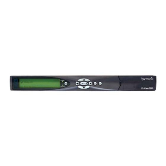
Harmonic ProView 7000 Quick Setup Manual
Integrated receiver and stream processor
Hide thumbs
Also See for ProView 7000:
- User manual (230 pages) ,
- Installation manual (37 pages) ,
- Installation manual (6 pages)
Advertisement
Quick Links
Introduction
Thank you for choosing the ProView 7000 Integrated Receiver and Stream Processor.
This document provides step-by-step instructions for quick initial setup of the ProView 7000
using the unit's front panel interface and its Element Management Software (EMS) graphical
user interface.
For detailed information on operation and configuration of the ProView 7000 platform, refer
to the ProView 7000™ Integrated Receiver and Stream Processor User Manual (Harmonic
Manual Part No. MAN-PVR-7K-2.3).
Installation and Cable Connection
Mechanical and Electrical Installation
For information about mounting, installation, electrical connection and safety precautions
refer to Chapter 2 in the ProView 7000 User Manual.
Cable Connections
All ProView 7000 connectors are located on the rear panel. Connect data, control and power
cables as required for the specific application. Connect a monitor to the unit.
© 2010 Harmonic Inc.
Integrated Receiver and Stream Processor
1
ProView 7000™
Quick Setup Guide
ProView 7000, v.2.3, Rev. A
Advertisement

Summary of Contents for Harmonic ProView 7000
- Page 1 Chapter 2 in the ProView 7000 User Manual. Cable Connections All ProView 7000 connectors are located on the rear panel. Connect data, control and power cables as required for the specific application. Connect a monitor to the unit.
-
Page 2: Initial Setup
Power Up Power Up Before powering up the ProView 7000, make sure that all cables are correctly connected. Ensure that the unit is connected to the main power supply and correctly grounded. When you power it up, you will hear the internal fans start and see the front panel LCD display light up. -
Page 3: Installing Ems
The ProView 7000 EMS The ProView 7000 EMS application provides a GUI for easy management of the ProView 7000. Most EMS functions can be performed via the front panel. You need to have an internet or LAN connection to use EMS. - Page 4 2. Click Add Device on the EMS toolbar. 3. The EMS displays the ProView 7000 Device - Add dialog. 4. Enter a name for the new ProView 7000 device. 5. Enter the IP Address of the new ProView 7000 device.
- Page 5 Device Explorer How to Configure and Monitor the ProView 7000 You can configure and monitor the ProView 7000 with either the front panel or over an IP network using the ProView 7000 EMS. Configuring the ProView 7000 using the Front Panel ■...
- Page 6 How to Configure and Monitor the ProView 7000 6. Select , (Options: MPEG and DVB). This also sets the respective PSI/SI tables 3 Input Type for the output stream. NOTE: The default option for stream type is DVB. For ATSC systems, set the stream type to MPEG.
- Page 7 Root > 2 Decoding > 1 Configuration> 4 Descrambling > 1 CAM Selection 14. Select the CAM slot. Monitoring the ProView 7000 using the Front Panel How to monitor the correct operation of the ProView 7000 device. Status OK When there are no errors the message...
- Page 8 The Alarm Monitoring screen displays a list of all active alarm messages raised by the ProView 7000 device. The information is displayed in a tabular format, providing the alarm severity level, the alarm brief description and the time the alarm was triggered.
- Page 9 How to Configure and Monitor the ProView 7000 Configuring the ProView 7000 using EMS The ProView 7000 has four logical multiplexes. A license is required for using more than one multiplex. The basic order of configuring the ProView 7000 is: 1.
- Page 10 How to Configure and Monitor the ProView 7000 iv Click in the bottom left corner of the properties dialog. Show Status The displayed properties are divided into two sections; the section on the left displays editable properties and the section on the right provides informative/status properties that cannot be edited by the EMS user.
- Page 11 How to Configure and Monitor the ProView 7000 3. To descramble a program: Right-click a program in the Multiplex & Decoding Output box. Select Properties The Program Properties dialog displays. iii Mark the Descramble with checkbox. iv Select a CAM slot.
- Page 12 How to Configure and Monitor the ProView 7000 5. To cross-connect an input transport stream, a program, an EMM in a conditional access table (CAT) or even an unreferenced PID: Drag the item from the Multiplex Input box and drop it into the Multiplex & Decoding Output box.
- Page 13 How to Configure and Monitor the ProView 7000 6. To decode a program: Drag the program name from the Multiplex Input box and drop it on the decoding channel in the Multiplex & Decoding Output box. The Decoder Channel Properties dialog displays.
- Page 14 ■ Device Communication Status The communication state of the ProView 7000 EMS with a ProView 7000 device is shown by the graphical display of the device icon in the Devices box. The alarm severity level is indicated by the device icon LEDs. A list follows with the descriptions: A device that is disconnected or not logged into is displayed in light gray.
- Page 15 The Alarms tab displays all the alarms received by the EMS from the ProView 7000 devices. Figure 1: Alarm tab To refresh the alarm list on demand: 1. Right-click any alarm in the list. 2. Select Refresh Alarms To display an alarm’s properties: 1.


Need help?
Do you have a question about the ProView 7000 and is the answer not in the manual?
Questions and answers