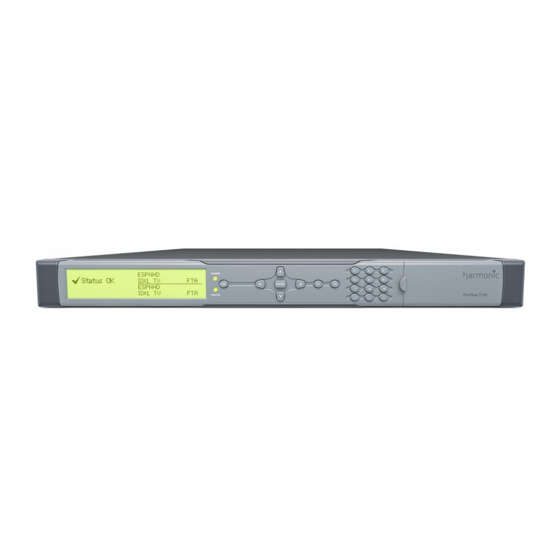
Page 1
ProView 7000/7100™ Multifunctional Receiver User Guide VERSION 2.6 Rev. E Manual Part No. MAN-PVR-7K-2.6...
Page 2
Harmonic assumes no responsibility or liability arising from the use of the products described herein, except as expressly agreed to in writing by Harmonic. The use and purchase of this product do not convey a license under any patent rights, copyrights, trademark rights, or any intellectual property rights of Harmonic.
Page 3
用手册的规定,对该产品进行使用或存储。 The Environmental Protective Use Period for Harmonic products is 20 years unless displayed otherwise on the product. The EPUP period is valid only when the products are operated or stored as per the conditions specified in the product manual.
Page 5
CAUTION: The Caution symbol calls your attention to information that, if ignored, can adversely affect the performance of your Harmonic product, or that can make a procedure needlessly difficult. LASER DANGER: The Laser symbol and the Danger alert call your attention to information about the lasers in this product that, if ignored, can cause physical harm to you.
Page 9
RGB Port Pin Configuration ......... . 185 ProView 7000™ GPI Port Pin Configuration ......186 ProView 7100™...
Page 10
Appendix C Device Explorer Icons Appendix D Front Panel Menu Tree Appendix E ProView 7000™ Alarm List Appendix F Software Management Active Version Management ......... 199 Software Upgrade Manager .
Main ProView 7000™/7100 Applications 1.2.1 TS Descrambling Applications The ProView 7000™/7100 is designed to economically meet the needs of digital turn around operators. Using its on-board quad DVB common interfaces, the ProView 7000™/7100 descrambles and re-multiplexes selected services from up to four transport streams (ProView 7000 can descramble two TSs).
MPE decapsulation for offline data delivery ■ Re-multiplexing capabilities with up to four multiplexes ■ The ProView 7000™ can generate up to four (4) TS outputs from one (1) TS input ■ Re-generation of DVB and MPEG PSI/SI ■ Low Delay decoding mode ■...
Multi-Format Decoder The ProView 7000™/7100 can be configured as a multi-format video decoder. The ProView 7000/7100 is for both Standard Definition (SD) and High Definition (HD) resolutions for MPEG-2 and MPEG-4 AVC decoding. Its wide choice of input options and video/audio interfaces ensures compatibility to all reception and decoding application environments.
Page 15
Chapter 1 Introduction ProView 7000™ Platform Main Features and Configurations License options: HD MPEG-2 / MPEG-4 AVC decoding ■ DVB-S2 upgrade (requires DVB-S2 card) ■ 2 or 4 Transport Stream routing ■ IP input ■ AAC decoding ■ Low Delay Decoding ■...
■ 1.3.3 DMS (Distribution Management System) DMS from Harmonic is a management system for video distribution networks over satellite or IP. It provides in-band / Over-The-Air (OTA) control of multiple ProView 7000™/7100 devices installed in remote locations. DMS can perform the following commands on ProView 7000™/7100 receivers: Upgrade Firmware ■...
1.4.1 ProView 7000™ Enclosure The ProView 7000™ platform is housed in a 19" 1RU mount ready enclosure. See Figure 1–1. It includes fans for right to left air passage for side-to-side heat dissipation, the ProView 7000™ may be installed in a rack without spacing between units. This allows increased flexibility for installation of a large number of units in limited space environments and integration with additional DVB equipment.
Chapter 1 Introduction ProView 7000™ Management ProView 7000™ Management The ProView 7000™ Platform provides a wide range of methods for local and remote monitoring and management: Front Panel Control The ProView 7000™/7100 front panel provides an easy to use management interface using the large LCD screen and intuitive controls.
The ProView 7000™ can be installed in a 19" rack using mounting slides. 2.1.2 Electrical connection The ProView 7000™ is powered by an AC power supply. Grounding of the ProView 7000™ is provided when the AC power cable is connected to the unit AC connector. Grounding Jackscrew When the ProView 7000™...
No Service Selected Status OK No Service Selected Configuring the IP Parameters To configure the IP parameters of a ProView 7000™: 1. Press <ENTER> on the keypad. The root menu displays. 2. Navigate Unit > Management Port > IP Configuration.
Chapter 2 Quick Start Configuring and Monitoring Configuring and Monitoring You can configure the ProView 7000™ using the front panel or remotely using EMS over the LAN. The ProView 7000™ EMS application provides a GUI for easy remote management of ProView 7000™s.
Page 22
Chapter 2 Quick Start Configuring and Monitoring To configure the ProView 7000™ using the Front Panel: 1. If the input stream is received from a satellite, navigate Root > Reception > SAT (no.) > Configuration and configure the receiver parameters according to your satellite parameters, see 4.1 Configuring the DVB-S/S2 Input Port...
Adding a Device ■ 2.4.2.1 Installing EMS The ProView 7000™ EMS is stored in the ProView 7000™ for easy installation using a web browser. To install the ProView 7000™ EMS: 1. Run a web browser and enter the ProView 7000™ IP address.
Page 26
Configuring and Monitoring 2.4.2.2 Launching EMS Prerequisites: The device IP address must be configured using the ProView 7000™ front panel, see 2.3 Configuring the IP Parameters. To launch the ProView 7000™ EMS: ❖ Double-click the Harmonic ProView 7000™ EMS launch icon to launch EMS.
2.4.3 A Typical ProView 7000™ Configuration Using EMS The ProView 7000™ has four logical multiplexes. A license is required for using more than one multiplex. Some hardware configurations support up to four satellite RF inputs. All ProView 7000™s have 2 GbE data ports.
Page 28
5. Stream and Program Routing – Drag-and-drop routing of input streams to device outputs. 6. Decoder Configuration. To configure the ProView 7000™ using EMS: 1. If the input stream is received from satellite, perform the following to display and configure a DVB-S/S2 input port: Expand the device tree in the Physical Input box to reveal the DVB in ports.
Front Panel Overview The front panel of the ProView 7000™ multifunctional receiver platform provides a managing interface for local monitoring and configuring the operation of the ProView 7000™ unit. This chapter describes the operation of the front panel interface. Topics: Main Elements and Structure ■...
Chapter 3 Front Panel Overview Front Panel Display The ProView 7100™ and ProView 7000™ front panels comprise the following: Large LCD display – The large LCD display provides enhanced menus with graphical ■ interface such as charts, radio buttons, tables and icons.
Use the <up> and <down> arrow keys to move between the branches of the tree and press <ENTER> to select and display the next lower level in the menu tree. The front panel root menu of the ProView 7000™ is a simple menu screen. To display the ProView 7000™ root menu: ❖...
Presets ■ Configuring the DVB -S/S2 Input Port Properties To configure the ProView 7000™ reception parameters: 1. Navigate Root > Reception. 2. If your device has more than one demodulator, select a satellite input menu, SAT 1–4. 3. Select Configuration.
The Decoding Main menu is enabled only when the required hardware is installed in the ProView 7000™ device. To configure the ProView 7000™ decoding parameters: ❖ Navigate Root > Decoding > Decoder (no.) > Configuration. If you only have a single decoder then their is no Decoder (no.) menu.
Service Selection Mode Use the Service Selection Mode menu to select a service selection mode. The Service Selection Mode menu comprises: Automatic Mode – Use this mode for ProView 7000 to automatically decode the first ■ program in the TS (first PMT).
Page 51
Source Specific Multicast and the Source IP Addresses are different. When the IP Address Type is Unicast, the ProView 7000™ uses the active port IP address. When the IP Address Type is Multicast, you must enter the multicast IP address. The default is 238.1.1.X (X is the socket number).
Max CAM Bitrate – 72 or 96 Mbps depending on hardware configuration. The default is 72. ■ CAM De-Jittering – Enable or disable. ■ Automatic Recovery Policy – Use to configure the ProView 7000™ to reset the CAM when ■ one of the following alarms is raised: CAM Descrambling Failure ❑...
Default Gateway – sets the network default gateway address. This is the address of a ❑ local IP router on the same network as the ProView 7000™, which is used to forward traffic beyond the local network. MAC Address – displays the media access control (MAC) address for the device.
Radio Button options: 100 and 1000 [Mbps] (Selection is not enabled. Set to 100 Mbps). 4.6.2 SW Version Menu Use the SW Version menu to display the current version of the ProView 7000™ software. 4.6.3 HW Inventory Menu Use the HW Inventory menu to display the part and version numbers of hardware modules installed in the unit.
NTP is disabled by default. 4.6.5 Set Active Version The ProView 7000™ keeps the current and last software versions. The EMS enables you to choose the active software version. The process of changing the active software version takes several minutes and requires a reboot.
Topics: Device Monitoring ■ Monitoring the DVB-S/S2 Input Port Properties ■ Monitoring the Decoding ■ Device Monitoring How to monitor the correct operation of the ProView 7000™ device. Related topics: Status OK ■ Alarms ■ 5.1.1 Status OK When there are no alarms the message...
5.1.2.2 Alarms Table The Alarms Table displays all the active alarm messages raised on the ProView 7000™. The alarm severity level, a brief description and the time the alarm was triggered display. The Alarm detailed screen provides the following information: The Alarm brief description ■...
Monitoring the DVB-S/S2 Input Port Properties Monitoring the DVB -S/S2 Input Port Properties To monitor the ProView 7000™ reception parameters: 1. Navigate Root > Reception. 2. If your device has more than one demodulator, select a satellite input menu, SAT 1–4.
The decoder type and modes of operation depend on the hardware configuration and are license dependant. The Decoding Main Menu is enabled only when the required hardware is installed in the ProView 7000™ device. The Decoding Status page comprises the following: CC Errors –...
Refreshing the EMS Screen ■ Configuring the IP Parameters Before you can manage a ProView 7000™ remotely, you must configure the IP parameters. To configure the IP parameters of a ProView 7000™: 1. Press Enter on the keypad. The root menu displays.
Internet or LAN connection ■ Installing EMS The ProView 7000™ EMS is stored in the ProView 7000™ for easy installation using a web browser. To install the ProView 7000™ EMS: 1. Run a web browser and enter the ProView 7000™ IP address.
Java -version station. Update if necessary from the Java Web start page. 2. Click Launch ProView 7000 EMS on the ProView 7000™ web page to install the EMS. The EMS application installs. Shortcuts are added to the desktop and the start menu.
7. Enter a Retry value for setting the number of connections attempts in case of a connection failure. This parameter is set to 2 tries by default. 8. Click OK to save advanced parameters. The Advanced dialog closes and the EMS returns to the Add ProView 7000™ Device dialog. 9. Click Add.
Connecting a Device Connecting a Device Connect a ProView 7000™ device to enable the EMS to monitor and control the device. A disconnected ProView 7000™ device is marked in the device list by a grayed device icon. To connect a ProView 7000™ device to the EMS: 1.
5. Click Close to complete the ping test. Disconnecting a Device A connected ProView 7000™ device is communicating with the ProView 7000™ EMS and is marked in the device list by a fully colored device icon. The icon is displayed in the Device box, and, if activated, it is also displayed in the Physical Input and Physical Output boxes.
2. Click Device Explorer in the EMS toolbar to display input and output stream trees. 6.12 EMS GUI Structure The ProView 7000™ Element Management System (EMS) is an intuitive graphical user interface (GUI) which enables you to manage ProView 7000™s over a LAN. The main EMS components are: Pull-down menus ■...
Element – Updates a branch or specific element in the stream, either at the multiplexed ■ input or the multiplexed output. Device – Updates the currently managed ProView 7000™ device. ■ To refresh an element or device: 1. Select an element or device.
To display the Device Explorer tab: ❖ Select File > Open Device Explorer and select a device from the displayed device list. —or— 1. Right-click the icon of the ProView 7000™ device in the Device Management box. The Device context menu displays. 2. Select Open Device Explorer for {ProView 7000™...
The Physical Input box on the Device Explorer tab presents a hierarchical tree-structure of the ProView 7000™ physical inputs, see Figure 6–2 for the box location. Use the Device Explorer tabs to manage streams, physical ports, multiplexes and CAMM slots.
Page 82
Port for several sockets if you define the Source Specific Multicast and the Source IP Addresses are different. When the IP Address Type is Unicast, the ProView 7000™ uses the active port IP address. When the IP Address Type is Multicast, you must enter the multicast IP address.
2. Insert the DVB-CI module into one of the two PCMCIA slots with the up arrow pointing upwards and in the direction of insertion. CAUTION: Do not remove or insert the DVB-CI module or the smart card while the ProView 7000™ is powering up or initializing.
Page 86
❑ Descrambled Programs – Displays the program PIDs descrambled by the CAM. ■ CAM Automatic Recovery Policy – You can configure the ProView 7000™ to reset the CAM ■ when one of the following alarms is raised: CAM Descrambling Failure – Enabled by default.
The Multiplex Input box of the Device Explorer tab presents a hierarchical tree-structure of the multiplex inputs of the ProView 7000™, see Figure 6–2 for the box location. It provides monitoring and configuring options for the features of each element in the tree: Input programs and elementary streams related to the multiplex input.
The Multiplex & Decoding Output box of the Device Explorer tab presents a hierarchical tree- structure of the decoded and multiplex outputs of the ProView 7000™, see Figure 6–2 for the box location. It comprises two branch types; multiplexing branches (...
Page 113
Service Selection Mode drop-down menu options: ❑ • Automatic – Use this mode for ProView 7000™ to automatically decode the first program in the TS (first PMT) • Program – Use this mode to set the decoder to manual program selection •...
■ GbE ports and sockets ■ When the Decoder module is installed in the ProView 7000™ device the module provides a wide range of physical video and audio interfaces. All interfaces are displayed under the decoder card branch. Right-click the device icon or any of the sub-elements in the Physical Output box to display a context menu which includes the following items: Table 7–4: Device Icon Context Menu...
Element Properties The Element Properties Configuration function, provided by the ProView 7000™ EMS, allows monitoring and setting ProView 7000™ properties at device level and down to specific operational elements in the device. This element can be a device selected in the Device box or any object selected on the Device Explorer tab.
CA modules. The ProView 7000™ has up to four (4) input multiplexes and up to four (4) output multiplexes. In addition, the EMS provides wizards to guide the user in creating these connections.
4. Click Create to confirm the program cross-connection. EMS Connection Wizard The ProView 7000™ EMS Connection Wizard provides EMS guided input program cross connection to any device output and device decoding channels. 1. The EMS Connection Wizard is activated from the EMS Menu tree, by selecting Actions >...
Low Delay Mode Low Delay Mode The ProView 7000 Low Delay Mode is designed to work with an Ellipse 1000/2000 encoder in Low Delay mode. The end-to-end delay should be less than 9 frames for PAL and 10 frames for NTSC. Low Delay Mode automatically detects regular video streams that do not require Low Delay Mode and treats them accordingly.
Chapter 7 Device Configuring Using EMS Device Management 7.10 Device Management To manage a ProView 7000™ device using EMS, the device must be connected. To add and connect a device, see 6.5 Adding a Device 6.7 Connecting a Device. The connected devices are listed and displayed in the Devices box. Hover the mouse pointer over a device icon to display the display tip.
7.10.5 Log-In / Log-Out Control of the Device A connected ProView 7000™ device needs to be logged-in before enabled for EMS management. The EMS user management is set at two levels: Monitoring level, where the user can view the device parameters and status.
Page 148
4. Enter a name for the preset. 5. Click OK. 7.10.7.2 Activating a Preset Use the Activate button to activate a preset in the ProView 7000™. The device reboots when you activate a preset. To activate a preset: 1. Select the device in the Devices box.
Page 149
5. Select a destination folder for the preset files. 6. Click OK. 7.10.7.6 Uploading a Preset Use the Upload button to upload a preset to a ProView 7000™. Preset files which you upload must have different names to those already in the ProView 7000™. To upload a preset: 1.
To back up the current configuration: 1. Select the device in the Devices box. 2. Select Tools > Back Up / Restore Configuration… in the ProView 7000™ EMS menu bar. The Back Up and Restore Configuration dialog displays, see Figure 7–36.
Page 151
To restore a backed-up configuration: 1. Select the device in the Devices box. 2. Select Tools > Backup/Restore Configuration… in the ProView 7000™ EMS menu bar. The Backup and Restore Configuration dialog displays, see Figure 7–36. 3. Browse the path and select the saved configuration name in the Restore Device section of the dialog.
4. Enter the access code supplied by Harmonic and click Restore. NOTE: The Harmonic supplied access code is valid for the same day only. Once the access passwords are reset to factory values, it is recommended to change and personalize them to protect the security of the device.
Chapter 7 Device Configuring Using EMS Device Properties 7.11 Device Properties Use the Device properties to monitor and set ProView 7000™ system level parameters. To display the Device properties: 1. Select a device icon in the Devices box. 2. Click Properties on the EMS toolbar.
The Hardware properties tab provides the EMS user the ability to monitor the following parameters related to the ProView 7000™ unit, arranged in the following groups / sub-tabs: NOTE: Each Hardware Properties sub-tab also displays the highest active alarm level related to the ProView 7000™...
Page 156
Chapter 7 Device Configuring Using EMS Device Properties Platform The Platform properties tab displays the following information on the ProView 7000™ platform: Part number ■ Platform serial number ■ Hardware Revision ■ Figure 7–38: Device properties dialog – Hardware – Platform tab Main Board The Main Board Properties tab displays the following ProView 7000™...
Device Communication Properties The Communications properties tab provides the EMS user the ability to manage the following parameters related to the ProView 7000™ unit communication: Traps Destination Parameters Box Traps are SNMP notifications sent by the unit to a predefined address, without user intervention.
7.11.4 Device Users’ Access Properties You can log in to ProView 7000™ devices using EMS on two levels; Configure and Monitor. The Configure defined user can monitor and configure the ProView 7000™ devices and have access to all set-up functions provided by the EMS.
7.11.5 Device Software Upgrade Properties The ProView 7000™ device software can be upgraded using non EMS managed tools, consisting of BOOTP and TFTP industry standard tools. The S/W upgrade tab sets the number of retries for each one of these two upgrade tools.
Chapter 7 Device Configuring Using EMS Device Properties 7.11.6 Device License Properties The Device License tab displays the ProView 7000™ licensed features. Figure 7–46: Device Properties dialog – License tab To enter a new license code: 1. Mark the Update license checkbox.
Chapter 8 Monitoring using EMS Use the device icon, Alarms tab and Alarms History tabs to monitor ProView 7000™ devices. Topics: Device Communication Status ■ Alarms ■ Alarm History ■ Refreshing the EMS Screen ■ DVB-S/S2 Input Port Properties Status ■...
❑ Time – Alarm generation date and time (yyyy-mm-dd hh:mm:ss format). ■ Device Name and IP – The identification name and IP address of the ProView 7000™ device ■ which have raised the alarm. Description – The alarm identification and description information.
To display the Alarm Properties dialog: 1. Right-click an alarm entry in the Alarms box. 2. Select Properties in the drop down menu. Appendix E, ProView 7000™ Alarm List for the alarm list with corrective actions. Alarm History Use the Alarms History tab to view a record of alarms triggered. You can export the alarm history in CSV format.
Element – Updates a branch or specific element in the stream, either at the multiplexed ■ input or the multiplexed output. Device – Updates the currently managed ProView 7000™ device. ■ To refresh an element or device: 1. Select an element or device.
The status properties displayed in the Status (right) section of the DVB-S/S2 In Port dialog consists of the following parameters: Carrier and Demodulator lock status – ProView 7000 attempts to lock onto a carrier even ■ when the port is not connected Carrier to noise ratio (C/N) measured value (in dBc) ■...
Chapter 9 Contacting Harmonic Support The Harmonic Customer and Technical Support groups are available to help you with any questions or problems you may have regarding Harmonic products. For assistance, refer to the following table for contact information in your region: Table 9–1: Contacting Harmonic Support...
Mode: CCM, VCM and Automatic ■ Pilots: On, Off and Automatic ■ ASI Input Connector: 2 (4 on ProView 7000™) x BNC 75 Ω ■ Packet Length: 188 and 204 byte packets ■ TS max bit rate: 160 Mbps ■...
■ B.1 Overview of Rear Panel Ports and Connectors Figure B–1 and Figure B–2 illustrate typical ProView 7000™ rear panels and Table B–1 details the ports and connectors provided on the panel. The single decoder card can be ordered with or without the genlock feature and connector.
Page 183
ASI IN 1, 2, 3 & 4 2 x ASI input stream – ProView 7100™ BNC, 75 Ω 4 x ASI input stream – ProView 7000™ ASI OUT 1, 2, 3 & 4 2 x ASI output stream – ProView 7000™...
Page 184
D-Type, 9-pin – contacts (relays) to drive external alarms ProView 7000™ 5 x dry contacts – ProView 7100™ D-Type, 15-pin female 2 x dry contacts – ProView 7000™ condensed – ProView 7100™ Power related interfaces AC Power Socket and 100–240 VAC 50/60Hz external power supply...
Appendix B Connectors and Front End Card Options ProView 7000™ GPI Port Pin Configuration B.3 ProView 7000™ GPI Port Pin Configuration Figure B–6: D-Sub 9 Pinouts Table B–3: D-Sub 9 Pinout Names Pin No. Signal N.U. 1 NO 1 COM 2...
Appendix E ProView 7000™ Alarm List The following table lists the ProView 7000™ alarms and the information provided in the properties dialog. Short Description Severity Corrective Action Backup port activated The backup port has been activated. It is recommended to revert Warning to the primary port as soon as possible.
Page 196
1. Turn off the device. 2. Contact Harmonic’s help desk. Input bitrate overflow The input bitrate to the decoder is too high. Contact Harmonic’s Major help desk. Input bitrate overflow on The input bitrate to the CAM is too high.
Page 197
Contact Harmonic’s help desk. MPEG TS Output The Output bitrate is too high. Major Overflow Reduce the bitrate or contact Harmonic’s help desk. No Genlock Sync The program cannot be decoded properly since the decoder Major could not sync to input Genlock signal.
Page 198
Appendix E ProView 7000™ Alarm List Short Description Severity Corrective Action Program Descrambling Verify that the number of programs descrambled is supported by Major Failure (output, the CAM or contact your CAM vendor. Program #) Voltage Error Contact Harmonic’s help desk.
Software Management F.1 Active Version Management The ProView 7000™ keeps the current and last software versions. The EMS enables you to choose the active software version. The process of changing the active software version takes several minutes and requires a reboot.
The Software Upgrade manager enables you to select the update file source. The manager lists all ProView 7000™ devices currently managed by the EMS and provides a checkbox to the left of each device name for you to select which devices to upgrade.
Software Upgrade Manager F.2.1 Upgrading the Firmware of ProView 7000s It is recommended to upgrade all ProView 7000™s at the same time. A device must be connected to be able to upgrade it, see 6.7 Connecting a Device. Once the device upgrade is successfully completed, the devices reboot and EMS closes.
Page 207
(such as CEA-708 and TIA-232) which has caused industry confusion. Harmonic is careful to use the current and correct names of relevant standards. Event Information Table. This table provides information in chronological order for the events contained within each service.
Page 210
MAC address The permanent identifier for a device. It consists of six octets separated by colons, for example, 00:20:A3:xx:xx:xx. The first six characters identify the manufacturer. Harmonic assigns the next six characters as a unique device identifier. Mbaud Megabaud, which is the signal rate of a line, expressed in millions. It can also be the switching speed, or number of transitions (voltage or frequency changes), per second.
Page 213
Quaternary Phase Shift Keying. QPSK transmits 2 bits at the same time by varying the phase of the signal. See also QAM. Redundancy A back-up system of Harmonic components that ensures uninterruptible service in the event of failure. component Reed-Solomon decoder A device that performs error correction on the incoming data stream.
Page 215
SNMP Simple Network Management Protocol. The protocol that Harmonic control and management systems use to configure and monitor Harmonic devices remotely over IP. Signal-to-Noise Ratio. The ratio of the amplitude (power, volume) of a data signal to the amount of noise (interference) in the line.
Page 216
The function of a transport is to contain a collection of Harmonic components, input devices, output devices, and links, and to provide access to the programs and circuits associated with that transport.
Need help?
Do you have a question about the ProView 7000 and is the answer not in the manual?
Questions and answers
Why does PER parameter flaxtuate