Sign In
Upload
Manuals
Brands
GE Manuals
Relays
L60
GE L60 Manuals
Manuals and User Guides for GE L60. We have
7
GE L60 manuals available for free PDF download: Instructions Manual, Instruction Manual, Communications Manual
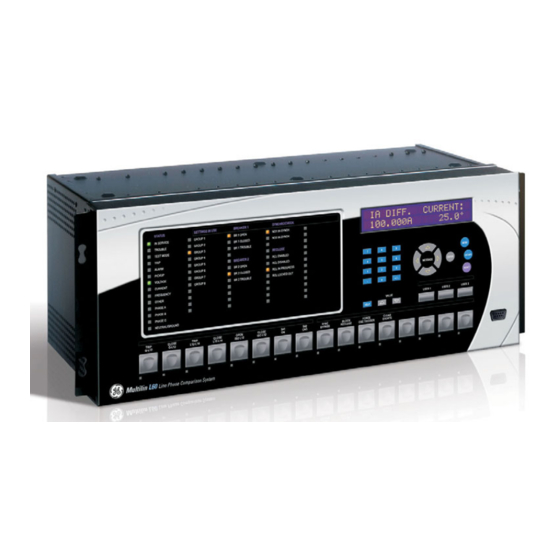
GE L60 Instruction Manual (722 pages)
Line Phase Comparison System, UR Series
Brand:
GE
| Category:
Control Unit
| Size: 12 MB
Table of Contents
Table of Contents
3
1 Getting Started
11
Important Procedures
11
Cautions and Warnings
11
Inspection Procedure
12
Ur Overview
13
Introduction to the Ur
13
Hardware Architecture
14
Software Architecture
15
Important Concepts
15
Enervista Ur Setup Software
16
Pc Requirements
16
Installation
16
Configuring the L60 for Software Access
17
Using the Quick Connect Feature
20
Connecting to the L60 Relay
26
Ur Hardware
27
Mounting and Wiring
27
Communications
27
Faceplate Display
27
Using the Relay
28
Faceplate Keypad
28
Menu Navigation
28
Menu Hierarchy
28
Relay Activation
28
Relay Passwords
29
Flexlogic™ Customization
29
Commissioning
30
2 Product Description
31
Introduction
31
Overview
31
Ordering
34
Replacement Modules
36
Specifications
39
Protection Elements
39
User-Programmable Elements
43
Monitoring
44
User-Definable Displays
44
Metering
45
Inputs
45
Power Supply
46
Outputs
46
Direct Inputs/Outputs
46
Teleprotection
46
Communication Protocols
48
Inter-Relay Communications
49
Environmental
49
Type Tests
50
Production Tests
50
Approvals
51
Maintenance
51
3 Hardware
53
Description
53
Panel Cutout
53
Rear Terminal Layout
59
Wiring
60
Typical Wiring
60
Dielectric Strength
61
Control Power
61
Ct and Vt Modules
62
Contact Inputs and Outputs
63
Transducer Inputs and Outputs
71
Rs232 Faceplate Port
73
Cpu Communication Ports
73
Irig-B
76
L60 Channel Communications
78
Direct Input and Output Communications
80
Description
80
Fiber: Led and Eled Transmitters
82
Fiber-Laser Transmitters
82
Interface
84
Rs422 Interface
87
Rs422 and Fiber Interface
89
And Fiber Interface
89
Ieee C37.94 Interface
90
C37.94Sm Interface
94
Managed Ethernet Switch Modules
98
Overview
98
Managed Ethernet Switch Module Hardware
98
Managed Switch Led Indicators
99
Initial Setup of the Ethernet Switch Module
99
Configuring the Managed Ethernet Switch Module
103
Uploading L60 Switch Module Firmware
106
Ethernet Switch Self-Test Errors
108
4 Human Interfaces
109
Enervista Ur Setup Software Interface
109
Introduction
109
Creating a Site List
109
Enervista Ur Setup Overview
109
Enervista Ur Setup Main Window
111
Extended Enervista Ur Setup Features
113
Settings Templates
113
Securing and Locking Flexlogic™ Equations
117
Settings File Traceability
119
Faceplate Interface
122
Faceplate
122
Led Indicators
123
Custom Labeling of Leds
126
Display
131
Keypad
131
Breaker Control
131
Menus
132
Changing Settings
134
5 Settings
135
Installation
135
Overview
139
Settings Menu
139
System Setup
139
Ac Inputs
139
Introduction to Elements
142
Introduction to Ac Sources
143
Product Setup
146
Security
146
Display Properties
151
Clear Relay Records
152
Communications
153
Modbus User Map
176
Real Time Clock
177
Fault Reports
178
Oscillography
180
Data Logger
182
User-Programmable Leds
183
User-Programmable Self Tests
186
Control Pushbuttons
187
Flex State Parameters
195
Power System
209
Signal Sources
210
Breakers
213
Disconnect Switches
217
Flexcurves
220
Flexlogic
227
Introduction to Flexlogic
227
Flexlogic™ Rules
238
Flexlogic™ Evaluation
238
Flexlogic™ Example
239
Flexlogic Equation Editor
243
Flexlogic Timers
243
Flexelements
244
Non-Volatile Latches
249
Grouped Elements
250
Overview
250
Setting Group
250
Phase Comparison Elements
250
Line Pickup
250
Distance
272
Power Swing Detect
290
Load Encroachment
299
Phase Current
301
Neutral Current
311
Wattmetric Ground Fault
319
Ground Current
323
Negative Sequence Current
325
Breaker Failure
332
Voltage Elements
347
Control Elements
349
Overview
349
Trip Bus
349
Setting Groups
351
Selector Switch
352
User-Programmable Pushbuttons
357
Trip Output
358
Synchrocheck
364
Digital Elements
368
Digital Counters
371
Monitoring Elements
374
Pilot Schemes
391
Autoreclose
400
Inputs/Outputs
406
Contact Inputs
406
Virtual Inputs
408
Contact Outputs
409
Virtual Outputs
411
Remote Devices
412
Remote Inputs
413
Remote Double-Point Status Inputs
414
Remote Outputs
414
Resetting
415
Direct Inputs and Outputs
416
Teleprotection Inputs and Outputs
419
Iec 61850 Goose Analogs
421
Iec 61850 Goose Integers
422
Transducer Inputs and Outputs
424
Rtd Inputs
424
Dcma Outputs
426
Test Mode
430
Force Contact Inputs
431
Force Contact Outputs
432
Advertisement
GE L60 Instructions Manual (768 pages)
Line Phase Comparison System
Brand:
GE
| Category:
Other
| Size: 32 MB
Table of Contents
Table of Contents
3
1 Introduction
11
Safety Symbols and Definitions
11
General Cautions and Warnings
11
For Further Assistance
12
2 Product Description
15
Description
16
Security
19
Order Codes
23
Replacement Modules
26
Signal Processing
28
UR Signal Processing
28
Specifications
30
Protection Elements
31
User-Programmable Elements
38
Monitoring
39
Metering
40
Inputs
41
Power Supply
43
Outputs
43
Communication Protocols
45
Inter-Relay Communications
46
Cybersentry Security
48
Graphical Front Panel
48
Environmental
48
Type Tests
49
Production Tests
50
Approvals
50
Maintenance
50
3 Installation
51
Unpack and Inspect
51
Panel Cutouts
52
Horizontal Units
52
Vertical Units
56
Rear Terminal Layout
61
Wiring
64
Typical Wiring
64
Dielectric Strength
64
Control Power
65
CT/VT Modules
66
Contact Inputs and Outputs
67
Transducer Inputs and Outputs
79
RS232 Port
81
CPU Communication Ports
82
Irig-B
84
L60 Channel Communications
85
Direct Input and Output Communications
86
Description
86
Fiber: LED and ELED Transmitters
88
Fiber Laser Transmitters
88
Interface
89
RS422 Interface
93
RS422 and Fiber Interface
95
And Fiber Interface
96
IEEE C37.94 Interface
96
C37.94SM Interface
99
Activate Relay
102
Install Software
103
Enervista Communication Overview
103
System Requirements
104
Install Software
105
Add Device to Software
106
Set IP Address in UR
107
Configure Serial Connection
112
Configure Ethernet Connection
114
Automatic Discovery of UR Devices
115
Connect to the L60
115
Connect to the L60 in Enervista
116
Use Quick Connect Via Front RS232 Port
117
Use Quick Connect Via Front USB Port
117
Use Quick Connect Via a Rear Ethernet Port
118
Set up Cybersentry and Change Default Password
118
Import Settings
119
Connect to D400 Gateway
120
Oscillography Files
120
Event Records
120
Log Files
120
Setting Files
121
4 Interfaces
123
Enervista Software Interface
123
Introduction
123
Settings Files
123
Event Viewing
124
File Support
125
Enervista Main Window
125
Protection Summary Window
126
Settings Templates
127
Secure and Lock Flexlogic Equations
131
Settings File Traceability
134
Front Panel Interface
137
Front Panel
137
Front Panel Display
139
Front Panel Navigation Keys
159
LED Indicators
160
Front Panel Labelling
165
Menu Navigation
172
Change Settings
174
View Actual Values
179
Breaker Control
180
Change Passwords
181
Invalid Password Entry
182
Logic Diagrams
183
Flexlogic Design Using Engineer
184
Design Logic
186
Send File to and from Device
196
Monitor Logic
197
View Front Panel and Print Labels
198
Generate Connectivity Report
199
Preferences
199
Toolbars
203
5 Settings
209
Settings Menu
209
Overview
212
Introduction to Elements
212
Introduction to AC Sources
213
Product Setup
216
Security
216
Display Properties
234
Graphical Front Panel
236
Clear Relay Records
248
Communications
249
Modbus User Map
316
Real-Time Clock
316
Fault Reports
321
Oscillography
323
Data Logger
325
Demand
326
User-Programmable Leds
328
User-Programmable Self-Tests
332
Control Pushbuttons
333
User-Programmable Pushbuttons
334
Flex State Parameters
340
User-Definable Displays
341
Direct Inputs and Outputs
343
Teleprotection
349
Installation
350
System Setup
350
AC Inputs
350
Power System
352
Signal Sources
353
Breakers
356
Disconnect Switch Control
361
Flexcurves
366
Flexlogic
373
Flexlogic Operands
373
Flexlogic Rules
387
Flexlogic Evaluation
388
Flexlogic Example
388
Flexlogic Equation Editor
393
Flexlogic Timers
393
Flexelements
393
Non-Volatile Latches
398
Grouped Elements
399
Overview
399
Setting Group 1
399
Phase Comparison Elements
400
Line Pickup
418
Distance
421
Power Swing Detect (ANSI 68)
441
Load Encroachment
450
Phase Current
451
Neutral Current
463
Wattmetric Ground Fault
471
Ground Current
475
Negative Sequence Current
478
Breaker Failure (ANSI 50BF)
484
Voltage Elements
494
Control Elements
503
Overview
503
Trip Bus
503
Setting Groups
505
Selector Switch
506
Trip Output
513
Synchrocheck (ANSI 25)
519
Digital Elements
524
Digital Counters
527
Monitoring Elements
529
Pilot Schemes
552
Autoreclose (ANSI 79)
554
Inputs/Outputs
568
Contact Inputs
568
Virtual Inputs
570
Contact Outputs
571
Virtual Outputs
574
Resetting
574
Direct Inputs and Outputs
575
Teleprotection
579
Transducer Inputs/Outputs
581
Dcma Inputs
581
RTD Inputs
582
Dcma Outputs
583
Testing
587
Test Mode Function
587
Test Mode Forcing
587
Force Contact Inputs
588
Force Contact Outputs
588
ge L60 Instruction Manual (690 pages)
Line Phase Comparison System
Brand:
ge
| Category:
Relays
| Size: 28 MB
Table of Contents
Table of Contents
3
1 Introduction
11
Safety Symbols and Definitions
11
General Cautions and Warnings
11
For Further Assistance
12
2 Product Description
15
Description
16
Security
19
Order Codes
22
Replacement Modules
26
Signal Processing
28
UR Signal Processing
28
Specifications
30
Protection Elements
31
User-Programmable Elements
38
Monitoring
39
Metering
40
Inputs
41
Power Supply
43
Outputs
43
Communication Protocols
45
Inter-Relay Communications
46
Cybersentry Security
48
Environmental
48
Type Tests
49
Production Tests
49
Approvals
50
Maintenance
50
3 Installation
51
Unpack and Inspect
51
Panel Cutouts
52
Horizontal Units
52
Vertical Units
53
Rear Terminal Layout
58
Wiring
59
Typical Wiring
59
Dielectric Strength
59
Control Power
60
CT/VT Modules
61
Contact Inputs and Outputs
62
Transducer Inputs and Outputs
69
RS232 Faceplate Port
71
CPU Communication Ports
72
Irig-B
74
L60 Channel Communications
75
Direct Input and Output Communications
77
Description
77
Fiber: LED and ELED Transmitters
79
Fiber Laser Transmitters
79
Interface
80
RS422 Interface
84
RS422 and Fiber Interface
86
And Fiber Interface
87
IEEE C37.94 Interface
87
C37.94SM Interface
90
Activate Relay
93
Install Software
94
Enervista Communication Overview
94
System Requirements
95
Install Software
96
Add Device to Software
97
Set IP Address in UR
97
Configure Serial Connection
103
Configure Ethernet Connection
104
Automatic Discovery of UR Devices
106
Connect to the L60
106
Connect to the L60 in Enervista
107
Use Quick Connect Via the Front Panel RS232 Port
108
Use Quick Connect Via a Rear Ethernet Port
108
Set up Cybersentry and Change Default Password
109
Import Settings
110
4 Interfaces
111
Enervista Software Interface
111
Introduction
111
Settings Files
111
Event Viewing
112
File Support
113
Enervista Main Window
113
Protection Summary Window
114
Settings Templates
115
Secure and Lock Flexlogic Equations
119
Settings File Traceability
122
Front Panel Interface
125
Front Panel Display
125
Front Panel Keypad
126
Menu Navigation
126
Menu Hierarchy
126
Changing Settings
127
Faceplate
129
LED Indicators
130
Custom LED Labeling
134
Breaker Control
139
Change Passwords
140
Invalid Password Entry
141
Logic Diagrams
142
Flexlogic Design and Monitoring Using Engineer
143
Design Logic
145
Send File to and from Device
155
Monitor Logic
156
View Front Panel and Print Labels
157
Generate Connectivity Report
158
Preferences
158
Toolbars
162
5 Settings
169
Settings Menu
169
Overview
172
Introduction to Elements
172
Introduction to AC Sources
173
Product Setup
176
Security
176
Display Properties
194
Clear Relay Records
196
Communications
197
Modbus User Map
261
Real-Time Clock
262
Fault Reports
266
Oscillography
268
Data Logger
270
Demand
271
User-Programmable Leds
273
User-Programmable Self-Tests
276
Control Pushbuttons
277
User-Programmable Pushbuttons
278
Flex State Parameters
283
User-Definable Displays
284
Direct Inputs and Outputs
286
Teleprotection
292
Installation
293
System Setup
293
AC Inputs
293
Power System
295
Signal Sources
296
Breakers
298
Disconnect Switches
303
Flexcurves
306
Flexlogic
313
Flexlogic Operands
313
Flexlogic Rules
326
Flexlogic Evaluation
326
Flexlogic Example
327
Flexlogic Equation Editor
332
Flexlogic Timers
332
Flexelements
332
Non-Volatile Latches
336
Grouped Elements
337
Overview
337
Setting Group 1
337
Phase Comparison Elements
338
Line Pickup
356
Distance
359
Power Swing Detect (ANSI 68)
379
Load Encroachment
388
Phase Current
389
Neutral Current
401
Wattmetric Ground Fault
409
Ground Current
413
Negative Sequence Current
416
Breaker Failure (ANSI 50BF)
422
Voltage Elements
432
Control Elements
441
Overview
441
Trip Bus
441
Setting Groups
443
Selector Switch
444
Trip Output
451
Synchrocheck (ANSI 25)
457
Digital Elements
462
Digital Counters
465
Monitoring Elements
467
Pilot Schemes
490
Autoreclose (ANSI 79)
492
Inputs/Outputs
506
Contact Inputs
506
Virtual Inputs
508
Contact Outputs
509
Virtual Outputs
512
Resetting
512
Direct Inputs and Outputs
513
Teleprotection
516
Transducer Inputs/Outputs
518
Dcma Inputs
518
RTD Inputs
519
Dcma Outputs
520
Testing
524
Test Mode Function
524
Test Mode Forcing
524
Force Contact Inputs
525
Force Contact Outputs
525
Advertisement
GE L60 Instruction Manual (578 pages)
Line Phase Comparison Relay, UR Series
Brand:
GE
| Category:
Relays
| Size: 10 MB
Table of Contents
Table of Contents
5
1 Getting Started
13
Important Procedures
13
Cautions and Warnings
13
Inspection Checklist
13
Ur Overview
14
Introduction to the Ur
14
Hardware Architecture
15
Software Architecture
16
Important Concepts
16
Enervista Ur Setup Software
17
Pc Requirements
17
Installation
17
Configuring the L60 for Software Access
18
Using the Quick Connect Feature
21
Connecting to the L60 Relay
27
Ur Hardware
28
Mounting and Wiring
28
Communications
28
Faceplate Display
28
Using the Relay
29
Faceplate Keypad
29
Menu Navigation
29
Menu Hierarchy
29
Relay Activation
29
Battery Tab
30
Relay Passwords
30
Flexlogic™ Customization
30
Commissioning
31
2 Product Description
33
Introduction
33
Overview
33
Ordering
36
Replacement Modules
39
Specifications
41
Protection Elements
41
User-Programmable Elements
45
Monitoring
46
Metering
46
Inputs
47
Power Supply
48
Outputs
48
Communications
49
Inter-Relay Communications
50
Environmental
50
Type Tests
51
Production Tests
51
Approvals
51
Maintenance
51
3 Hardware
53
Description
53
Panel Cutout
53
Module Withdrawal and Insertion
56
Rear Terminal Layout
57
Wiring
58
Typical Wiring
58
Dielectric Strength
59
Control Power
59
Ct/Vt Modules
60
Contact Inputs/Outputs
62
Transducer Inputs/Outputs
70
Rs232 Faceplate Port
71
Cpu Communication Ports
71
Irig-B
74
L60 Channel Communications
75
Direct Input/Output Communications
76
Description
76
Fiber: Led and Eled Transmitters
78
Fiber-Laser Transmitters
78
Interface
79
Rs422 Interface
82
Rs422 and Fiber Interface
84
And Fiber Interface
84
Ieee C37.94 Interface
85
C37.94Sm Interface
87
4 Human Interfaces
89
Enervista Ur Setup Software Interface
89
Introduction
89
Creating a Site List
89
Enervista Ur Setup Overview
89
Enervista Ur Setup Main Window
91
Faceplate Interface
92
Faceplate
92
Led Indicators
93
Display
96
Keypad
96
Breaker Control
96
Menus
97
Changing Settings
99
5 Settings
99
Overview
103
Settings Main Menu
103
Introduction to Elements
106
Introduction to Ac Sources
107
Product Setup
110
Password Security
110
Display Properties
111
Clear Relay Records
113
Communications
114
Modbus User Map
129
Real Time Clock
130
Fault Reports
131
Oscillography
133
Data Logger
135
User-Programmable Leds
136
User-Programmable Self Tests
139
Control Pushbuttons
140
User-Programmable Pushbuttons
141
Flex State Parameters
145
User-Definable Displays
145
Direct Inputs/Outputs
147
Teleprotection
152
Installation
153
System Setup
154
Ac Inputs
154
Power System
156
Signal Sources
157
Breakers
159
Flexcurves
162
Flexlogic
169
Introduction to Flexlogic
169
Flexlogic™ Rules
179
Flexlogic™ Evaluation
179
Flexlogic™ Example
179
Flexlogic Equation Editor
184
Flexlogic™ Timers
184
Non-Volatile Latches
189
Grouped Elements
190
Overview
190
Setting Group
190
Phase Comparison Elements
190
Line Pickup
205
Distance
207
Power Swing Detect
227
Load Encroachment
233
Phase Current
235
Neutral Current
245
Wattmetric Ground Fault
253
Ground Current
256
Negative Sequence Current
257
Breaker Failure
264
Voltage Elements
273
Control Elements
281
Overview
281
Setting Groups
281
Selector Switch
282
Trip Output
288
Synchrocheck
292
Digital Elements
296
Digital Counters
299
Monitoring Elements
301
Pilot Schemes
312
Autoreclose
315
Autoreclose
321
Inputs/Outputs
327
Contact Inputs
327
Virtual Inputs
329
Contact Outputs
330
Virtual Outputs
332
Remote Devices
333
Remote Inputs
334
Remote Outputs
335
Resetting
336
Direct Inputs/Outputs
336
Teleprotection Inputs/Outputs
340
Transducer Inputs/Outputs
342
Dcma Inputs
342
Rtd Inputs
343
Dcma Outputs
343
Testing
347
Test Mode
347
Force Contact Inputs
347
Force Contact Outputs
348
GE L60 Instruction Manual (498 pages)
UR Series Line Phase Comparison Relay
Brand:
GE
| Category:
Relays
| Size: 10 MB
Table of Contents
Table of Contents
5
1 Getting Started
11
Important Procedures
11
Cautions and Warnings
11
Inspection Checklist
11
Ur Overview
12
Introduction to the Ur
12
Hardware Architecture
13
Software Architecture
14
Important Concepts
14
Enervista Ur Setup Software
15
Pc Requirements
15
Installation
15
Connecting Enervista Ur Setup with the L60
17
Ur Hardware
20
Mounting and Wiring
20
Communications
20
Faceplate Display
20
Using the Relay
21
Faceplate Keypad
21
Menu Navigation
21
Menu Hierarchy
21
Relay Activation
22
Battery Tab
22
Relay Passwords
22
Flexlogic™ Customization
22
Commissioning
23
2 Product Description
25
Introduction
25
Overview
25
Ordering
28
Specifications
32
Protection Elements
32
User-Programmable Elements
35
Monitoring
36
Metering
36
Inputs
37
Power Supply
37
Outputs
38
Communications
39
Inter-Relay Communications
40
Environmental
40
Type Tests
41
Production Tests
41
Approvals
41
Maintenance
41
3 Hardware
43
Description
43
Panel Cutout
43
Module Withdrawal and Insertion
46
Rear Terminal Layout
47
Wiring
48
Typical Wiring
48
Dielectric Strength
49
Control Power
49
Ct/Vt Modules
50
Contact Inputs/Outputs
52
Transducer Inputs/Outputs
59
Rs232 Faceplate Port
60
Cpu Communication Ports
60
Irig-B
63
L60 Channel Communications
64
Direct Input/Output Communications
65
Description
65
Fiber: Led and Eled Transmitters
67
Fiber-Laser Transmitters
67
Interface
68
Rs422 Interface
71
Rs422 and Fiber Interface
73
And Fiber Interface
73
Ieee C37.94 Interface
74
C37.94Sm Interface
76
4 Human Interfaces
79
Enervista Ur Setup Software Interface
79
Introduction
79
Creating a Site List
79
Enervista Ur Setup Software Overview
79
Enervista Ur Setup Software Main Window
81
Faceplate Interface
82
Faceplate
82
Led Indicators
83
Display
86
Keypad
86
Breaker Control
86
Menus
87
Changing Settings
89
5 Settings
89
Overview
93
Settings Main Menu
93
Introduction to Elements
96
Introduction to Ac Sources
97
Product Setup
100
Password Security
100
Display Properties
101
Clear Relay Records
103
Communications
104
Modbus User Map
114
Real Time Clock
114
Fault Reports
115
Oscillography
116
Data Logger
118
User-Programmable Leds
119
User-Programmable Self Tests
122
Control Pushbuttons
123
User-Programmable Pushbuttons
124
Flex State Parameters
125
User-Definable Displays
126
Direct Inputs/Outputs
128
Teleprotection
133
Installation
134
System Setup
135
Ac Inputs
135
Power System
137
Signal Sources
138
Breakers
140
Flexcurves
143
Flexlogic
150
Introduction to Flexlogic
150
Flexlogic™ Rules
159
Flexlogic™ Evaluation
159
Flexlogic™ Example
160
Flexlogic Equation Editor
164
Non-Volatile Latches
169
Grouped Elements
170
Overview
170
Setting Group
170
Phase Comparison Elements
170
Line Pickup
178
Distance
180
Power Swing Detect
198
Load Encroachment
206
Phase Current
208
Neutral Current
218
Ground Current
226
Negative Sequence Current
228
Breaker Failure
234
Voltage Elements
243
Control Elements
249
Overview
249
Setting Groups
249
Selector Switch
250
Trip Output
256
Synchrocheck
260
Digital Elements
264
Digital Counters
267
Monitoring Elements
269
Pilot Schemes
280
Autoreclose
288
Inputs/Outputs
295
Contact Inputs
295
Virtual Inputs
297
Contact Outputs
298
Virtual Outputs
300
Remote Devices
301
Remote Inputs
302
Remote Outputs
303
Resetting
304
Direct Inputs/Outputs
304
Teleprotection Inputs/Outputs
308
Transducer Inputs/Outputs
310
Dcma Inputs
310
Rtd Inputs
311
Dcma Outputs
311
Testing
315
Test Mode
315
Force Contact Inputs
315
Force Contact Outputs
316
GE L60 Communications Manual (532 pages)
Universal Relay Family
Brand:
GE
| Category:
Relays
| Size: 3 MB
Table of Contents
Table of Contents
3
1 Introduction
7
Products
7
Features Per Product
7
Communication Ports
20
Safety Symbols and Definitions
20
For Further Assistance
20
Modbus
21
2 Modbus Communication
21
Modbus RTU Protocol
21
Introduction
21
Configuration
21
Physical Layer
21
Data Link Layer
22
Modbus RTU CRC-16 Algorithm
23
Modbus Function Codes
24
Supported Function Codes
24
Read Actual Values or Settings (Function Code 03/04H)
24
Execute Operation (Function Code 05H)
25
Store Single Setting (Function Code 06H)
25
Store Multiple Settings (Function Code 10H)
26
Exception Responses
26
File Transfers
27
Obtaining Relay Files Using Modbus
27
Memory Map
32
Modbus Memory Map
32
6 Iec 60870-5-104
80
Communication
81
Data Formats
204
3 Iec 61850 Communication
239
Overview
239
Introduction
239
Abstract Communication Service Interface (ASCI)
241
Datasets
244
Txgoose
245
Rxgoose
247
Reports
248
Commands
250
Substation Configuration Language (SCL)
250
Configuring the UR Using SCL
256
Merge SCL File
261
Configurable Logical Devices
262
Protocol Implementation Conformance Statement (PICS)
262
Basic Conformance Statement
262
ACSI Conformance Statement
263
ACSI Basic Conformance Statement
263
ACSI Models Conformance Statement
263
ACSI Services Conformance Statement
265
Model Implementation Conformance Statement (MICS)
267
Master (Root) Logical Device
268
Protection (Prot) Logical Device
275
Control (Ctrl) Logical Device
354
System Logical Device
389
Meter Logical Device
410
General (Gen) Logical Device
431
GE Namespace
447
Enumerations
462
SCL Implementation Conformance Statement (SICS)
463
PIXIT Conformance Statement
465
TICS Conformance Statement
470
SCL Logging
472
Overview of Process
472
SCL File Storage on UR
473
Generation of CID Files
473
Schema Version Used by Ur/Enervista
473
CID File Processing Steps
473
SCL Log File Format and Examples
473
Troubleshooting Log File Errors
475
G2 Implementation Model for GOOSE Configuration Via SCL
475
Introduction
475
Configuration Process
476
Configuration Process with IED Setup Tool
478
IED Capability Description (ICD) File
478
Instantiated IED Capability Description (IID) File
482
Configured IED Description (CID) File
482
Sample SCL Files
484
Annex - Optional Intermediate GOOSE Reception Objects
489
E3-2.0 Implementation Model for GOOSE Configuration Via SCL
492
Introduction
492
Workflow
492
ICD Files
493
CID Files
494
IID Files
495
GE L60 Communications Manual (526 pages)
UR Family
Brand:
GE
| Category:
Controller
| Size: 3 MB
Table of Contents
Table of Contents
3
1 Introduction
7
Products
7
Features Per Product
7
Communication Ports
20
Safety Symbols and Definitions
20
For Further Assistance
20
Modbus
21
2 Modbus Communication
21
Modbus RTU Protocol
21
Introduction
21
Configuration
21
Physical Layer
21
Data Link Layer
22
Modbus RTU CRC-16 Algorithm
23
Modbus Function Codes
24
Supported Function Codes
24
Read Actual Values or Settings (Function Code 03/04H)
24
Execute Operation (Function Code 05H)
25
Store Single Setting (Function Code 06H)
25
Store Multiple Settings (Function Code 10H)
26
Exception Responses
26
File Transfers
27
Obtaining Relay Files Using Modbus
27
Memory Map
32
Modbus Memory Map
32
6 Iec 60870-5-104
80
Communication
81
Data Formats
203
3 Iec 61850 Communication
239
Overview
239
Introduction
239
Abstract Communication Service Interface (ASCI)
241
Datasets
244
Txgoose
245
Rxgoose
247
Reports
248
Commands
250
Substation Configuration Language (SCL)
250
Configuring the UR Using SCL
256
Merge SCL File
261
Configurable Logical Devices
262
Protocol Implementation Conformance Statement (PICS)
262
Basic Conformance Statement
262
ACSI Conformance Statement
263
ACSI Basic Conformance Statement
263
ACSI Models Conformance Statement
263
ACSI Services Conformance Statement
265
Model Implementation Conformance Statement (MICS)
267
Master (Root) Logical Device
268
Protection (Prot) Logical Device
275
Control (Ctrl) Logical Device
351
System Logical Device
385
Meter Logical Device
406
General (Gen) Logical Device
426
GE Namespace
442
Enumerations
457
SCL Implementation Conformance Statement (SICS)
458
PIXIT Conformance Statement
460
TICS Conformance Statement
465
SCL Logging
467
Overview of Process
467
SCL File Storage on UR
468
Generation of CID Files
468
Schema Version Used by Ur/Enervista
468
CID File Processing Steps
468
SCL Log File Format and Examples
468
Troubleshooting Log File Errors
470
G2 Implementation Model for GOOSE Configuration Via SCL
470
Introduction
470
Configuration Process
471
Configuration Process with IED Setup Tool
473
IED Capability Description (ICD) File
473
Instantiated IED Capability Description (IID) File
477
Configured IED Description (CID) File
477
Sample SCL Files
479
Annex - Optional Intermediate GOOSE Reception Objects
484
E3-2.0 Implementation Model for GOOSE Configuration Via SCL
487
Introduction
487
Workflow
487
ICD Files
488
CID Files
489
IID Files
490
Advertisement
Related Products
GE L90
GE LPS-O
GE LPSOB35U23VE1N
GE LPS-D
GE LP 33U Series
GE Digital Energy LP 31 Series
GE LOGIQ i
GE LOGIC V5 Venue
GE LOGIQ LP6 PRO P.B.VOLUSON LA110
GE Lumination LDXB Series
GE Categories
Refrigerator
Ranges
Microwave Oven
Dishwasher
Air Conditioner
More GE Manuals
Login
Sign In
OR
Sign in with Facebook
Sign in with Google
Upload manual
Upload from disk
Upload from URL