Sign In
Upload
Manuals
Brands
Circutor Manuals
Measuring Instruments
CVM-C11
User Manuals: Circutor CVM-C11 Power Analyzer
Manuals and User Guides for Circutor CVM-C11 Power Analyzer. We have
2
Circutor CVM-C11 Power Analyzer manuals available for free PDF download: Instruction Manual
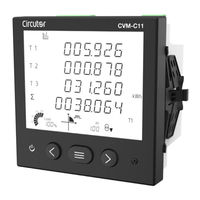
Circutor CVM-C11 Instruction Manual (134 pages)
Power analyzer
Brand:
Circutor
| Category:
Measuring Instruments
| Size: 14 MB
Table of Contents
Safety Precautions
3
Disclaimer
3
Table of Contents
4
Contents
4
Revision Log
7
Symbols
7
1�- Verification Upon Reception
8
2�- Product Description
8
3�- Device Installation
9
3�1�- Prior Recommendations
9
3�2�- Installation
9
3�3�- CVM-C11-Flex-In-485-Ict2: Rogowski Sensors
10
3�4�- Device Terminals
11
3�4�1�- CVM-C11-Itf-In-485-Ict2 and CVM-C11-MC-In-485-Ict2 Models
11
3�4�2�- CVM-C11-Itf-In-Eth-Ict2 Model
12
3�4�3�- CVM-C11-Flex-In-485-Ict2 Model
13
3�5�- Connection Diagram
14
3�5�1�- MEASURING THREE-PHASE NETWORKS with a 4-WIRE CONNECTION, CVM-C11-ITF-IN-XXX-ICT2
14
Model
14
3�5�2�- Measuring Three-Phase Networks with a 4-Wire Connection, CVM-C11-MC-In-485-Ict2
15
Model
15
3�5�3�- Measuring Three-Phase Networks with a 4-Wire Connection, CVM-C11-Flex-In-485-Ict2
16
Model
16
3�5�4�- MEASURING THREE-PHASE NETWORKS with a 3-WIRE CONNECTION, CVM-C11-ITF-IN-XXX-ICT2
17
Model
17
3�5�5�- Measuring Three-Phase Networks with a 3-Wire Connection, CVM-C11-MC-In-485-Ict2
18
Model
18
3�5�6�- Measuring Three-Phase Networks with a 3-Wire Connection, CVM-C11-Flex-In-485-Ict2
19
Model
19
3�5�7�- MEASURING THREE-PHASE NETWORKS with a 3-WIRE CONNECTION and TRANSFORMERS with an ARON CONNECTION, CVM-C11-ITF-IN-XXX-ICT2 MODELS
20
3�5�8�- Measuring Three-Phase Networks with a 3-Wire Connection and Transformers with an Aron Connection, CVM-C11-MC-In-485-Ict2 Model
21
3�5�9�- Measuring Three-Phase Networks with a 3-Wire Connection and Transformers with an Aron Connection, CVM-C11-Flex-In-485-Ict2 Model
22
Model
22
Models
23
3�5�12�- Measuring Two-Phase Networks with a 3-Wire Connection, CVM-C11-Flex-In-485-Ict2
25
Model
25
CVM-C11-ITF-IN-XXX-ICT2 MODELS
26
CVM-C11-MC-In-485-Ict2 Model
27
CVM-C11-Flex-In-485-Ict2 Model
28
CVM-C11-ITF-IN-XXX-ICT2 MODELS
29
CVM-C11-MC-In-485-Ict2 Model
30
CVM-C11-Flex-In-485-Ict2 Model
31
CVM-C11-ITF-IN-XXX-ICT2 MODELS
32
CVM-C11-MC-In-485-Ict2 Model
33
3�5�21�- Measuring Three-Phase Networks with a 3-Wire and Earth Connection
34
CVM-C11-Flex-In-485-Ict2 Model
34
4�- Operation
35
4�1�- Measuring Parameters
36
4�1�1�- Thd Calculation
41
4�1�2�- Maximum Demand
41
4�2�- Display
42
4�2�1�- Cos Φ - PF (POWER FACTOR)
43
4�2�2�- Analogue Bar
43
4�3�- Keyboard Functions
44
4�4�- Led Indicators
46
4�5�- Relays
46
4�6�- Digital Inputs
47
4�7�- Digital Outputs
47
5�- Display
48
5�1�- Analyzer Profile
48
5�1�1�- Maximum and Minimum Values
50
5�1�2�- Maximum Demand
51
5�1�3�- Detection of Incorrect Direction of Rotation
52
Profile
52
5�3�- User Profile
54
5�4�- Harmonics
55
6�- Configuration
56
6�1�- Primary Voltage
57
6�2�- Secondary Voltage
58
6�3�- Primary Current
59
6�4�- SECONDARY CURRENT (CVM-C11-ITF-IN-XXX-ICT2 Model)
59
6�5�- Primary Neutral Current
60
6�6�- SECONDARY NEUTRAL CURRENT (CVM-C11-ITF-IN-XXX-ICT2 Model)
61
6�7�- Number of Quadrants
61
6�8�- Measurement Convention
62
6�9�- Type of Installation
63
6�10�- Type of Integration of the Maximum Demand
63
6�11�- Maximum Demand Integration Period
64
6�12�- Deleting Maximum Demand
65
6�13�- Thd Calculation
65
6�14�- Selecting the Operation Profile
66
6�14�1�- Selecting the Screens that will be Displayed
66
6�14�2�- Selecting the Screens
67
6�15�- Backlight, Turning on the Backlit Display
68
6�16�- DISPLAY SELECTION Cos Φ - PF
69
6�17�- Deleting Maximum and Minimum Values
69
6�18�- Deleting Energy Values
70
6�19�- Selecting the Range of Energies
71
6�20�- Activating the Harmonics Display Screen
71
Carbon Emission Ratio of Consumed Energy
72
6�22�- Kgc0 2 CARBON EMISSION RATIO of GENERATED ENERGY
73
6�23�- Cost Ratio of Consumed Energy
74
6�24�- Cost Ratio of Generated Energy
74
6�25�- Programming the Alarm Relay 1
75
6�25�1�- Maximum Value
77
6�25�2�- Minimum Value
78
6�25�3�- Connection Time Delay
78
6�25�4�- Hysteresis Value
79
6�25�5�- Latch
80
6�25�6�- Disconnection Delay
80
6�25�7�- Contact Status
81
6�26�- Programming the Alarm Relay 2
81
6�27�- Programming Alarm 3 (Digital Output T1)
82
6�27�1�- Kilowatts Per Pulse
83
6�27�2�- Pulse Width
84
6�28�- Programming Alarm 4 (Digital Output T2)
84
6�29�- Operating Mode of Digital Input 1
85
6�30�- Operating Mode of Digital Input 2
85
6�31�- Rs-485 Communications: Protocol
86
6�32�- Modbus Protocol: Baud Rate
87
6�33�- Modbus Protocol: Peripheral Number
87
6�34�- Modbus Protocol: Parity
88
6�35�- Modbus Protocol: Number of Data Bits
89
6�36�- Modbus Protocol: Number of Stop Bits
89
6�37�- Bacnet PROTOCOL: BAUD RATE
90
6�38�- Bacnet PROTOCOL: DEVICE ID
90
6�39�- Bacnet PROTOCOL: MAC ADDRESS
91
6�40�- Locking the Programming
92
6�40�1�- Password
92
7�- Configuration of Ethernet Communications
94
7�1�- Protocol
94
7�2�- Modbus Tcp Protocol: Dhcp
95
7�3�- Modbus Tcp Protocol: Ip Adress
95
7�4�- Modbus Tcp Protocol: Mask
96
7�5�- Modbus Tcp Protocol: Gateway
97
7�6�- Modbus Tcp Protocol: Mac Adress
97
7�7�- Modbus Tcp Protocol: Port
98
7�8�- Bacnet Protocol: Port
98
8�- Rs-485 Communications
99
8�1�- Connections
99
8�2�- Modbus Protocol
100
8�2�1�- READING EXAMPLE: FUNCTION 0X04
100
8�2�2�- WRITING EXAMPLE: FUNCTION 0X05
100
8�3�- Modbus Commands
101
8�3�1�- Measurement Variables
101
8�3�2�- Energy Variables
102
8�3�3�- Voltage and Current Harmonics
103
8�3�4�- Deleting Parameters
104
8�3�5�- Power Status
105
8�3�6�- the Device's Serial Number
105
8�3�7�- Detection of Incorrect Direction of Rotation
105
8�3�8�- Status of Inputs and Outputs
105
8�3�9�- Device Configuration Variables
106
8�4�- Bacnet PROTOCOL
111
8�4�1�- Mapa Pics
112
9�- Technical Features
116
10�- Maintenance and Technical Service
120
11�- Guarantee
120
12�- Eu Declaration of Conformity
121
Annex A.- Configuration Menus
124
Annex A�1�- Selecting the Operation Profile
128
Annex A�2�- Programming the Alarm Relay 1 Amd 2
129
Annex A�3�- Programming Alarm 3 and 4
130
Annex A�4�- Rs-485 Communications Programming
131
Annex A�5�- Locking the Programming
132
Annex B.- Ethernet Configuration Menus
133
Advertisement
Circutor CVM-C11 Instruction Manual (106 pages)
Power analyzer
Brand:
Circutor
| Category:
Measuring Instruments
| Size: 12 MB
Table of Contents
Safety Precautions
3
Disclaimer
3
Table of Contents
4
Contents
4
Revision Log
6
Symbols
6
1�- Verification Upon Reception
7
2�- Product Description
7
3�- Device Installation
8
3�1�- Prior Recommendations
8
3�2�- Installation
8
3�3�- Device Terminals
9
3�4�- Connection Diagram
10
3�4�1�- Measuring Three-Phase Networks with a 4-Wire Connection
10
3�4�2�- Measuring Three-Phase Networks with a 3-Wire Connection
11
Aron Connection
12
3�4�4�- Measuring Two-Phase Networks with a 3-Wire Connection
13
3�4�5�- Measuring Single-Phase Networks, Phase to Phase, with a 2-Wire Connection
14
3�4�6�- Measuring Single-Phase Networks, Phase to Neutral, with a 2-Wire Connection
15
4�- Operation
16
4�1�- Measuring Parameters
17
4�1�1�- Thd Calculation
21
4�1�2�- Maximum Demand
22
4�2�- Display
23
4�2�1�- Cos Φ - PF (POWER FACTOR)
24
4�2�2�- Analogue Bar
24
4�3�- Keyboard Functions
25
4�4�- Led Indicators
26
4�5�- Relays
27
4�6�- Digital Inputs
27
4�7�- Digital Outputs
28
5�- Display
29
5�1�- Analyzer Profile
29
5�1�1�- Maximum and Minimum Values
31
5�1�2�- Maximum Demand
32
5�1�3�- Detection of Incorrect Direction of Rotation
33
5�2�- E 3 PROFILE
33
5�3�- User Profile
35
5�4�- Harmonics
35
6�- Configuration
37
6�1�- Primary Voltage
38
6�2�- Secondary Voltage
39
6�3�- Primary Current
39
6�4�- Secondary Current
40
6�5�- Primary Neutral Current
41
6�6�- Secondary Neutral Current
41
6�7�- Number of Quadrants
42
6�8�- Measurement Convention
43
6�9�- Type of Installation
43
6�10�- Type of Integration of the Maximum Demand
44
6�11�- Maximum Demand Integration Period
45
6�12�- Deleting Maximum Demand
46
6�13�- Thd Calculation
46
6�14�- Selecting the Operation Profile
47
6�14�1�- Selecting the Screens that will be Displayed
47
6�14�2�- Selecting the Screens
48
6�15�- Backlight, Turning on the Backlit Display
49
6�16�- DISPLAY SELECTION Cos Φ - PF
50
6�17�- Deleting Maximum and Minimum Values
50
6�18�- Deleting Energy Values
51
6�19�- Selecting the Range of Energies
51
6�20�- Activating the Harmonics Display Screen
52
Carbon Emission Ratio of Consumed Energy
53
6�22�- Kgc0 2 CARBON EMISSION RATIO of GENERATED ENERGY
53
6�23�- Cost Ratio of Consumed Energy
54
6�24�- Cost Ratio of Generated Energy
55
6�25�- Programming the Alarm Relay 1
56
6�25�1�- Maximum Value
57
6�25�2�- Minimum Value
58
6�25�3�- Connection Time Delay
59
6�25�4�- Hysteresis Value
60
6�25�5�- Latch
60
6�25�6�- Disconnection Delay
61
6�25�7�- Contact Status
62
6�26�- Programming the Alarm Relay 2
62
6�27�- Programming Alarm 3 (Digital Output T1)
62
6�27�1�- Kilowatts Per Pulse
63
6�27�2�- Pulse Width
64
6�28�- Programming Alarm 4 (Digital Output T2)
65
6�29�- Operating Mode of Digital Input 1
65
6�30�- Operating Mode of Digital Input 2
66
6�31�- Rs-485 Communications: Protocol
67
6�32�- Modbus Protocol: Baud Rate
67
6�33�- Modbus Protocol: Peripheral Number
68
6�34�- Modbus Protocol: Parity
69
6�35�- Modbus Protocol: Number of Data Bits
69
6�36�- Modbus Protocol: Number of Stop Bits
70
6�37�- Bacnet PROTOCOL: BAUD RATE
70
6�38�- Bacnet PROTOCOL: DEVICE ID
71
6�39�- Bacnet PROTOCOL: MAC ADDRESS
72
6�40�- Locking the Programming
72
6�40�1�- Password
73
7�- Communications
74
7�1�- Connections
74
7�2�- Modbus Protocol
75
7�2�1�- READING EXAMPLE: FUNCTION 0X04
75
7�2�2�- WRITING EXAMPLE: FUNCTION 0X05
75
7�3�- Modbus Commands
76
7�3�1�- Measurement Variables
76
7�3�2�- Energy Variables
77
7�3�3�- Voltage and Current Harmonics
78
7�3�4�- Deleting Parameters
79
7�3�5�- Power Status
80
7�3�6�- the Device's Serial Number
80
7�3�7�- Detection of Incorrect Direction of Rotation
80
7�3�8�- Device Configuration Variables
80
7�4�- Bacnet PROTOCOL
86
7�4�1�- Mapa Pics
87
8�- Technical Features
90
9�- Maintenance and Technical Service
93
10�- Guarantee
93
11�- Eu Declaration of Conformity
94
Annex A.- Configuration Menus
97
Annex A�1�- Selecting the Operation Profile
101
Annex A�2�- Programming the Alarm Relay 1 Amd 2
102
Annex A�3�- Programming Alarm 3 and 4
103
Annex A�4�- Rs-485 Communications Programming
104
Annex A�5�- Locking the Programming
105
Advertisement
Related Products
Circutor CVM-C10
Circutor CVM-C5-IC
Circutor CVM-C5-MC-IC
Circutor CVM-C5-mV-IC
Circutor CVM-C4 Series
Circutor CVM-C5 Series
Circutor CVM-C5-ITF-485
Circutor CVM-C5-MC-485
Circutor CVM-C5-mV-485
Circutor CVM-C11-ITF-IN-485-ICT2
Circutor Categories
Measuring Instruments
Relays
Automobile Accessories
Battery Charger
Controller
More Circutor Manuals
Login
Sign In
OR
Sign in with Facebook
Sign in with Google
Upload manual
Upload from disk
Upload from URL