Sign In
Upload
Manuals
Brands
Analog Devices Manuals
Motherboard
ADuCM320
Analog Devices ADuCM320 Manuals
Manuals and User Guides for Analog Devices ADuCM320. We have
1
Analog Devices ADuCM320 manual available for free PDF download: Hardware Reference Manual
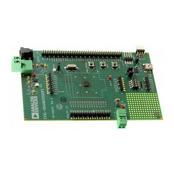
Analog Devices ADuCM320 Hardware Reference Manual (196 pages)
Brand:
Analog Devices
| Category:
Motherboard
| Size: 2 MB
Table of Contents
1/2015-Rev. 0 to Rev. a Changes to Figure
1
Disclaimer
1
Functional Block Diagram
1
Scope
1
Table of Contents
2
Revision History
4
Changes to Register Access Conventions Section
6
Using the Aducm320 Hardware Reference Manual
6
Number Notations
6
Register Access Conventions
6
Acronyms and Abbreviations
6
Changes to Introduction to the Aducm320 Section
7
Memory Organization
8
Introduction to the Aducm320
7
Main Features of Aducm320
7
Clocking Architecture
10
Clocking Architecture Features
10
Clocking Architecture Block Diagram
11
Clocking Architecture Overview
12
Register Summary: Clock Architecture
12
Clocking Architecture Operation
12
1 /2017-Rev. B to Rev. C
12
Changes to Clocking Architecture Operation Section
12
Changes to Table 4 and Clocking Architecture Operation Section
12
Change to Table 5
13
Register Details: Clock Architecture
13
Moved Register Summary: Clock Architecture Section
12
2/2016-Rev. a to Rev. B Changes to Table 7
14
Changes to Table 6 and Table 7
14
Added Clocking Status Register Section and Table 8; Renumbered Sequentially
15
Power Management Unit
16
Power Management Unit Features
16
Power Management Unit Overview
16
Power Management Unit Operation
16
Code Examples
17
Register Summary: Power Management Unit
18
Register Details: Power Management Unit
18
ARM Cortex-M3 Processor
19
ARM Cortex-M3 Processor Features
19
ARM Cortex-M3 Processor Overview
19
ARM Cortex-M3 Processor Operation
19
Changes to Debug Support Section
19
ARM Cortex-M3 Processor Related Documents
20
ADC Circuit
21
ADC Circuit Features
21
ADC Circuit Block Diagram
21
Changes to ADC Circuit Features Section
21
ADC Circuit Overview
22
ADC Circuit Operation
22
Changes to ADC Circuit Overview Section
22
ADC Transfer Function
23
Changes to Single-Ended Mode Section and Differential Section
23
ADC Typical Setup Sequence
24
ADC Input Buffer
24
ADC Internal Channels
24
ADC Support Circuits
25
Changes to ADC Voltage Reference Selection Section
26
Added Figure 8; Renumbered Sequentially
27
Changes to Table 12
28
Register Summary: ADC Circuit
28
Register Details: ADC Circuit
29
Change to Table 14
30
Changes to Table 16
31
Changes to Table 17
32
Changes to Table 22
33
Register Details: Additional Registers
33
Register Summary: Additional Registers
33
Changes to Table 23
34
Analog Comparator
35
Analog Comparator Features
35
Analog Comparator Overview
35
Analog Comparator Operation
35
Register Summary: Analog Comparator
36
Register Details: Analog Comparator
36
Changes to Table 25
36
Idacs
37
IDAC Features
37
IDAC Block Diagram
37
IDAC Overview
37
Changes to Case 2-Turn on IDAC2 but to Set the Output to 0 Ma with the Lowest Possible Offset Section
38
Added IDAC Thermal Shutdown Section
39
Register Summary: IDAC
40
Register Details: IDAC
40
Vdacs
43
VDAC Features
43
VDAC Block Diagram
43
VDAC Overview
43
VDAC Operation
43
Register Summary: VDAC
44
Register Details: VDAC
44
System Exceptions and Peripheral Interrupts
49
Cortex-M3 and Fault Management
49
External Interrupt Configuration
53
Register Summary: External Interrupts
53
Register Details: External Interrupts
53
Low Voltage Analog die Interrupt Configuration
56
Register Summary: Low Voltage die Interrupts
57
Register Details: Low Voltage die Interrupts
57
Reset
59
Reset Features
59
Reset Operation
59
Register Summary: Reset
60
Register Details: Reset
60
DMA Controller
61
DMA Features
61
DMA Overview
61
DMA Operation
61
DMA Interrupts
61
DMA Priority
62
Channel Control Data Structure
62
Changes to Table 74
62
Control Data Configuration
63
DMA Transfer Types (CHNL_CFG[2:0])
64
Changes to Table 75
64
Changes to Table 76
65
Added Aborting DMA Transfers Section
65
Address Calculation
66
Aborting DMA Transfers
66
Register Summary: DMA
67
Register Details: DMA
67
Changes to Protection, Integrity Section
72
Changed Top of Flash Blocks Section to Reserved Flash Locations Section
73
Flash Memory Operation
74
Flash Controller
73
Flash Controller Features
73
Flash Controller Overview
73
Flash Controller Operation
73
Changes to Erasing Flash Section and Signature Section
74
Changes to Writing to Flash Section
75
Added ECC Error Handling Section, ECC Error During Read Section, and ECC Error During Execution of Sign Command Section
76
Changes to CPU Execution Speed Section
76
Changes to Memory Cache Section
77
Flash Protection
78
Changes to Table 95 and Table 96
79
Changes to Table 95 and Table 96
80
Register Summary: Flash Controller
82
Register Details: Flash Controller
82
Added Table 112
84
Changes to Cache Status Register Section
84
Added Table 113 and Table 114
85
Changes to Cache Setup Register Section and Cache Key Register Section
85
Deleted Shared MDIO Pins Section
85
Added ECC Enable/Disable, Error Response Register Section, Flash 0 ECC Error Address Register Section, Flash 1 ECC Error Address Register Section, and Table 112 to Table 114; Renumbered Sequentially
86
Added Inaccessible Bits Section
86
Changes to Digital I/Os Features Section and Digital I/Os Overview Section
86
Changes to I/O Pull-Up Enable (Gpxpul) Section
87
Changes to Open-Drain Enable (Gpxode) Section
88
Silicon Identification
90
Silicon Identification Memory Mapped Registers
90
Digital die ID Register
90
Low Voltage die ID Register
90
Digital I/Os
91
Digital I/Os Features
91
Digital I/Os Block Diagram
91
Digital I/Os Overview
91
Digital I/Os Operation
91
Digital Port Multiplex
94
Changes to Table 121
94
Register Summary: Digital I/O
96
Register Details: Digital I/O
97
I 2 C Serial Interface
101
I 2 C Features
101
I 2 C Overview
101
I 2 C Operation
101
I 2 C Operating Modes
103
Register Summary: I2C0
105
Register Details: I2C0
105
Register Summary: I2C1
114
Register Details: I2C1
114
Serial Peripheral Interfaces
123
SPI Features
123
SPI Overview
123
SPI Operation
123
SPI Transfer Initiation
124
SPI Interrupts
126
Spi Wire-Or'ed Mode (Wom)
127
SPI CSERR Condition
127
Spi Dma
127
SPI and Power-Down Modes
128
Register Summary: SPI0
128
Register Details: SPI0
128
Changes to Table 182
130
Register Summary: SPI1
132
Register Details: SPI1
132
UART Serial Interface
137
UART Features
137
UART Overview
137
UART Operation
137
Register Summary: UART
141
Register Details: UART
141
Pla
146
PLA Features
146
PLA Overview
146
PLA Operation
147
Register Summary: PLA
150
Register Details: PLA
150
General-Purpose Timers
154
General-Purpose Timers Features
154
General-Purpose Timers Block Diagram
154
General-Purpose Timers Overview
154
General-Purpose Timers Operation
155
Register Summary: General-Purpose Timer 0
157
Register Details: General-Purpose Timer 0
157
Register Summary: General-Purpose Timer 1
160
Register Details: General-Purpose Timer 1
160
Register Summary: General-Purpose Timer 2
163
Register Details: General-Purpose Timer 2
163
Watchdog Timer
166
Watchdog Timer Features
166
Watchdog Timer Block Diagram
166
Watchdog Timer Overview
166
Watchdog Timer Operation
166
Register Summary: Watchdog Timer
167
Register Details: Watchdog Timer
167
Wake-Up Timer
169
Wake-Up Timer Features
169
Wake-Up Timer Block Diagram
169
Wake-Up Timer Overview
169
Wake-Up Timer Operation
169
Register Summary: Wake-Up Timer
172
Register Details: Wake-Up Timer
172
Pwm
176
PWM Features
176
PWM Overview
176
PWM Operation
176
PWM Interrupt Generation
179
Register Summary: PWM
180
Register Details: PWM
180
Added MDIO Interrupt Power-Up Register Write Sequence Section
184
Mdio
184
MDIO Features
184
MDIO Overview
184
MDIO Operation
184
Block Switching
186
Register Summary: MDIO Interface (MDIO)
191
Register Details: MDIO
191
Hardware Design Considerations
194
Typical System Configuration
194
Rev. C
196
Serial Wire Debug Interface
196
Advertisement
Advertisement
Related Products
Analog Devices ADuCM350
Analog Devices ADuCM310
Analog Devices ADUCM310BBCZ
Analog Devices ADUCM310BBCZ-RL
Analog Devices ADuCM362
Analog Devices ADuCM363
Analog Devices ADUC816
Analog Devices ADUC834
Analog Devices ADUC845
Analog Devices MICROCONVERTER ADUC814-28TSSOP
Analog Devices Categories
Motherboard
Computer Hardware
Controller
Media Converter
Extender
More Analog Devices Manuals
Login
Sign In
OR
Sign in with Facebook
Sign in with Google
Upload manual
Upload from disk
Upload from URL