Sign In
Upload
Manuals
Brands
Ametek Manuals
Power Supply
ASTDC60D1C-E00
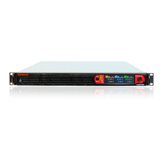
Ametek ASTDC60D1C-E00 Manuals
Manuals and User Guides for Ametek ASTDC60D1C-E00. We have
1
Ametek ASTDC60D1C-E00 manual available for free PDF download: Programming Manual
Ametek ASTDC60D1C-E00 Programming Manual (151 pages)
RS232, USB, Ethernet and IEEE 488.2
Brand:
Ametek
| Category:
Power Supply
| Size: 1.82 MB
Table of Contents
Table of Contents
8
1 Overview
17
Introduction
17
RS232 Interface
17
USB Interface
18
Ethernet Interface
18
IEEE 488.2 GPIB Interface
18
2 Features, Functions and Specifications
19
Introduction
19
Features of RS232 Interface
19
Features of USB Interface
19
Features of Ethernet Interface
20
Features of IEEE 488.2 GPIB Interface
20
Programmable Functions
20
Readback Functions
21
Specifications
21
Programming Resolution
21
Programming Accuracy
21
Readback Resolution
22
Readback Accuracy
22
Minimum System Requirements
22
PC Connection
22
Internet or LAN Connection
22
3 Remote/Local Selection
23
Introduction
23
Remote Mode
23
Figure 3-1. Local/Remote Screen
23
Figure 3-2. Dashboard Screen
23
Local Lock out Mode
24
Figure 3-3. Local Lockout Screen
24
Figure 3-4. Home-Screen
24
4 Rs232 Configurations and Remote Programming
27
Rear Panel
27
Remote Programming Via RS232
27
RS232 Connector Pinout
27
Figure 4-1. Rear Panel - RS232 Interface
27
Table 4-1. RS-232C Interface Connector Type
28
Table 4-2. RS-232C Interface Connector Pinout
28
Figure 4-2. RS-232C Interface Connector
28
RS232 Setup Procedure
29
Table 4-3. RS-232C Interface Connector Pinout
29
Figure 4-3. RS232 Communications Cable Pinout
30
Figure 4-4. RS232 Screen (Configure)
30
Figure 4-5. Port Setting in Tera Term
31
Figure 4-6. Baud Rate Setting in Tera Term
31
Figure 4-7. Terminal Option in Tera Term
32
Figure 4-8. Terminal Setup in Tera Term
32
5 Usb Configurations and Remote Programming
35
Rear Panel
35
Usb Setup Procedure
36
Port Number Identification
36
Communication Test Using Serial Interface Program
37
6 Ethernet Configuration and Remote Programming
40
Introduction
40
Ethernet/Lan Configuration
40
Ethernet Configuration Factory Defaults
41
Rear Panel
41
Figure 6-1. Rear Panel - Ethernet Interface
41
Ethernet Setup Procedure
42
Network Setup Using DHCP Server
42
Figure 6-2. LAN Screen (Configure)
42
Figure 6-3. LAN Screen
42
Figure 6-4. LAN Screen (Settings)
43
Network Setup Using Auto-IP (Direct Connection between Asterion Power Supply and PC Using Cross Cable)
44
Figure 6-5. RS232 Screen (Settings)
44
Network Setup Using Static IP
45
Figure 6-6. LAN Configure (Settings)
45
Figure 6-7. LAN Screen (Configure Static IP)
45
Raw Socket Interface
46
Protocol
46
Web Server
47
Ethernet Web Pages, Overview
47
Figure 6-8. Asterion DC Power Supply Banner and Tab
47
Figure 6-9. Login Window
47
Figure 6-10. Asterion DC Power Supply Home Page
48
Home
48
Figure 6-11. Asterion DC Power Supply Device Identify
49
Figure 6-12. Asterion DC Power Supply IP Configuration Page
49
IP Configuration
49
Figure 6-13. Interactive Control Page
51
Interactive Control
51
Figure 6-14. LXI Identification Page
52
LXI Identification
52
7 Ieee 488.2 Gpib Configurations and Remote
54
Programming
54
Rear Panel
54
Figure 7-1. Rear Panel - IEEE 488.2 GPIB Interface
54
Remote Programming Via IEEE488.2 GPIB Connector
55
Address Selection
55
Power-On GPIB Service Request (PON SRQ) Selection
55
Shield Ground
55
IEEE 488.2 GPIB Setup Procedure
55
Figure 7-2. GPIB Screen
55
8 Remote Analog Programming and External User
57
Control Interface Connector
57
Introduction
57
REMOTE Analog Programming Connector Details
57
Figure 8-1. Rear Panel - Analog Programming Connector
57
Figure 8-2 Remote Analog Programming and External User Control Interface Connector Pin-Out
58
Table 8-1. Analog Programming Connector, Designations and Functions
65
Remote ANALOG Programming
66
Remote Programming by Resistance
66
Figure 8-3 Remote Current Programming Using Resistance
67
Figure 8-4 Remote Voltage Programming Using Resistance
68
Figure 8-5 Remote Power Programming Using Resistance
68
Remote Programming by VOLTAGE
69
Figure 8-6 Remote Current Programming Using 0-5 VDC or 0-10 VDC Source
69
Figure 8-7 Remote Voltage Programming Using 0-10 VDC Source
70
Remote Programming by 4-20Ma SOURCE
71
Figure 8-8 Remote Power Programming Using 0-10 VDC Source
71
Figure 8-9 Remote Current Programming Using 4-20Ma Source
72
Remote Overvoltage Programming
73
Remote MONITOR OUTPUTS
74
Remote Digital Input and Output
74
Auxiliary Power Output
74
Digital Outputs
75
Figure 8-13 External Isolation and Polarity Relay Interface to Control Interface
76
Digital Inputs
77
Fault
77
Trigger-In & Trigger out
80
Remote Output On/Off Control
80
Remote Output ON/OFF by Contact Closure
80
Table 8-2. List of Faults in DC-Asterion Power Supply
80
Remote Output ON/OFF Control by External Source
81
9 Rs232/Ethernet/ Ieee 488.2 Gpib and Scpi Command
83
Operation
83
Introduction
83
Register Definitions
83
Protection Condition and Protection Event Status Register
83
Table 9-1. Protection Condition and Event Status Registers
85
Standard Event Status Register (ESR)
86
Table 9-2. Standard Event Status Register
86
SCPI Status Byte
87
Table 9-3. SCPI Status Byte
88
Error/Event Queue
89
Table 9-4 SCPI Error Codes
89
Serial Poll Operation
90
SCPI Conformance Information
91
Parameter Definitions
91
Conventions
91
Queries
92
IEEE 488.2 Common Command Subsystem
92
SOURCE SCPI Command Subsystem
94
SOURCE SCPI Command Summary
94
SOURCE SCPI Command Reference
97
Ramp Function
102
MEASURE SCPI Command Subsystem
103
MEASURE SCPI Command Summary
103
MEASURE SCPI Command Reference
103
OUTPUT SCPI Command Subsystem
104
OUTPUT SCPI Command Summary
104
OUTPUT SCPI Command Reference
105
SYSTEM SCPI Command Subsystem
106
SYSTEM SCPI Command Summary
106
SYSTEM SCPI Command Reference
107
HTRIGGER SCPI Command Subsystem
109
HTRIGGER SCPI Command Summary
109
HTRIGGER SCPI Command Reference
109
TRIGGER SCPI Command Subsystem
109
TRIGGER SCPI Command Summary
109
TRIGGER SCPI Command Reference
109
CALIBRATION SCPI Command Subsystem
110
CALIBRATION SCPI Command Summary
110
CALIBRATION SCPI Command Reference
113
STATUS SCPI Command Subsystem
120
STATUS SCPI Command Summary
120
STATUS SCPI Command Reference
120
Examples of Using the SCPI Commands
120
VI Mode Example
120
OVP Setup Example
121
Trigger Example
122
Ramp I Example
122
Ramp V Example 2
123
Power on INIT Example
123
10 Calibration
124
Introduction
124
Setup for Calibration
125
Voltage Programming Calibration
125
Voltage Programming Calibration - REMOTE SENSE
128
Current Programming Calibration
130
Analog Program Adjustment
132
Voltage Programming - 10V Range Voltage Source Calibration
133
Voltage Programming - 5V Range Voltage Source Calibration
133
Voltage Programming - Current Source (Resistance Programming) Calibration
134
Voltage Programming - 4-20Ma Source Calibration
135
Current Programming - 10V Range Voltage Source Calibration
135
Current Programming - 5V Range Voltage Source Calibration
136
Current Programming - Current Source (Resistance Programming) Calibration
137
CURRENT Programming - 4-20Ma Source Calibration
137
Power Programming - 10V Range Voltage Source Calibration
138
POWER Programming - 5V Range Voltage Source Calibration
139
POWER Programming - Current Source (Resistance Programming) Calibration
139
POWER Programming - 4-20Ma Source Calibration
140
OVER-Voltage Programming - 10V Range Calibration
141
OVER-Voltage Programming - 5V Range Calibration
141
11 Scpi Status Implementation
145
SCPI Status Byte Implementation
145
Figure 11-1. SCPI Status Implementation Diagram
146
Advertisement
Advertisement
Related Products
Ametek AMREL SPS-A Series
Ametek ASTDC125D1C-E00
Ametek LAND APS42
Ametek AMREL SPS Series
Ametek Jofra ASC-400
Ametek JOFRA ASC321
Ametek JOFRA ASM-803 A
Ametek JOFRA ASM-803 B
Ametek JOFRA ASM-802
Ametek Jofra ASM-802 B
Ametek Categories
Measuring Instruments
Test Equipment
Power Supply
Controller
Laboratory Equipment
More Ametek Manuals
Login
Sign In
OR
Sign in with Facebook
Sign in with Google
Upload manual
Upload from disk
Upload from URL