Ruckus Wireless ZoneFlex 7055 User Manual
Indoor access point
Hide thumbs
Also See for ZoneFlex 7055:
- User manual (187 pages) ,
- Quick setup manual (2 pages) ,
- Quick setup manual (2 pages)
Table of Contents
Advertisement
Ruckus Wireless
TM
Indoor Access Point
Release 100.2.0 User Guide
For the following indoor Ruckus Wireless AP models:
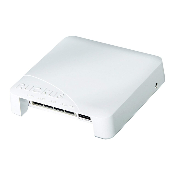
- ZoneFlex 7055 Dual-Band 802.11n Wired/Wireless Wi-Fi Wall Switch
- ZoneFlex 7321 2.4/5GHz 802.11n Smart Wi-Fi Access Point
- ZoneFlex 7341 Single-Band 802.11n Access Point
- ZoneFlex 7343 Single-Band 802.11n Access Point
- ZoneFlex 7352 802.11n Smart Wi-Fi Access Point
- ZoneFlex 7363 Dual-Band 802.11n Smart Wi-Fi Access Point
- ZoneFlex 7372 and 7372-E Dual-Band 802.11n Smart Wi-Fi Access Point
- ZoneFlex 7441 802.11n DAS Access Point
- ZoneFlex 7982 Dual-Band 802.11n Smart Wi-Fi Access Point
- ZoneFlex H500 Dual-Band 802.11ac Multimedia Wi-Fi Access Point Wall Switch
- ZoneFlex R300 Dual-Band 802.11n Smart Wi-Fi Access Point
- ZoneFlex R500 Dual-Band 802.11ac Smart Wi-Fi Access Point
- ZoneFlex R600 Dual-Band 802.11ac Smart Wi-Fi Access Point
- ZoneFlex R700 Dual-Band 802.11ac Smart Wi-Fi Access Point
- ZoneFlex R710 Dual-Band 802.11ac Smart Wi-Fi Access Point
Part Number 800-70892-001 Rev B
Published 25 June, 2015
www.ruckuswireless.com
Advertisement
Table of Contents

Related Manuals for Ruckus Wireless ZoneFlex 7055


Summary of Contents for Ruckus Wireless ZoneFlex 7055
- Page 1 Indoor Access Point Release 100.2.0 User Guide For the following indoor Ruckus Wireless AP models: - ZoneFlex 7055 Dual-Band 802.11n Wired/Wireless Wi-Fi Wall Switch - ZoneFlex 7321 2.4/5GHz 802.11n Smart Wi-Fi Access Point - ZoneFlex 7341 Single-Band 802.11n Access Point - ZoneFlex 7343 Single-Band 802.11n Access Point...
-
Page 2: Limitation Of Liability
Dynamic PSK, FlexMaster, MediaFlex, MetroFlex, Simply Better Wireless, SmartCast, SmartMesh, SmartSec, Speed- Flex, ZoneDirector, ZoneSwitch, and ZonePlanner are trademarks of Ruckus Wireless, Inc. in the United States and other countries. All other product or company names may be trademarks of their respective owners. -
Page 3: Table Of Contents
Overview of the Ruckus Wireless AP........ - Page 4 Configuring Wireless Settings ..........126 Ruckus Wireless Indoor AP 100.2.0 User Guide, 800-70892-001 Rev A...
- Page 5 Enabling Logging and Sending Event Logs to a Syslog Server ....173 Sending a Copy of the Log File to Ruckus Wireless Support ....174 Saving a Copy of the Current Log to Your Computer .
- Page 6 Index Ruckus Wireless Indoor AP 100.2.0 User Guide, 800-70892-001 Rev A...
-
Page 7: About This Guide
Most user guides and release notes are available in Adobe Acrobat Reader Portable Document Format (PDF) or HTML on the Ruckus Wireless Support Web site at https://support.ruckuswireless.com/documents Continue with the following: •... -
Page 8: Safety Warnings
CAUTION! This product and all interconnected equipment must be installed indoors within the same building, including the associated LAN connections as defined by Environment A of the IEEE 802.af Standard. Ruckus Wireless Indoor AP 100.2.0 User Guide, 800-70892-001 Rev A... -
Page 9: Related Documentation
About This Guide Related Documentation Related Documentation In addition to this User Guide, each Ruckus Wireless AP documentation set includes the following: • Installation Guide/Getting Started Guide/Mounting Guide: Provides essential installation and configuration information to help you get the AP up and running within minutes. -
Page 10: Document Conventions
Information that describes important features or instructions. CAUTION! Information that alerts you to potential loss of data or potential damage to an application, system, or device. WARNING! Information that alerts you to potential personal injury. Ruckus Wireless Indoor AP 100.2.0 User Guide, 800-70892-001 Rev A... -
Page 11: Introducing The Ruckus Wireless Ap
Introducing the Ruckus Wireless AP In this chapter: • Overview of the Ruckus Wireless AP • Unpacking the Ruckus Wireless AP • Getting to Know the AP Features Ruckus Wireless Indoor AP 100.2.0 User Guide, 800-70892-001 Rev A... -
Page 12: Overview Of The Ruckus Wireless Ap
FlexMaster (FM) manager, or as part of the Ruckus Wireless Smart WLAN system, in which it can be managed by a Ruckus Wireless controller. The rest of this document collectively refers to the SCG, vSCG SZ, vSZ, ZD, SAMs and other controllers as Ruckus Wireless controllers. -
Page 13: Unpacking The Ruckus Wireless Ap
• Declaration of Conformity, if required • Quick Setup Guide • (Ethernet cables, power adapters and mounting kits are optional accessories that may or may not be included depending on the SKU purchased) Ruckus Wireless Indoor AP 100.2.0 User Guide, 800-70892-001 Rev A... -
Page 14: Getting To Know The Ap Features
Getting to Know the AP Features Getting to Know the AP Features This section identifies the physical features of each Ruckus Wireless AP model that is discussed in this guide. Before you begin the installation process, Ruckus Wireless recommends that you become familiar with these features. -
Page 15: Zoneflex 7055 Dual-Band Wired/Wireless Wall Switch
Introducing the Ruckus Wireless AP Getting to Know the AP Features ZoneFlex 7055 Dual-Band Wired/Wireless Wall Switch The ZoneFlex 7055 is a multiservice 802.11n dual-band concurrent two-stream wired/wireless wall switch. NOTE The 100.x AP base images support standalone mode and FlexMaster (FM) WLAN manager operation. - Page 16 PoE In LAN/Uplink Uplink LAN port that supports 802.3af and 802.3at Power over Ethernet (PoE) input. Punch down Block 110 punchdown block. Pass Through Port RJ-45 pass through port for the pass through connection. Ruckus Wireless Indoor AP 100.2.0 User Guide, 800-70892-001 Rev A...
-
Page 17: Leds
Amber: The WLAN is up, but no clients are associated and no downlink MAPs are connected. Green: The WLAN is up and at least one client is associated. No downlink MAPs are connected. Ruckus Wireless Indoor AP 100.2.0 User Guide, 800-70892-001 Rev A... -
Page 18: Reset Buttons
Press and release the Hard Reset button to restart the AP. NOTE On the 7055, the Hard reset button restarts the AP, while the Soft reset button reverts the AP to factory default settings. Ruckus Wireless Indoor AP 100.2.0 User Guide, 800-70892-001 Rev A... -
Page 19: Zoneflex 7321 Ap
7321. For a description of front panel elements, refer to Table Figure 4. 7321 front panel Table 6. 7321 front panel elements Description PWR LED • Off: Off. • Red: Boot up in process. • Green: On. Ruckus Wireless Indoor AP 100.2.0 User Guide, 800-70892-001 Rev A... - Page 20 MAP is connected. No clients are associated. • Fast flashing green (two flashes every second): The WLAN is up, at least one downlink MAP is connected, and at least one client is associated. Ruckus Wireless Indoor AP 100.2.0 User Guide, 800-70892-001 Rev A...
-
Page 21: Rear Panel
MAP is connected, and at least one client is associated. Rear Panel Figure 5 shows the bottom view of the 7321. For a description of each rear panel part, refer to Table Figure 5. 7321 rear panel Ruckus Wireless Indoor AP 100.2.0 User Guide, 800-70892-001 Rev A... -
Page 22: Zoneflex 7341 Ap
ZD controllers. The 7341 requires a minimum of AP base image 100.0.0 and later to operate, or Ruckus Wireless controllers 1.0 and later, vSZ 2.5 and later, or ZD 9.0 and later to operate. ZoneFlex 7341 includes five LEDs on its front panel and buttons and connectors on its rear panel. - Page 23 AP is still searching for a mesh uplink. Fast flashing green (two flashes every second): The AP is • fair . functioning as a MAP and the wireless signal to its uplink AP is Ruckus Wireless Indoor AP 100.2.0 User Guide, 800-70892-001 Rev A...
- Page 24 One RJ-45 port for a 10/100/1000 PoE (Power over Port Ethernet, 802.3af) connection. Power Connect the power adapter (12 VDC/1.25A) to this socket. Power can also be supplied via the 10/100/ 1000 PoE (802.3af) port. Ruckus Wireless Indoor AP 100.2.0 User Guide, 800-70892-001 Rev A...
-
Page 25: Zoneflex 7343 Ap
The 100.x AP base images support standalone mode and FlexMaster (FM) WLAN manager operation. The SmartZone software-compatible images only support Ruckus Wireless SCG, SZ and vSZ controllers. The ZD-compatible images only support ZD controllers. The 7343 requires a minimum of AP base image 100.0.0 and later to operate, or SCG 1.0 and later, vSZ 2.5 and later, or ZD 9.0 and later to operate. - Page 26 AP is still searching for a mesh uplink. Fast flashing green (two flashes every second): The AP is • fair . functioning as a MAP and the wireless signal to its uplink AP is Ruckus Wireless Indoor AP 100.2.0 User Guide, 800-70892-001 Rev A...
- Page 27 One RJ-45 port for a 10/100/1000 PoE (Power over Port Ethernet, 802.3af) connection. Power Connect the power adapter (12 VDC/1.25A) to this socket. Power can also be supplied via the 10/100/ 1000 PoE (802.3af) port. Ruckus Wireless Indoor AP 100.2.0 User Guide, 800-70892-001 Rev A...
-
Page 28: Zoneflex 7352 Ap
The 100.x AP base images support standalone mode and FlexMaster (FM) WLAN manager operation. The SmartZone software-compatible images only support Ruckus Wireless SCG, SZ and vSZ controllers The ZD-compatible images only support ZD controllers. The 7352 requires a minimum of AP base image 100.0.0 and later to operate, or SCG 1.1.1 and later, vSZ 2.5 and later, SmartZone software 3.2 and later, or ZD... - Page 29 AP is still searching for a mesh uplink. • Fast flashing green (two flashes every second): The AP is functioning as a MAP and the wireless signal to its uplink AP is fair . Ruckus Wireless Indoor AP 100.2.0 User Guide, 800-70892-001 Rev A...
- Page 30 AP. Pressing and holding it for six seconds resets the AP to factory default settings. Resetting the AP to factory default CAUTION! settings erases all previously configured settings. Ruckus Wireless Indoor AP 100.2.0 User Guide, 800-70892-001 Rev A...
-
Page 31: Zoneflex 7363 Ap
ZD controllers. The 7363 requires a minimum of AP base image 100.0.0 and later to operate, or Ruckus Wireless controllers 1.0 and later, vSZ 2.5 and later, or ZD 9.0 and later to operate. The 7363 includes five LEDs on its front panel, and buttons and connectors on its rear panel. - Page 32 • Amber: The WLAN service is up, at least one wireless client is associated (standalone), or at least one downlink MAP is connected (RAP), or uplink RAP is connected (MAP), but signal quality is poor (RSSI < 15). Ruckus Wireless Indoor AP 100.2.0 User Guide, 800-70892-001 Rev A...
- Page 33 One RJ-45 port for a 10/100/1000 PoE (Power over Port Ethernet, 802.3af) connection. Power Connect the power adapter (12 VDC/1.25A) to this socket. Power can also be supplied via the 10/100/ 1000 PoE (802.3af) port. Ruckus Wireless Indoor AP 100.2.0 User Guide, 800-70892-001 Rev A...
-
Page 34: Zoneflex 7372 Ap
The 7372 includes five LEDs on its front panel and buttons and connectors on its rear panel. Front Panel Figure 14 shows the top view of the 7372. For a description of each front panel part, refer to Table Figure 14. 7372 top view Ruckus Wireless Indoor AP 100.2.0 User Guide, 800-70892-001 Rev A... - Page 35 • Off: The WLAN service is down. • Green: The WLAN is up and at least one client is associated. • Amber: The WLAN is up. No clients are associated. Ruckus Wireless Indoor AP 100.2.0 User Guide, 800-70892-001 Rev A...
- Page 36 MAP is connected, and at least one client is associated. Rear Panel The rear panel of the 7372 is the same as the 7352. See Figure Ruckus Wireless Indoor AP 100.2.0 User Guide, 800-70892-001 Rev A...
-
Page 37: Zoneflex 7372-E Ap
The 7372-E includes five LEDs on its front panel and buttons and connectors on its rear panel. Front Panel Figure 14 shows the top view of the 7372-E. For a description of each front panel part, refer to Table Figure 15. 7372-E top view Ruckus Wireless Indoor AP 100.2.0 User Guide, 800-70892-001 Rev A... - Page 38 • Off: The WLAN service is down. • Green: The WLAN is up and at least one client is associated. • Amber: The WLAN is up. No clients are associated. Ruckus Wireless Indoor AP 100.2.0 User Guide, 800-70892-001 Rev A...
- Page 39 MAP is connected, and at least one client is associated. Rear Panel Figure 16 shows the rear panel of the 7372-E. For a description of each rear panel part, refer to Table Figure 16. 7372-E rear panel Ruckus Wireless Indoor AP 100.2.0 User Guide, 800-70892-001 Rev A...
- Page 40 Connect the power adapter (12 VDC/1.25A) to this socket. Power can also be supplied via the 10/100/ 1000 PoE port. 5 (two RP-SMA Connect to dual-band 2.4GHz and 5GHz external places) connectors antennas. Ruckus Wireless Indoor AP 100.2.0 User Guide, 800-70892-001 Rev A...
-
Page 41: Zoneflex 7441 Das Ap
Attach the ground wire using the included terminal ring and hex nuts. Power socket DC power socket. Reset button Resets the AP to factory default settings if held for more than 5 seconds. Ruckus Wireless Indoor AP 100.2.0 User Guide, 800-70892-001 Rev A... - Page 42 • Flashing green: The WLAN service is up and no clients are associated. AIR LED • Not used at this time. Cable antenna • Type N female coaxial cable connector for in-building DAS connector wireless systems. Ruckus Wireless Indoor AP 100.2.0 User Guide, 800-70892-001 Rev A...
-
Page 43: Zoneflex 7982 Ap
The 7982 includes five LEDs on its front panel and buttons and connectors on its rear panel. Front Panel Figure 18 shows the top view of the 7982. For a description of each front panel part, refer to Table Figure 18. 7982 top view Ruckus Wireless Indoor AP 100.2.0 User Guide, 800-70892-001 Rev A... - Page 44 • Off: The WLAN service is down. • Green: The WLAN is up and at least one client is associated. • Amber: The WLAN is up. No clients are associated. Ruckus Wireless Indoor AP 100.2.0 User Guide, 800-70892-001 Rev A...
- Page 45 MAP is connected, and at least one client is associated. Rear Panel Figure 19 shows the rear panel of the 7982. For a description of each rear panel part, refer to Table Figure 19. 7982 rear panel Ruckus Wireless Indoor AP 100.2.0 User Guide, 800-70892-001 Rev A...
- Page 46 For units with Power over Ethernet (PoE). These products and all interconnected equipment must be installed indoors within the same building, including the associated LAN connections, as defined by Environment A of the IEEE 802.3af Standard. Ruckus Wireless Indoor AP 100.2.0 User Guide, 800-70892-001 Rev A...
-
Page 47: Zoneflex H500 Ap Wall Switch
• The USB port is intended for low-power devices such as BLE beacons. The maximum power that the USB port can supply is 0.5W. • The LAN1+PoE port is intended for PoE-powered peripheral devices such as IP telephones. Ruckus Wireless Indoor AP 100.2.0 User Guide, 800-70892-001 Rev A... -
Page 48: Front Panel
DC power adapter (sold separately) 12.95W PoE Out (802.3af Class 3) and 0.5W USB Front Panel Figure 20 shows the front view of the H500. Figure 20. H500 front view Ruckus Wireless Indoor AP 100.2.0 User Guide, 800-70892-001 Rev A... - Page 49 H500. For a description of each rear panel part, refer to Table Figure 21. H500 rear view Table 23. H500 rear panel elements Description • Off: Off. • Red: Boot up in process. • Green: On. Ruckus Wireless Indoor AP 100.2.0 User Guide, 800-70892-001 Rev A...
- Page 50 Getting to Know the AP Features Table 23. H500 rear panel elements (Continued) Description • Off: The AP is not being managed by a Ruckus Wireless controller (standalone mode). • Green: The AP is being managed by a Ruckus Wireless controller.
-
Page 51: Bottom Panel
LAN1+PoE port 10/100 RJ-45 LAN port with PoE out. Supports 802.3af PSE About Class 2 or 3 (depending on power input; refer to Peripheral Devices 48VDC port Optional 48VDC power input connector. Ruckus Wireless Indoor AP 100.2.0 User Guide, 800-70892-001 Rev A... - Page 52 AP. This is the same as removing power and then and restoring power to the H500. CAUTION! Resetting the AP to factory default settings erases all previously configured settings. Ruckus Wireless Indoor AP 100.2.0 User Guide, 800-70892-001 Rev A...
-
Page 53: Zoneflex R300 Ap
Smart Mesh or Spectrum Analysis features, and supports a maximum of 250 unencrypted clients. Front Panel Figure 24 shows the top view of the R300. For a description of each front panel part, refer to Table Figure 24. R300 top view Ruckus Wireless Indoor AP 100.2.0 User Guide, 800-70892-001 Rev A... - Page 54 • Off: The WLAN service is down. • Green: The WLAN service is up and at least one client is associated. Amber: The WLAN service is up and no clients are associated. • Ruckus Wireless Indoor AP 100.2.0 User Guide, 800-70892-001 Rev A...
- Page 55 Resetting the AP to factory default settings CAUTION! erases all previously configured settings. Power Connect the power adapter (12 VDC/1.25A) to this socket. Power can also be supplied via the 10/100/1000 PoE port. Ruckus Wireless Indoor AP 100.2.0 User Guide, 800-70892-001 Rev A...
-
Page 56: Zoneflex R500 Ap
The R500 includes five LEDs on its front panel and buttons and connectors on its rear panel. Front Panel Figure 26 shows the top view of the R500. For a description of the front panel LEDs, refer to Table Figure 26. R500 top view Ruckus Wireless Indoor AP 100.2.0 User Guide, 800-70892-001 Rev A... - Page 57 • Off: The WLAN service is down. • Green: The WLAN is up and at least one client is associated. • Amber: The WLAN is up. No clients are associated. Ruckus Wireless Indoor AP 100.2.0 User Guide, 800-70892-001 Rev A...
- Page 58 MAP is connected. No clients are associated. • Fast flashing green (two flashes every second): The WLAN is up, at least one downlink MAP is connected, and at least one client is associated. Ruckus Wireless Indoor AP 100.2.0 User Guide, 800-70892-001 Rev A...
- Page 59 PoE Port One RJ-45 port for a 10/100/1000 PoE (Power over Ethernet, 802.3af/at) connection. (The R500 is a Class 3 device.) Ethernet One RJ-45 port for a 10/100/1000 connection. Port Ruckus Wireless Indoor AP 100.2.0 User Guide, 800-70892-001 Rev A...
- Page 60 For units using Power over Ethernet (PoE). These products and all interconnected equipment must be installed indoors within the same building, including the associated LAN connections, as defined by Environment A of the IEEE 802.3af Standard. Ruckus Wireless Indoor AP 100.2.0 User Guide, 800-70892-001 Rev A...
-
Page 61: Zoneflex R600 Ap
The R600 includes five LEDs on its front panel and buttons and connectors on its rear panel. Front Panel Figure 28 shows the top view of the R600. For a description of the front panel LEDs, refer to Table Figure 28. R600 top view Ruckus Wireless Indoor AP 100.2.0 User Guide, 800-70892-001 Rev A... - Page 62 • Off: The WLAN service is down. • Green: The WLAN is up and at least one client is associated. • Amber: The WLAN is up. No clients are associated. Ruckus Wireless Indoor AP 100.2.0 User Guide, 800-70892-001 Rev A...
- Page 63 MAP is connected. No clients are associated. • Fast flashing green (two flashes every second): The WLAN is up, at least one downlink MAP is connected, and at least one client is associated. Ruckus Wireless Indoor AP 100.2.0 User Guide, 800-70892-001 Rev A...
- Page 64 PoE Port One RJ-45 port for a 10/100/1000 PoE (Power over Ethernet, 802.3af/at) connection. (The R600 is a Class 3 device.) Ethernet One RJ-45 port for a 10/100/1000 connection. Port Ruckus Wireless Indoor AP 100.2.0 User Guide, 800-70892-001 Rev A...
- Page 65 For units using Power over Ethernet (PoE). These products and all interconnected equipment must be installed indoors within the same building, including the associated LAN connections, as defined by Environment A of the IEEE 802.3af Standard. Ruckus Wireless Indoor AP 100.2.0 User Guide, 800-70892-001 Rev A...
-
Page 66: Zoneflex R700 Ap
The R700 includes five LEDs on its front panel and buttons and connectors on its rear panel. Front Panel Figure 30 shows the top view of the R700. For a description of each front panel part, refer to Table Figure 30. R700 top view Ruckus Wireless Indoor AP 100.2.0 User Guide, 800-70892-001 Rev A... - Page 67 • Off: The WLAN service is down. • Green: The WLAN is up and at least one client is associated. • Amber: The WLAN is up. No clients are associated. Ruckus Wireless Indoor AP 100.2.0 User Guide, 800-70892-001 Rev A...
- Page 68 The rear panel of the R700 includes one 10/100/1000 PoE Ethernet port, 10/100/ 1000 Ethernet port, power socket and reset button. See Table 35 for a description of each rear panel part. Figure 31. R700 rear panel Ruckus Wireless Indoor AP 100.2.0 User Guide, 800-70892-001 Rev A...
- Page 69 For units using Power over Ethernet (PoE). These products and all interconnected equipment must be installed indoors within the same building, including the associated LAN connections, as defined by Environment A of the IEEE 802.3af Standard. Ruckus Wireless Indoor AP 100.2.0 User Guide, 800-70892-001 Rev A...
-
Page 70: Zoneflex R710 Ap
SmartZone software 3.1.1 and later, or ZD 9.12 and later to operate. NOTE The R710 is not supported by the ZoneDirector 1100. The R710 includes five LEDs on its front panel, and buttons and connectors on its bottom panel. Ruckus Wireless Indoor AP 100.2.0 User Guide, 800-70892-001 Rev A... - Page 71 • Off: The WLAN service is down. (GHz) • Green: The WLAN is up and at least one client is associated. • Amber: The WLAN is up. No clients are associated. Ruckus Wireless Indoor AP 100.2.0 User Guide, 800-70892-001 Rev A...
- Page 72 • Slow flashing green (one flash every two seconds): Mesh networking is enabled, but the AP is still searching for a mesh uplink. • Off: The AP is not being managed by a Ruckus Wireless controller (standalone mode). • Green: The AP is being managed by a Ruckus Wireless controller.
- Page 73 For units using Power over Ethernet (PoE). These WARNING! products and all interconnected equipment must be installed indoors within the same building, including the associated LAN connections, as defined by Environment A of the IEEE 802.3af Standard. Ruckus Wireless Indoor AP 100.2.0 User Guide, 800-70892-001 Rev A...
- Page 74 Table 39. Behavior of Ethernet port LEDs on the R710 LEDs Description Not connected Amber + Green Connected to 10Mbps device Amber Connected to 100Mbps device Green Connected to 1000Mbps device Ruckus Wireless Indoor AP 100.2.0 User Guide, 800-70892-001 Rev A...
-
Page 75: Installing The Ap
Step 1: Preconfiguring the AP • Step 2: Verifying AP Operation • Step 3: Deploying the AP • Troubleshooting the Installation • 7055 Physical Installation • 7441 Physical Installation • H500 Physical Installation Ruckus Wireless Indoor AP 100.2.0 User Guide, 800-70892-001 Rev A... -
Page 76: Before You Begin
Performing a Site Survey Before installing the AP, perform a site survey to determine the optimal AP placement for maximum range, coverage, and network performance. Ruckus Wireless Support can supply Site Survey best practices information. When performing a site survey, consider the following factors: •... -
Page 77: Preparing The Required Hardware And Tools
If the AP is deployed with SCG, SZ, vSZ or ZD controllers, or with SAMs controllers, then follow the instructions in the associated controller user documents to connect the AP to your Ethernet network. Ruckus Wireless Indoor AP 100.2.0 User Guide, 800-70892-001 Rev A... -
Page 78: Determining The Optimal Mounting Location And Orientation
Orientation The location and orientation that you choose for the AP play a critical role in the performance of your wireless network. In general, Ruckus Wireless recommends installing the AP away from obstructions and sources of interference and ensuring that the top of the AP is pointing in the general direction of its wireless clients. - Page 79 Installing the AP Before You Begin When wall mounted, the APs should be staggered to maximize coverage. Figure 35. Recommended wall mounting orientation Excellent Reach Limited Reach Excellent Reach Excellent Reach Ruckus Wireless Indoor AP 100.2.0 User Guide, 800-70892-001 Rev A...
- Page 80 Installing the AP Before You Begin Figure 36. Recommended wall mounting in a corridor (top view) Excellent Reach Limited Reach Excellent Reach Limited Reach Excellent Reach Excellent Limited Reach Reach Ruckus Wireless Indoor AP 100.2.0 User Guide, 800-70892-001 Rev A...
-
Page 81: Step 1: Preconfiguring The Ap
Configuring the AP for Management by an SCG, SZ or vSZ Controller When your Ruckus Wireless network is managed by an SCG, SZ or vSZ controller, you can manage APs using the controller rather than individually logging into each AP’s Web interface. If SCG, SZ or vSZ controllers are installed on the network, then follow the SCG, SZ or vSZ instructions to configure the controller, and then connect the AP to your network. -
Page 82: Configuring The Ap For Management By Zd
Management by FM This section describes the steps you need to complete to set up the AP in standalone mode or to be managed by a Ruckus Wireless FlexMaster server, if you have one installed on the network. Continue with the following: 1. - Page 83 NOTE: You can leave the Default Gateway and DNS server fields blank. 6 Click OK to save your changes and close the TCP/IP Properties dialog box. 7 Click OK again to close the Local Area Connection Properties dialog box. Ruckus Wireless Indoor AP 100.2.0 User Guide, 800-70892-001 Rev A...
-
Page 84: Connecting The Ap To The Administrative Computer
3 Press <Enter> on the keyboard to connect to the AP’s Web interface. A security alert message appears. 4 Click Yes or OK or Proceed anyway (depending on the browser) to continue. The AP’s login page appears. Ruckus Wireless Indoor AP 100.2.0 User Guide, 800-70892-001 Rev A... -
Page 85: Configuring The Wireless Settings
Wireless 1 to Wireless 8 (2.4 GHz Radio) Wireless 9 to Wireless 16 (5 GHz Radio - only available on dual radio APs) Encryption (security) Disabled on all WLANs 192.168.0.1 Default management IP address Ruckus Wireless Indoor AP 100.2.0 User Guide, 800-70892-001 Rev A... - Page 86 Recommended Value Wireless Mode For ZoneFlex 7321, select 2.4GHz or 5GHz mode. For other APs, the wireless mode is determined by the radio band (Wireless 2.4G or Wireless 5G). Channel SmartSelect. Ruckus Wireless Indoor AP 100.2.0 User Guide, 800-70892-001 Rev A...
- Page 87 1 Click one of the Wireless # (WLAN number) tabs. Figure 40. The Configuration > Radio 5G > Wireless 9 tab 2 In Wireless Availability, click Enabled. 3 In Broadcast SSID, click Enabled. Ruckus Wireless Indoor AP 100.2.0 User Guide, 800-70892-001 Rev A...
- Page 88 4 Clear the SSID box, and then type a unique and descriptive name that you want to call this wireless network. For example, you can type Ruckus Wireless AP. This SSID is the name that helps users identify this wireless network in their wireless network connection application.
- Page 89 You have completed setting the FlexMaster server address on the AP. NOTE Instructions on how to verify that the AP and FlexMaster can communicate with each other are provided in Checking the TR069 Status (FlexMaster Management Only). Ruckus Wireless Indoor AP 100.2.0 User Guide, 800-70892-001 Rev A...
- Page 90 5 On the TCP/IP Properties dialog box, click OK to close it. 6 Click OK again to close the Local Area Connection Properties dialog box. You are now ready to connect the AP to your network. Ruckus Wireless Indoor AP 100.2.0 User Guide, 800-70892-001 Rev A...
-
Page 91: Step 2: Verifying Ap Operation
Step 2: Verifying AP Operation Step 2: Verifying AP Operation Before deploying the AP in your environment, Ruckus Wireless strongly recom- mends that you verify that the AP is operating correctly. To do this, connect the AP to your live network temporarily and make sure that the network connection works and that wireless clients are able to associate with the AP and connect to your network and the Internet. -
Page 92: Checking The Leds
3 In the list of available wireless networks, click the network with the same SSID as you configured in “Configuring Wireless # (WLAN number) Settings” on 87. For example, if you set the SSID to Ruckus Wireless AP, click the page wireless network named Ruckus Wireless AP. -
Page 93: Checking The Tr069 Status (Flexmaster Management Only)
2 Disconnect the Ethernet cable that runs to the AP’s RJ45 port from your network’s router or switch. You are now ready to deploy the AP in its permanent mounting location. Ruckus Wireless Indoor AP 100.2.0 User Guide, 800-70892-001 Rev A... -
Page 94: Step 3: Deploying The Ap
• Air flow around the unit and through the vents in the side of the case is not restricted. Review the recommendations in “Determining the Optimal Mounting Location and Orientation” on page 78 for help in choosing a suitable location for the AP. Ruckus Wireless Indoor AP 100.2.0 User Guide, 800-70892-001 Rev A... -
Page 95: Connecting The Ap To A Power Source And The Network
5 Verify that the power LED on the AP is green. Congratulations! You have completed setting up the AP on your network. To learn how to configure and manage the AP, continue reading the next chapters. Ruckus Wireless Indoor AP 100.2.0 User Guide, 800-70892-001 Rev A... -
Page 96: Troubleshooting The Installation
You can now reconnect your computer directly to the AP (as described in “3. Connecting the AP to the Administrative Computer” on page 84), and then start over with installation, using the default network settings. Ruckus Wireless Indoor AP 100.2.0 User Guide, 800-70892-001 Rev A... -
Page 97: 7055 Physical Installation
NOTE The 7055 comes with a bracket for a single 1-gang electrical outlet box. For adjacent outlet boxes, use the optional Ruckus Wireless ZF7055 adjacent wall bracket kit (part number 902-0111-000). • Remove the outlet box cover from the outlet box, retaining the original box cover screws. - Page 98 • Use the two Torx bracket screws provided to secure the AP to the mounting bracket using a T10 Torx screwdriver. Figure 43. Secure the 7055 AP to the bracket using Torx screws Torx bracket screws Ruckus Wireless Indoor AP 100.2.0 User Guide, 800-70892-001 Rev A...
-
Page 99: Using The 110 Punch Down Block
If you prefer to use the 110 Punch-down block connector rather than the RJ-45 connector for power and network connectivity, refer to the following diagram for wiring details. Figure 44. 7055 AP punch-down block wiring White/Orange Orange White/Green Blue White/Blue Green White/Brown Brown Ruckus Wireless Indoor AP 100.2.0 User Guide, 800-70892-001 Rev A... -
Page 100: 7441 Physical Installation
• Other 802.11 features may not work as designed over DAS NOTE Ruckus Wireless supports all Ruckus hardware and software per the customer's support agreement, but the Wi-Fi RF coverage and performance over the DAS are the responsibility of the DAS vendor. - Page 101 RF design using sophisticated RF modeling tools in order to design effective Wi-Fi coverage on the DAS system. Detailed RF specs may be secured on the Ruckus Support Site. Figure 45. 7441 DAS AP installation example Ruckus Wireless Indoor AP 100.2.0 User Guide, 800-70892-001 Rev A...
-
Page 102: Antenna Gain And Cable Loss
7441 Physical Installation Antenna Gain and Cable Loss Figure 46 provides an example of how to calculate antenna gain and cable loss. Figure 46. 7441 Cable Loss and Antenna Gain Ruckus Wireless Indoor AP 100.2.0 User Guide, 800-70892-001 Rev A... -
Page 103: Mounting Instructions
2 Place the AP on the wall and mark the locations for screw holes. 3 Drill screw holes, place the AP onto the wall and insert screws. Wall Mounting (Horizontal) The 7441 can be mounted to a wall horizontally as shown in Figure Ruckus Wireless Indoor AP 100.2.0 User Guide, 800-70892-001 Rev A... -
Page 104: Din Rail Mounting
49. The clip has a tab to prevent rotation which fits into the corresponding slot in the housing. Figure 49. 7441 DIN rail clip 2 Mount the AP to the DIN rail as shown in Figure Ruckus Wireless Indoor AP 100.2.0 User Guide, 800-70892-001 Rev A... - Page 105 Figure 51. Grounding the 7441 AP DIN Rail Removal A large, flat screwdriver inserted from the bottom of the product can be used to pry the clip off the rail. Ruckus Wireless Indoor AP 100.2.0 User Guide, 800-70892-001 Rev A...
-
Page 106: H500 Physical Installation
Refer to the H500 Access Point Quick Setup Guide for physical installation instruc- tions for initially configuring and mounting the H500 AP. You can download the H500 Access Point Quick Setup Guide from the Ruckus Wireless Support website at https://support.ruckuswireless.com... -
Page 107: Navigating The Web Interface
Navigating the Web Interface In this chapter: • Before You Begin: Preconfiguring the AP • Navigating the Web Interface • When You Are Using a Dual-Band AP Ruckus Wireless Indoor AP 100.2.0 User Guide, 800-70892-001 Rev A... -
Page 108: Before You Begin: Preconfiguring The Ap
Configuring the AP for Management by an SCG, SZ or vSZ Controller • Configuring the AP for Management by ZD • Configuring the AP for Standalone Operation or for Management by FM Ruckus Wireless Indoor AP 100.2.0 User Guide, 800-70892-001 Rev A... -
Page 109: Configuring The Ap For Management By An Scg, Sz Or Vsz Controller
Configuring the AP for Management by an SCG, SZ or vSZ Controller When your Ruckus Wireless network is managed by an SCG, SZ or vSZ controller, you can manage APs using the controller rather than individually logging into each AP’s Web interface. -
Page 110: Configuring The Ap For Standalone Operation Or For Management By Fm
(192.168.0.1). This section describes the steps you need to complete to set up the AP in standalone mode or to be managed by a Ruckus Wireless FlexMaster manager, if you have one installed on the network. Continue with the following: 1. - Page 111 3 Press <Enter> to connect to the Web interface. 4 If a Windows security alert dialog box appears, then click Yes or OK or Proceed anyway (depending on the browser) to continue. The Ruckus Wireless Admin login page appears. 5 In Username, type...
-
Page 112: Navigating The Web Interface
Table 43 lists the Web interface features that are identified in Figure Figure 52. Elements of the Ruckus Wireless AP Web Interface Table 43. Ruckus Wireless AP Web interface elements No. Element Description Menu Under each category (Status, Configuration, etc.) are options that, when clicked, open the related workspace in the area to the right. -
Page 113: When You Are Using A Dual-Band Ap
When You Are Using a Dual-Band AP When You Are Using a Dual-Band AP When your Ruckus Wireless AP model is dual-band, note that elements on the Web interface menu are slightly different from single-band Ruckus Wireless AP models. Dual-band APs have one 2.4GHz radio (for 802.11b/g/n clients) and one 5GHz radio (for 802.11a/n clients). -
Page 114: Configuring The Ap
AP installation. When you plan to manage your Ruckus Wireless network using SCG, SZ, vSZ or ZD, refer to the associated SCG, SZ, vSZ or ZD user documents, available from the Ruckus Wireless website at http://support.ruckuswireless.com/documents... -
Page 115: Configuring Device Settings
• Username: Type the name that you want to use for logging into the Web interface. The default user name is super. • Current Password: When you are changing the password, enter the existing password here. Ruckus Wireless Indoor AP 100.2.0 User Guide, 800-70892-001 Rev A... - Page 116 • TACACS+ port: 49 is the default, but it can be set to any available TCP port. • TACACS+ Service: Login name. • Share Key: TACACS+ Password. • Confirm Share Key: TACACS+ Password. 9 Click Update Settings to save and apply your changes. Ruckus Wireless Indoor AP 100.2.0 User Guide, 800-70892-001 Rev A...
-
Page 117: Configuring Internet Settings
Configuring L2TP Connection Settings VLAN Settings Overview A Ruckus Wireless AP is in many ways like a network switch with the capability to service Wi-Fi connections. As such, like many advanced switches, Ruckus APs conform to the IEEE 802.1Q standard -- the standard that defines virtual LANs. In an 802.1Q switch, the concept of VLANs is always present. -
Page 118: Configuring Ntp Server And Management Vlan
A Network Time Protocol (NTP) Server should be configured to ensure that the AP maintains the correct time. The default Ruckus Wireless NTP Server (ntp.ruck- uswireless.com) can be used if you do not have an NTP server on your network. - Page 119 IP address. Log in to the device using the default IP address (192.168.0.1) and click on Renew DHCP to request a new lease from the DHCP server. Ruckus Wireless Indoor AP 100.2.0 User Guide, 800-70892-001 Rev A...
- Page 120 • IPv4 Address: Enter the static IP address that you want to assign to the AP in IPv4 (dot-decimal) format. • IPv4 Subnet Mask: Enter the subnet mask for the network. Ruckus Wireless Indoor AP 100.2.0 User Guide, 800-70892-001 Rev A...
- Page 121 • IPv6 Prefix Length: Enter the prefix length for the network. • IPv6 Gateway: Enter the gateway IP address of the Internet interface. 9 Click Update Settings to save your changes. Ruckus Wireless Indoor AP 100.2.0 User Guide, 800-70892-001 Rev A...
-
Page 122: Configuring L2Tp Connection Settings
By tunneling traffic from an AP to a centralized data center, access controllers with policy enforcement software can apply rules and services. In a typical WLAN implementation, these rules include a captive portal to authenticate users’ credentials. Ruckus Wireless Indoor AP 100.2.0 User Guide, 800-70892-001 Rev A... - Page 123 Configuring the AP Configuring Internet Settings In the case of L2TP, the Ruckus Wireless AP functions as a remote bridge. As such, it forwards traffic into PPP sessions over the L2TP tunnel. This implementation ensures that you have complete visibility into MAC addresses of users, as individual Wi-Fi clients are essentially placed (bridged) onto the ISP’s core network.
-
Page 124: Configuring Local Subnets
Configuring Local Subnets Configuring Local Subnets Ruckus Wireless APs can be configured to provide routing/network address trans- lation (NAT) functionality by using the Local Subnets feature. When a Local Subnet is enabled, the standalone AP serves as a gateway router with the ability to manage its own subnets, providing DHCP server and DNS cache functions for both wired and wireless clients. - Page 125 “40” as the VLAN for this subnet.) 9 Click Update Settings to save your changes. The local subnet is created immediately and can now be applied to WLANs or Ethernet ports from their respective configuration pages. Ruckus Wireless Indoor AP 100.2.0 User Guide, 800-70892-001 Rev A...
-
Page 126: Configuring Wireless Settings
Refer to the sections below for instructions on how to configure each set of wireless settings: • Configuring Common Wireless Settings • Configuring Common Advanced Settings • Configuring Wireless # (WLAN Number) Settings Ruckus Wireless Indoor AP 100.2.0 User Guide, 800-70892-001 Rev A... -
Page 127: Configuring Common Wireless Settings
Table 44. Common Wireless settings Setting Description Radio Network (Dual radio APs only) Allows you to change the name of the 2.4GHz and 5GHz radios (default: “Radio 2.4G” and “Radio 5G”). Ruckus Wireless Indoor AP 100.2.0 User Guide, 800-70892-001 Rev A... - Page 128 If you purchased the AP in the United States, you do not need to set the country code manually. Ruckus Wireless devices that are sold in the US are preconfigured with the correct country code and this setting is non-configurable.
- Page 129 2.4 GHz band or the 5 GHz band at any time, but not both at the same time. You can select the radio band from the Configuration > Wireless page, as shown in Figure Ruckus Wireless Indoor AP 100.2.0 User Guide, 800-70892-001 Rev A...
-
Page 130: Configuring Common Advanced Settings
Settings. The Configuration > Wireless > Advanced > Common page appears. NOTE If you are using a dual-band AP, go to Configuration > Radio 2.4G or Configuration > Radio 5G > Edit Common Settings. Ruckus Wireless Indoor AP 100.2.0 User Guide, 800-70892-001 Rev A... - Page 131 RTS/CTS : Choose this option to force both sending and receiving • devices to confirm a data exchange on both ends before proceeding. 3 Click Update Settings to save and apply the changes. Ruckus Wireless Indoor AP 100.2.0 User Guide, 800-70892-001 Rev A...
-
Page 132: Configuring Wireless # (Wlan Number) Settings
This wireless network name is for management purposes only, and is not visible to the user. Wireless Availability This option controls whether or not the wireless network is available to users (Enabled or Disabled). Ruckus Wireless Indoor AP 100.2.0 User Guide, 800-70892-001 Rev A... - Page 133 Layer 3 network address translation (NAT). Bridge to L2TP Tunnel : Uses Layer 2 Tunneling Protocol to deliver packets encapsulated with an L2TP header in UDP datagrams. Ruckus Wireless Indoor AP 100.2.0 User Guide, 800-70892-001 Rev A...
- Page 134 Ruckus Wireless strongly recommends using WPA as the encryption method as WEP is easily circumvented. For more information, refer to either “Using WEP” on page 135 “Using WPA” on page 137 Ruckus Wireless Indoor AP 100.2.0 User Guide, 800-70892-001 Rev A...
-
Page 135: Using Wep
2 Click the Wireless # (WLAN number) tab that you want to configure. The Configuration > Wireless > Wireless[#] page appears. 3 Select WEP from the Encryption Method menu. An additional set of WEP- specific encryption options appear on this page. Ruckus Wireless Indoor AP 100.2.0 User Guide, 800-70892-001 Rev A... - Page 136 Enter the key manually according to the Key Entry Method and Encryption Strength settings. Key Index Choose the index, from “1” to “4”, that the WEP key is to be stored in. Ruckus Wireless Indoor AP 100.2.0 User Guide, 800-70892-001 Rev A...
-
Page 137: Using Wpa
2 Click the Wireless # tab that you want to configure. The Configuration > Wireless > Wireless[#] page appears. 3 Select WPA from the Encryption Method menu. An additional set of WPA- specific options appear on this page. Ruckus Wireless Indoor AP 100.2.0 User Guide, 800-70892-001 Rev A... - Page 138 Windows XP requires a Microsoft patch and is only available on Windows XP with Service pack 2 or later. • WPA-Auto allows both WPA and WPA2 devices to operate on the same WLAN. Ruckus Wireless Indoor AP 100.2.0 User Guide, 800-70892-001 Rev A...
- Page 139 If you choose WPA as the encryption method, you have the option to set up the AP to act as an 802.1X proxy, utilizing external authentication sources such as a RADIUS server. Ruckus Wireless Indoor AP 100.2.0 User Guide, 800-70892-001 Rev A...
- Page 140 • RADIUS NAS-ID: Enter the Network ID assigned to your AP in the RADIUS server Client list. • Authentication Server: Enter the information needed to establish a connec- tion between the AP and the RADIUS server. Ruckus Wireless Indoor AP 100.2.0 User Guide, 800-70892-001 Rev A...
-
Page 141: Setting Threshold Options
7 Click Go back to Wireless Configuration to reopen the previous page. NOTE Ruckus Wireless APs do not support arbitrary rate values for 802.1X clients (if client rate limiting attributes are configured on the RADIUS server). Ruckus Wireless APs support only those WLAN rate limiting values that can be set using the AP web interface. - Page 142 5 Click Update Settings to save and apply the changes. A confirmation message appears at the top of the page. You have completed configuring the threshold options. To reopen the previous page, click the Go back to Wireless Configuration link. Ruckus Wireless Indoor AP 100.2.0 User Guide, 800-70892-001 Rev A...
-
Page 143: Rate Limiting
5 The table under the Downlink and Uplink selections updates to show the maximum transfer rate per station for each traffic type. 6 Click Update Settings to save your changes. Ruckus Wireless Indoor AP 100.2.0 User Guide, 800-70892-001 Rev A... -
Page 144: Controlling Access To The Wireless Network
2 Click the Wireless # tab for which you want to configure the access control settings. 3 Click the Edit Settings button next to Access Control. The Access Control page appears. Ruckus Wireless Indoor AP 100.2.0 User Guide, 800-70892-001 Rev A... - Page 145 To remove a MAC address from the ACL table, click the Cancel button under the Remove column, and then click Update. The ACL table refreshes, and the MAC address that you deleted disappears from the table. Ruckus Wireless Indoor AP 100.2.0 User Guide, 800-70892-001 Rev A...
-
Page 146: Configuring Ethernet Ports
If you do not want to provide wired access through the AP, uncheck Enable box next to each LAN port. (clear) the Ruckus Wireless Indoor AP 100.2.0 User Guide, 800-70892-001 Rev A... - Page 147 You must have previously configured a subnet from the Configuration > Local Subnets page before it becomes available here. Ruckus Wireless Indoor AP 100.2.0 User Guide, 800-70892-001 Rev A...
- Page 148 When this option is Enabled, the AP attempts to identify client devices by their operating system, device type and host name, if available. 3 Click Update Settings to save your changes. Ruckus Wireless Indoor AP 100.2.0 User Guide, 800-70892-001 Rev A...
-
Page 149: Setting Ethernet Port Type
Setting Ethernet Port Type • Working with Port-Based VLANs • Working with 802.1X on Wired Ethernet Ports Setting Ethernet Port Type Ruckus Wireless AP Ethernet ports can be configured as one of the following port types: • Trunk Port • Access Port •... -
Page 150: Working With Port-Based Vlans
For wired 802.1X, a Ruckus AP’s Ethernet port can be configured as either an Authenticator or as a Supplicant, depending on which port type is selected. Table Table 52 describe the 802.1X roles available by port type. Ruckus Wireless Indoor AP 100.2.0 User Guide, 800-70892-001 Rev A... - Page 151 Enable MAC authentication bypass: If MAC authentication bypass is enabled, the port first attempts to authenticate the attached device by MAC address, and if that fails, it attempts to authenticate the device using 802.1X. Ruckus Wireless Indoor AP 100.2.0 User Guide, 800-70892-001 Rev A...
-
Page 152: Configuring Hotspot Service
3 Review the settings in table Table 53, and make changes as needed. Table 53. Hotspot configuration settings Setting Description Redirect unauth. user to Redirect unauthenticated users to the specified URL (login page). Ruckus Wireless Indoor AP 100.2.0 User Guide, 800-70892-001 Rev A... - Page 153 Additional configuration options are available using the Edit Settings buttons on the page: • Customizing Hotspot Optional Settings • Creating a Hotspot Walled Garden • Allowing Unrestricted Access by MAC Address Ruckus Wireless Indoor AP 100.2.0 User Guide, 800-70892-001 Rev A...
-
Page 154: Customizing Hotspot Optional Settings
Temporarily block user after Specify the maximum number of repeated __ unsuccessful login authentication failures allowed. attempts Redirect temp. blocked user Enter a redirect URL to which blocked users are redirected. Ruckus Wireless Indoor AP 100.2.0 User Guide, 800-70892-001 Rev A... - Page 155 Specify the interval for RADIUS accounting requests. Interim Redirect Interval Specify the interval after which users are redirected to the login URL. Maximum Session Time Enter the maximum session time in minutes. Ruckus Wireless Indoor AP 100.2.0 User Guide, 800-70892-001 Rev A...
- Page 156 UAM secret. UAM Shared Secret The UAM Shared Secret is the shared secret between this AP and the HTTP server for the Redirection URL. This setting is optional. Ruckus Wireless Indoor AP 100.2.0 User Guide, 800-70892-001 Rev A...
-
Page 157: Creating A Hotspot Walled Garden
Creating Walled Garden Rules 1 Go to Configuration > Hotspot. 2 Click the Edit Settings button next to Walled Garden. The Walled Garden page appears. Figure 72. The Walled Garden hosts table Ruckus Wireless Indoor AP 100.2.0 User Guide, 800-70892-001 Rev A... -
Page 158: Allowing Unrestricted Access By Mac Address
Figure 73. Configuring Hotspot unrestricted clients table 3 Click Add new entry, and enter the MAC address of each client in the fields provided. 4 Click Update to save your changes. Ruckus Wireless Indoor AP 100.2.0 User Guide, 800-70892-001 Rev A... -
Page 159: Managing The Ap
Where to Find More Information This chapter provides instructions for managing standalone Ruckus Wireless APs using the AP Web interface. For information on managing your Ruckus Wireless network using SmartCell Gateway (SCG), SmartZone (SZ), virtual SmartZone (vSZ), ZoneDirector (ZD), Smart Access Management service (SAMs), or FlexMaster (FM), refer to the relevant User Guide, available from the Ruckus Wireless Support website. -
Page 160: Viewing Current Device Settings
The Status > Device page displays a general overview of the AP’s current status, including device name, serial number, MAC address, current software version, and so on. Figure 74. The Status > Device page Ruckus Wireless Indoor AP 100.2.0 User Guide, 800-70892-001 Rev A... -
Page 161: Viewing Current Internet Connection Settings
Internet. Information includes IP address, gateway, DNS server, NTP server and connection type (method of obtaining an IP address -- DHCP or static IP). Figure 75. The Status > Internet page Ruckus Wireless Indoor AP 100.2.0 User Guide, 800-70892-001 Rev A... -
Page 162: Viewing Current Local Subnet Settings
If you want to make changes to any of these settings, go to Configuration > Local Subnet. Refer to Configuring Local Subnets for more information. Figure 76. The Status > Local Subnet page Ruckus Wireless Indoor AP 100.2.0 User Guide, 800-70892-001 Rev A... -
Page 163: Viewing Common Wireless Settings
• 2.4GHz 11 Mbps: Allows 11b devices only. • 11ng: Operates with 802.11n, 802.11g and 802.11b devices in the 2.4Ghz spectrum only. • 11na: Operates with 802.11n and 802.11a devices in the 5GHz spectrum only. Ruckus Wireless Indoor AP 100.2.0 User Guide, 800-70892-001 Rev A... - Page 164 System RTLS Controller. If you want to make changes to any of these settings, go to the Configuration > Wireless page. Refer to Configuring Common Wireless Settings for more informa- tion. Ruckus Wireless Indoor AP 100.2.0 User Guide, 800-70892-001 Rev A...
-
Page 165: Viewing Associated Wireless Clients
> Radio 5G. 2 Click any of the Wireless # tabs. Wireless clients that are associated with this particular wireless network appear under Connected Devices. Figure 78. Viewing connected devices Ruckus Wireless Indoor AP 100.2.0 User Guide, 800-70892-001 Rev A... -
Page 166: Changing The Administrative Login Settings
The default user name is super and the default password is sp-admin. To prevent unauthorized users from logging in to the Web interface using these default administrator login settings, Ruckus Wireless recommends that you change the default Web interface password immediately after your first login. -
Page 167: Enabling Other Management Access Options
AP. These options include management access via HTTP, Telnet, and SSH. You can also view and set up the connection to a Ruckus Wireless FlexMaster server under the TR-069/SNMP Management Choice options. If your Ruckus Wireless... - Page 168 IP address and the optional secondary controller IP address. • Disabled (default) -- The AP does not use IP address(es) to search for SCG, SZ, vSZ or ZD controllers. Ruckus Wireless Indoor AP 100.2.0 User Guide, 800-70892-001 Rev A...
- Page 169 FlexMaster. Default = 15 minutes. 4 Click Update Settings to save your changes. A confirmation message appears at the top of the page. You have completed configuring the management access options. Ruckus Wireless Indoor AP 100.2.0 User Guide, 800-70892-001 Rev A...
- Page 170 If FlexMaster server is used, open TCP ports 80 and 443 for HTTP/HTTPS communications, and TCP port 8082 for AP wake-up commands. Continue with the following, as required: • Viewing FlexMaster Management Status • Pointing the AP to FlexMaster Ruckus Wireless Indoor AP 100.2.0 User Guide, 800-70892-001 Rev A...
-
Page 171: Viewing Flexmaster Management Status
Shows the date and time of the AP’s last successful contact with FlexMaster. Last Contact Result Shows the result of the last attempt to contact FlexMaster (success or failure, and failure error code if applicable). Ruckus Wireless Indoor AP 100.2.0 User Guide, 800-70892-001 Rev A... -
Page 172: Pointing The Ap To Flexmaster
. Pointing the AP to FlexMaster Your Ruckus Wireless device is required to “call home” to register with your FlexMaster; FlexMaster does not initiate initial contact. To register successfully with FlexMaster, your Ruckus Wireless device must know the FlexMaster server’s URL, thus entered on the device. -
Page 173: Working With Event Logs And Syslog Servers
AP’s current log file text. You can use the former to send the log to Ruckus Wireless support directly or save it to a local file, and use the latter to configure automatic delivery of log files to a syslog server: •... -
Page 174: Sending A Copy Of The Log File To Ruckus Wireless Support
4 Click Update Settings to save and apply your changes. Sending a Copy of the Log File to Ruckus Wireless Support The Support Info log consists of the configuration and run-time status of the AP and can be useful for troubleshooting. - Page 175 6 When the “Save as...” dialog box appears, find a convenient location on your local computer to save the file, and change the file extension from .html to .txt. 7 Click Save to save the file to your computer. Ruckus Wireless Indoor AP 100.2.0 User Guide, 800-70892-001 Rev A...
-
Page 176: Upgrading The Firmware Image
Figure 83. The Maintenance > Upgrade page Continue with the following: • Upgrading Manually via FTP or TFTP • Upgrading Manually via the Web • Upgrading Manually via Local File • Scheduling Automatic Upgrades Ruckus Wireless Indoor AP 100.2.0 User Guide, 800-70892-001 Rev A... -
Page 177: Upgrading Manually Via Ftp Or Tftp
3 Select the file and click OK. 4 Click Perform Upgrade. A status bar appears during the upgrade process. 5 After the upgrade is completed, the AP must be rebooted. Ruckus Wireless Indoor AP 100.2.0 User Guide, 800-70892-001 Rev A... -
Page 178: Scheduling Automatic Upgrades
After you click one of these two options, a status bar appears during the upgrade process. When the upgrade is complete, the AP automatically reboots at the time you specified in Step Ruckus Wireless Indoor AP 100.2.0 User Guide, 800-70892-001 Rev A... -
Page 179: Rebooting The Ap
After approximately one minute, you should be able to log back into the AP, which verifies that the reboot was successful. You can also check the LEDs on the AP to verify the status of the device. Ruckus Wireless Indoor AP 100.2.0 User Guide, 800-70892-001 Rev A... -
Page 180: Resetting The Ap To Factory Defaults
DO NOT reset the AP to factory defaults unless you are directed to do so by Ruckus Wireless support staff or by a network administrator. Do this only if you are able to immediately reconnect the restored AP to your computer, to reconfigure it for Wi-Fi network use —... -
Page 181: Running Diagnostics
2 Click the text field by the option you want to activate, and type the network address of a site. 3 Click Run Test. The results appear in the text field below each option. Figure 85. Pinging a device Ruckus Wireless Indoor AP 100.2.0 User Guide, 800-70892-001 Rev A... - Page 182 Managing the AP Running Diagnostics Figure 86. Running traceroute on ruckuswireless.com Ruckus Wireless Indoor AP 100.2.0 User Guide, 800-70892-001 Rev A...
-
Page 183: Where To Find More Information
Wireless Support Portal at https://support.ruckuswireless.com. The Support Portal hosts the latest versions of user documentation as well as Knowledge Base articles, software updates and a forum for community discussion of Ruckus Wireless products. Ruckus Wireless Indoor AP 100.2.0 User Guide, 800-70892-001 Rev A... -
Page 184: Appendix A: Ap Support For Bluetooth Low Energy Devices
The BLE devices plug into a USB port on the AP, and the AP can be configured to turn power to the USB port either on or off. The Ruckus Wireless APs with USB ports supporting BLE devices can provide power to the BLE device. The BLE devices perform whatever tasks they are designed to do without interference from or control (other than supplying USB power) by the Ruckus Wireless network equipment. -
Page 185: Appendix B: Configuring Link Aggregation (Lacp) For Ap Backhaul
Wi-Fi client capabilities and data demands should be considered before deploying LACP for AP backhaul. For the vast majority of enterprise WLANs, single Gigabit backhaul for APs is more than sufficient. Ruckus Wireless Indoor AP 100.2.0 User Guide, 800-70892-001 Rev A... - Page 186 • Layer 2 ( ) (default) uses the source & destination MAC addresses in the packet to determine which physical link the packet is sent over. This is a fully-compliant 802.3ad option. Ruckus Wireless Indoor AP 100.2.0 User Guide, 800-70892-001 Rev A...
- Page 187 • As of this writing, the controller and AP Web UIs do not expose LACP settings or configuration. If an AP is configured via AP CLI to bond its Ethernet ports, then any per-Ethernet port setting in the Web UIs are ignored by the AP. Ruckus Wireless Indoor AP 100.2.0 User Guide, 800-70892-001 Rev A...
- Page 188 • Passive PoE injector capable of at least 20W • 12V DC power supply NOTE The switch port must support link layer discovery protocol (LLDP) power over Ethernet/MDI (PoE+) so the R710 can operate in full-power mode. Ruckus Wireless Indoor AP 100.2.0 User Guide, 800-70892-001 Rev A...
- Page 189 128, 164 Channel Width FlexMaster management status 134, 148 Client Fingerprinting FlexMaster server address configuring LACP, LACP, configuring FM (FlexMaster) manager controller Smart Access Management service (SAMs) SmartCell Gateway (SCG) Ruckus Wireless Indoor AP 100.2.0 User Guide, 800-70892-001 Rev A...
- Page 190 18, 52 reset buttons logging in resetting to factory default logout router mode RTS/CTS Threshold running diagnostics MAC authentication bypass management access options Management VLAN SAMs controllers manager, FM SCG controller Ruckus Wireless Indoor AP 100.2.0 User Guide, 800-70892-001 Rev A...
- Page 191 36, 39 rear panel ZoneFlex 7441 front panel ZoneFlex 7982 Web interface front panel web interface rear panel ZoneFlex H500 WEP Key bottom panel wireless availability Ruckus Wireless Indoor AP 100.2.0 User Guide, 800-70892-001 Rev A...
- Page 192 ZoneFlex R300 front panel rear panel ZoneFlex R500 front panel rear panel ZoneFlex R600 front panel rear panel 66, 70 ZoneFlex R700 66, 71 front panel 68, 72 rear panel Ruckus Wireless Indoor AP 100.2.0 User Guide, 800-70892-001 Rev A...
- Page 193 Copyright © 2006-2015. Ruckus Wireless, Inc. 350 West Java Dr. Sunnyvale, CA 94089. USA www.ruckuswireless.com...
Need help?
Do you have a question about the ZoneFlex 7055 and is the answer not in the manual?
Questions and answers