Table of Contents
Advertisement
Quick Links
Download this manual
See also:
User Manual
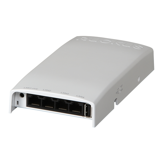
H500 Access Point
Quick Setup Guide
This Quick Setup Guide provides step-by-step instructions on how
to set up your Ruckus Wireless H500 Dual Band 802.11ac
Multimedia Wi-Fi Access Point Wall Switch. After completing the
steps described in this Guide, you will be able to access the Wi-Fi
Wall Switch and begin providing wired and wireless network
access to users. The rest of this document refers to the H500
Access Point Wall Switch as the H500.
The H500 has many options:
•
It can be mounted on a standard USA- or EU-style single-
gang wall outlet box.
•
It can be powered by a customer-supplied IEEE 802.3af/at-
compliant PoE switch or injector, or can be powered by an
optional customer-ordered DC power adapter.
•
It has side cutouts for one or two Ethernet bypass cables. The
mounting bracket has locating hooks to keep the bypass
cables aligned with the cutouts when attaching the H500 to
the mounting base.
•
It can have a low-power (0.5W or less) customer-supplied
USB adapter plugged in. The USB adapter is very difficult to
remove after the H500 is attached to the mounting base.
Note: The H500 requires Ruckus Wireless base image 100.0.1
firmware or later. Managed H500 deployments require RuckOS
for SmartCell Gateway (SCG) 3.1 or later, RuckOS for virtual
SmartCell Gateway (vSCG) 3.0 or later, or ZoneFlex (ZF) 9.10 or
later.
Copyright © 2014 Ruckus Wireless, Inc.
Draft Published 11 December 2014, Part Number 800-70718-001 Rev A
A
P
P
D
BOUT
OWERING
ERIPHERAL
The H500 can supply power to USB and PoE-powered devices,
and the power supplied depends on the PoE power supplied to
the H500.
•
The USB port is intended for low-power devices such as BLE
beacons. The maximum power that the USB port can supply
is 0.5W.
•
The PoE port is intended for PoE-powered peripheral devices
such as IP telephones.
H500 Power Options and Available Power Out for PoE Out
and USB
H500 Power Source
Power Available for PoE Out
and USB
802.3af PoE
5W total
802.3at PoE
12.95W PoE Out (802.3af
Class 3) and
0.5W USB
DC power adapter (sold
12.95W PoE Out (802.3af
separately)
Class 3) and
0.5W USB
T
G
O
L
HIS
UIDE IN
THER
ANGUAGES
请从以下网站获得该指南的简体中文版
•
https://support.ruckuswireless.com.
•
Vous trouverez la version française de ce guide à l'adresse
suivante https://support.ruckuswireless.com.
こ の ガ イ ド の日本語版は
•
https://support.ruckuswireless.com
で ご 覧 く だ さ い。
이 가이드의 한국어 버전은 웹 사이트
•
(https://support.ruckuswireless.com) 에서 확인하시기 바랍니
다 .
•
Veja a versão em português (Brasil) deste guia em
https://support.ruckuswireless.com.
•
Puede ver la versión en español (América Latina) de esta guía
en
https://support.ruckuswireless.com.
B
EVICES
EFORE
Before deploying Ruckus Wireless products, please check for the
latest software and the release documentation.
•
User Guides and Release Notes are available at
http://support.ruckuswireless.com/documents.
•
Software Upgrades are available at
http://support.ruckuswireless.com/software.
•
Open Source information is available at
http://opensource.ruckuswireless.com.
•
Software License and Limited Warranty are available at
http://support.ruckuswireless.com/warranty.
P
ACKAGE
•
H500 Access Point Wall Switch
•
Mounting bracket
•
Two 10mm M3x0.5 thread Torx flat head machine screws
•
Two 1" 6-32 thread Phillips pan head machine screws
•
Product warranty statement
•
Registration card
•
Regulatory flyer
•
Declaration of Conformity, if required
•
This Quick Setup Guide
Y
B
OU
EGIN
C
ONTENTS
Page 1 of 4
Advertisement
Table of Contents

Related Manuals for Ruckus Wireless H500


Summary of Contents for Ruckus Wireless H500
- Page 1 Wall Switch and begin providing wired and wireless network • Two 10mm M3x0.5 thread Torx flat head machine screws access to users. The rest of this document refers to the H500 802.3at PoE 12.95W PoE Out (802.3af Access Point Wall Switch as the H500.
- Page 2 (when this process is complete). • A computer with an Ethernet port and a wireless card port to the PoE In port on the back of the H500. • One Cat 5e or better Ethernet cable Select Use the following IP address (if it is not already...
- Page 3 Default H500 Access Point Settings (for your reference) Figure 3: Mounting bracket the H500 should be directly connected to your computer (through the PoE In Ethernet port on the back of the H500) and powered Network Names (SSIDs) Wireless1-Wireless8 (2.4GHz on, ready for setup.
- Page 4 To be determined. If you are installing a customer-supplied USB adapter, then plug it securely into the USB jack on the bottom of the H500. Pull the uplink Ethernet cable from your LAN through the outlet box, and plug it into the back of the H500.
Need help?
Do you have a question about the H500 and is the answer not in the manual?
Questions and answers