Ruckus Wireless ZoneFlex 7055 Quick Setup Manual
Dual-band multimedia wi-fi wall switch
Hide thumbs
Also See for ZoneFlex 7055:
- User manual (187 pages) ,
- User manual (193 pages) ,
- Quick setup manual (2 pages)
Advertisement
Quick Links
ZoneFlex 7055
Dual-Band Multimedia Wi-Fi
Wall Switch
Quick Setup Guide
This Quick Setup Guide provides step-by-step instructions
on how to set up your Ruckus Wireless ZoneFlex 7055
Multimedia Wi-Fi Wall Switch. After completing the steps
described in this Guide, you will be able to access the Wi-Fi
Wall Switch and begin providing wired and wireless network
access to users.
The ZoneFlex 7055 requires a minimum of Zone-
NOTE:
Flex firmware version 9.6 and above to operate.
T
G
O
L
HIS
UIDE IN
THER
ANGUAGES
请从以下网站获得该指南的简体中文版
https://support.ruckuswireless.com.
請造訪以下網址,取得此手冊的繁體中文版本
https://support.ruckuswireless.com.
Vous trouverez la version française de ce guide à l'adresse
suivante https://support.ruckuswireless.com.
こ の ガ イ ド の⽇本語版は
https://support.ruckuswireless.com
で ご 覧 く だ さ い。
이 가이드의 한국어 버전은 웹 사이트
(https://support.ruckuswireless.com) 에서 확인하시기 바랍니다 .
Veja a versão em português (Brasil) deste guia em
https://support.ruckuswireless.com.
Puede ver la versión en español (América Latina) de esta guía en
https://support.ruckuswireless.com
B
Y
B
EFORE
OU
EGIN
Before deploying Ruckus Wireless products, please check for
the latest software and the release documentation.
•
Release Notes and User Guides are available at
http://support.ruckuswireless.com/documents
•
Software Upgrades, Open Source Information and Product
Warranty/Software License Agreement documents are also
available at:
http://support.ruckuswireless.com/
P
C
ACKAGE
ONTENTS
•
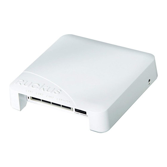
ZoneFlex 7055 Wi-Fi Wall Switch (Access Point)
•
Mounting bracket
•
(2) Low-profile Phillips head mounting screws
•
(2) Torx bracket screws
•
Regulatory flyer
•
This Quick Setup Guide
S
R
ETUP
EQUIREMENTS
•
A Phillips screwdriver
•
A T10 Torx screwdriver
•
A notebook with an Ethernet port and a wireless card.
•
A standard US or EU-style wall outlet box, with an Ethernet
cable run through the wall from your LAN to the outlet box.
•
One of the following:
•
An IEEE 802.3af/at-compliant PoE switch.
•
An IEEE 802.3af/at-compliant PoE injector.
•
An optional DC power adapter (Ruckus part #902-
0170-XX10, sold separately)
\
WARNING!
DO NOT connect a PoE injector to any of the
four front ports, as this can seriously damage the device.
PoE in power supply should only be connected to the
In LAN/Uplink
port on the rear of the device.
S
1: P
TEP
REPARE
S
ETUP
NOTE:
.
The following instructions assume Windows 7 as the
operating system. Procedures for other OS's are similar.
Copyright © 2013 Ruckus Wireless, Inc.
Published June 2013, Part Number 800-70432-001 Rev B
PoE
Y
C
AP
OUR
OMPUTER FOR
1
On your Windows 7 computer, open the Network Con-
nections (or Network and Dial-up Connections) control
panel:
Start > Control Panel > Network and Sharing Cen-
ter > Change Adapter Settings
2
When the Network Connections window appears, right-
Local Area Connection
click the icon for
select
Properties
.
When the Local Area Connection Properties dialog box
Internet Protocol Version 4 (TCP/
appears, select
IPv4)
from the scrolling list, and then click
The TCP/IP Properties dialog box appears.
3
Select
Use the following IP address
already selected), and then make the following entries:
•
IP address
: 192.168.0.22 (or any address in the
192.168.0.x network--other than 192.168.0.1, which is
in use by the AP)
Subnet mask
•
: 255.255.255.0
Default gateway
•
: 192.168.0.1
Leave the DNS server fields empty.
4
Click
OK
to save your changes, and exit the TCP/IP Prop-
erties dialog box, and the Local Area Connection Proper-
ties dialog box. Your changes are put into effect
immediately.
S
2: C
AP
Y
TEP
ONNECT THE
TO
OUR
1
Remove the AP from its packaging and place it near your
computer.
2
Connect one end of an Ethernet cable to the
LAN 5/Uplink
port on the rear of the AP, and connect
the other end to a PoE switch or the
the PoE injector.
•
If PoE power is not available, the AP can be powered
using an optional DC power adapter (Ruckus part
#902-0170-XX10, sold separately)
3
Using another Ethernet cable, connect one end to your
computer's network port, and connect the other end to
another port on the PoE switch or to the
work
port on the PoE injector.
4
Provide power to the PoE injector/switch.
PWR
5
Verify that the
LED is steady green.
NOTE:
If PoE is not available, the 7055 can be powered
by Ruckus Wireless power adapter (part number 902-
0170-xx10).
, and then
Properties
.
option (if it is not
C
OMPUTER
PoE In
Power Out
port on
Data In/Net-
Advertisement

Subscribe to Our Youtube Channel
Related Manuals for Ruckus Wireless ZoneFlex 7055


Summary of Contents for Ruckus Wireless ZoneFlex 7055
- Page 1 A standard US or EU-style wall outlet box, with an Ethernet already selected), and then make the following entries: on how to set up your Ruckus Wireless ZoneFlex 7055 cable run through the wall from your LAN to the outlet box.
- Page 2 AP will be installed. Prepare the electrical outlet box. Rear view The ZoneFlex 7055 can be mounted to a variety of com- monly used electrical outlet box formats, including US- Copyright © 2013 Ruckus Wireless, Inc.
Need help?
Do you have a question about the ZoneFlex 7055 and is the answer not in the manual?
Questions and answers