Icom IC-7851 Instruction Manual
Hide thumbs
Also See for IC-7851:
- Servise manual (179 pages) ,
- Quick start manual (9 pages) ,
- Instruction manual (3 pages)
Table of Contents
Advertisement
Quick Links
Download this manual
See also:
Service Manual
Advertisement
Chapters
Table of Contents

Subscribe to Our Youtube Channel
Related Manuals for Icom IC-7851


Summary of Contents for Icom IC-7851
-
Page 1: Instruction Manual
THE TRANSCEIVER i7851 Instruction Manual A-7205H-1EX-0a Printed in Japan © 2015 Icom Inc. - Page 2 We are proud to have developed the IC-7851 for your amateur radio activities, and hope it brings you years of enjoyable operation. Please read this instruction manual thoroughly before using the IC-7851.
-
Page 3: Explicit Definitions
NOTE ry, fire or electric shock. TRADEMARKS Icom, Icom Inc. and the Icom logo are registered trademarks of Icom Incorporated (Japan) in Japan, the United States, the United Kingdom, Germany, France, Spain, Russia and/or other countries. This product includes “zlib” open source software, and is licensed according to the open source software li- cense. - Page 4 OFF and remove the power cable if it emits an DO NOT place the transceiver against walls or abnormal odor, sound or smoke. Contact your Icom putting anything on top of the transceiver. This may dealer or distributor for advice.
-
Page 5: Fcc Information
CAUTION: Changes or modifications to this device, more of the following measures: not expressly approved by Icom Inc., could void your authority to operate this device under FCC regula- • Reorient or relocate the receiving antenna. - Page 6 FUNCTIONS AND FEATURES of Adobe ® Reader ® The following functions and features can be used with Adobe ® Reader ® . • Keyword search • Find screen Click “Find (Ctrl+F)” or “Advanced Search (Shift+Ctrl+F)” in the Edit menu to open the search screen. This is convenient when search- •...
-
Page 7: Band Edge Warning Beep
DESCRIPTION INFORMATION This instruction manual is described based on the following manner. “ ” (Quotation marks): Used to indicate icons, setting items, and screen titles displayed on the screen. [ ] (brackets): Used to indicate keys, dials, and knobs. Routes to the Set mode and setting screen descriptions Routes to the mode, setting screen and the setting items are described in the following manner. -
Page 8: Supplied Accessories
SUPPLIED ACCESSORIES † AC power cable ..........1 Rack mounting handles ........ 1 pair Screws for rack mounting handles ....1 set SD card ..............1 Feet .............. 1 pair Spare fuse (2 A) ..........1 RCA plugs ............2 DC plug ............... -
Page 9: Table Of Contents
D Rear panel (External keypad and meter) ………………………… 3-6 ■ inear amplifier connections ………………………………………… 3-7 D Connecting the IC-PW1/EURO …………………………………… 3-7 D Connecting a non-Icom linear amplifier …………………………… 3-7 ■ ransverter jack information …………………………………………… 3-8 ■ SK and AFSK (SSTV) connections ………………………………… 3-8... - Page 10 TABLE OF CONTENTS ■ icrophones (optional products) ……………………………………… 3-9 D SM-50 ………………………………………………………………… 3-9 D SM-30 ………………………………………………………………… 3-9 D HM-36 ………………………………………………………………… 3-10 BASIC OPERATION Section 4 ■ hen first applying power …………………………………………… 4-2 ■ ower ON ……………………………………………………………… 4-3 D esetting the CPU (initial setup) …………………………………… 4-3 ■...
- Page 11 TABLE OF CONTENTS ■ lectronic keyer functions ……………………………………………… 5-9 emory keyer screen ……………………………………………… 5-10 D diting a Keyer memory …………………………………………… 5-11 D ontest number set mode ………………………………………… 5-12 D eyer set mode ……………………………………………………… 5-13 ■ perating RTTY (FSK) ………………………………………………… 5-14 D bout the RTTY reverse mode ……………………………………...
- Page 12 TABLE OF CONTENTS Functions for Receive Section 7 ■ reamplifier ……………………………………………………………… 7-2 ■ ttenuator ……………………………………………………………… 7-2 ■ IT function ……………………………………………………………… 7-3 ï RIT monitor function ………………………………………………… 7-3 ■ GC function control …………………………………………………… 7-4 ï Selecting the preset value ………………………………………… 7-4 ï...
- Page 13 TABLE OF CONTENTS ■ eleting a recorded audio file ………………………………………… 9-6 ■ eleting a recorded audio folder ……………………………………… 9-6 ■ nstant replay function ………………………………………………… 9-7 ■ ecording the communication audio ………………………………… 9-8 ■ laying back the recorded audio ……………………………………… 9-8 ■...
- Page 14 TABLE OF CONTENTS ■ emo pads ……………………………………………………………… 11-7 D ntering frequencies and operating modes into Memo pads …… 11-7 D alling up a frequency and operating mode from Memo pads … 11-8 D sing the Memo pad list screen …………………………………… 11-8 SCANS Section 12 ■...
- Page 15 TABLE OF CONTENTS SET MODE Section 15 ■ et mode description …………………………………………………… 15-2 D et mode operation ………………………………………………… 15-2 D creen arrangement ………………………………………………… 15-3 ■ evel set screen ………………………………………………………… 15-4 ■ CC set screen ………………………………………………………… 15-6 ■ isplay set screen …………………………………………………… 15-10 ■...
- Page 16 TABLE OF CONTENTS SPECIFICATIONS AND OPTIONS Section 19 ■ pecifications …………………………………………………………… 19-2 D General ……………………………………………………………… 19-2 D Transmitter …………………………………………………………… 19-2 D Receiver ……………………………………………………………… 19-3 D Antenna tuner ………………………………………………………… 19-3 ■ ptions ………………………………………………………………… 19-4 CONNECTOR INFORMATION Section 20 ■ CC socket ……………………………………………………………… 20-2 ■...
-
Page 17: Panel Description Section
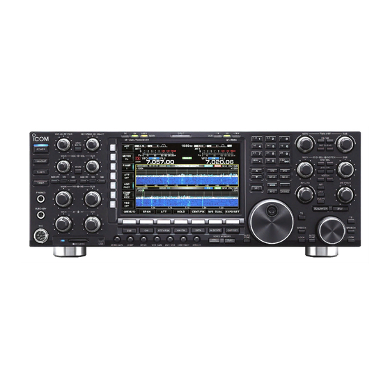
PANEL DESCRIPTION Section ■ ront panel ……………………………………………………………… 1-2 ■ ear panel ……………………………………………………………… 1-12 ■ isplay …………………………………………………………………… 1-14 ■ creen menu arrangement …………………………………………… 1-16... -
Page 18: Rear Panel.
PANEL DESCRIPTION ■ Front panel q POWER KEY [POWER] r TIMER KEY [TIMER] (pp. 4-3, 14-6) (p. 14-5) ➥ Push to turn ON or OFF the sleep or daily timer First, turn ON the internal power supply. The internal function. power supply switch is located on the rear panel. - Page 19 PANEL DESCRIPTION !9 ELECTRONIC CW KEYER SPEED CONTROL u MICROPHONE CONNECTOR [MIC] [KEY SPEED] Connect an optional microphone. (p. 5-7) • See page 3-4 for appropriate microphones. Rotate to adjust the internal electronic CW keyer’s • See page 20-3 for microphone connector information. speed to between 6 wpm (minimum) and 48 wpm (maximum).
- Page 20 PANEL DESCRIPTION ■ Front panel (Continued) @8 MODE KEYS @3 AGC CONTROL [AGC] (p. 7-4) Rotate to adjust the continuously-variable AGC cir- Selects the desired mode. (p. 4-10) • The Voice synthesizer announces the selected mode. cuit time constant. • To use the [AGC] control, push the appropriate band’s (p.
- Page 21 PANEL DESCRIPTION #0 MULTI-FUNCTION KEYS Push to select the functions indicated in the display to the right of these keys. • Functions vary, depending on the operating mode. ➥ Push to select the ANT1, ANT2, ANT3 or ➥ Push to activate and then select the ANT4 antenna connector.
- Page 22 PANEL DESCRIPTION ■ Front panel (Continued) $5 $4 #3 NOISE REDUCTION KEY [NR] #1 SQUELCH CONTROL [SQL] (p. 4-4) (p. 7-12) Rotate to adjust the squelch threshold level. The Push to turn the DSP noise reduction ON or OFF. • The [NR] indicator above this key lights white when the squelch removes noise output from the speaker function is activated.
- Page 23 PANEL DESCRIPTION #8 MINI SPECTRUM SCOPE KEY [M.SCOPE] $4 SUB BAND ACCESS KEY [SUB] (p. 6-2) ➥ Push to t urn the Mini spectrum scope screen ON Push to select the Sub band readout. • The Sub band readout frequency is clearly displayed. or OFF.
- Page 24 PANEL DESCRIPTION ■ Front panel (Continued) %1 AUTOMATIC TUNING KEY [AUTO TUNE] %4 SPLIT KEY [SPLIT] (pp. 8-7, 8-8) ➥ Push to turn ON the Automatic tuning function in the Push to turn the split function ON or OFF. ➥ CW or AM mode.
- Page 25 (p. 4-6) ➥ Hold down for 1 second to select the Manual • Icom’s triple band stacking register memorizes 3 fre- notch width from wide, mid, or narrow. quencies in each band. ✔ What is the Notch function? ➥...
- Page 26 PANEL DESCRIPTION ■ Front panel (Continued) &5 &4 &3 &2 &1 &0 ^5 LOCK KEY [LOCK] ^9 RIT KEY [RIT] (p. 4-12) (p. 7-3) ➥ Push to turn the Dial lock function ON or OFF. Push to turn the RIT function ON or OFF. •...
- Page 27 PANEL DESCRIPTION &3 DIGITAL RF SELECTOR KEY [DIGI-SEL] (p. 7-12) Push to turn the digital RF preselector ON or OFF. • The [DIGI-SEL] indicator lights white when the preselec- tor is in use. &4 PASSBAND TUNING CONTROLS [TWIN PBT] (p. 7-5) Adjusts the receiver’s IF filter ‘passband width’...
-
Page 28: Rear Panel
!0 AC POWER SOCKET [AC] (p. 3-4) *: A USB flash drive or USB keyboard is not supplied Connects the supplied AC power cable to an AC re- by Icom. ceptacle. !1 EXTERNAL SPEAKER JACK MAIN [EXT-SP A] (p. 3-5) !2 EXTERNAL SPEAKER JACK SUB [EXT-SP B] (p. - Page 29 !7 ALC INPUT JACK [ALC] (p. 3-5) Activated by a voltage applied to [ACC 2] pin 6, or Connects to the ALC output jack of a non-Icom lin- when the transverter function is in use. (pp. 20-2, ear amplifier.
-
Page 30: Display
PANEL DESCRIPTION ■ Display q BAND WIDTH INDICATOR !0 IF FILTER INDICATOR (p. 7-5) Displays the passband width of the IF filter. Displays the selected IF filter number. w MODE INDICATOR !1 VFO/MEMORY CHANNEL INDICATOR (p. 4-5) Indicates the VFO mode or selected memory chan- Displays the selected mode. - Page 31 PANEL DESCRIPTION ■ Display (Continued) !4 LAN INDICATOR Displays when the Remote station accesses the transceiver through the LAN connector. (An optional RS-BA1 is required.) !5 MULTI-FUNCTION SCREEN Display screen for the Digital multi-function me- ter, Spectrum scope, Audio scope, Voice recorder, Memory channel, Scan, Memory keyer, RTTY de- coder, PSK decoder, IF filter selection, and Set modes.
-
Page 32: Creen Menu Arrangement
PANEL DESCRIPTION ■ Screen menu arrangement The following screens can be selected from the Start Pushing [EXIT/SET] several times returns to the Start screen. Choose the desired screen using the fol- screen. See page 15-3 for set mode arrangement. lowing guide. •... -
Page 33: Set Mode Items Section
SET MODE ITEMS Section ■ bout the Setting screen configuration ……………………………… 2-2 ■ COPE SET …………………………………………………………… 2-3 ■ OICE SET ……………………………………………………………… 2-4 ■ EYER 001 ……………………………………………………………… 2-4 ■ EYER CW-KEY ……………………………………………………… 2-5 ■ TTY LOG SET ………………………………………………………… 2-5 ■ TTY DECODE SET …………………………………………………… 2-5 ■... -
Page 34: Cope Set
SET MODE ITEMS ■ About the Setting screen configuration The transceiver Setting consists of the following items. SETTING SCREEN REF. SPECTRUM SCOPE SCOPE SET pp. 2-3, 6-10 VOICE MEMORY VOICE SET pp. 2-4, 9-13 MEMORY KEYER KEYER 001 pp. 2-4, 5-12 KEYER CW-KEY pp. -
Page 35: Cope Set
SET MODE ITEMS ■ SCOPE SET SCOPE [F-1] EXPD/SET [F-7] ITEMS DESCRIPTIONS RANGE OR VALUE REF. Scope during Tx (CENTER Type) Transmit signal spectrum indication setting. OFF, ON p. 6-10 Max Hold Peak level holding function setting. OFF, 10s Hold, ON CENTER Type Display Center frequency setting when using the Filter Center,... -
Page 36: Oice Set
SET MODE ITEMS ■ VOICE SET VOICE [F-2] SET [F-7] ITEMS DESCRIPTIONS RANGE OR VALUE REF. VOICE 1st Menu VOICE-Root, VOICE-TX Root screen selection that displays first after p. 9-13 [VOICE](F) is pushed. VOICE TX Auto Monitor Automatic monitor function setting when OFF, ON transmitting a voice memory recording. -
Page 37: Eyer Cw-Key
SET MODE ITEMS ■ KEYER CW-KEY KEYER [F-3] [EXIT/SET] CW KEY [F-4] ITEMS DESCRIPTIONS RANGE OR VALUE REF. Keyer Repeat Time Interval setting for the memory keyer trans- 1 ~ 60 seconds p. 5-13 mission repeat. (in 1 second steps) Dot/Dash Ratio Dot/Dash ratio setting for ELE-KEY. -
Page 38: Can Set
SET MODE ITEMS ■ PSK LOG SET DECODE [F-3] <MENU1> [F-1] LOG [F-4] ITEMS DESCRIPTIONS RANGE OR VALUE REF. PSK Log PSK log use. OFF, ON p. 5-32 PSK Log File Type PSK log file saving format selection. Text, HTML PSK Log Storage Media Storage media selection for saving a PSK... -
Page 39: Evel Set
SET MODE ITEMS ■ LEVEL SET SET [F-7] LEVEL [F-1] ITEMS DESCRIPTIONS RANGE OR VALUE REF. SSB RX HPF/LPF HPF (High-Pass Filter)/LPF (Low-Pass Fil- HPF 100Hz ~ 2000Hz p. 15-4 ter) cut-off frequency setting for the received LPF 500Hz ~ 2400Hz audio in SSB mode. -
Page 40: Cc Set
SET MODE ITEMS ■ ACC SET SET [F-7] ACC [F-2] ITEMS DESCRIPTIONS RANGE OR VALUE REF. ACC-A AF/SQL Output Select [A ACC1] Band selection for the MAIN, SUB p. 15-6 AF/SQL signal output. ACC-B AF/SQL Output Select [B ACC1] ACC-A Output Select [A ACC1] Output signal setting. -
Page 41: Cc Set
SET MODE ITEMS ■ ACC SET(Continued) SET [F-7] ACC [F-2] ITEMS DESCRIPTIONS RANGE OR VALUE REF. USB Output Select [USB B] Output signal setting. AF, IF p. 15-7 USB AF/IF XFC Output (SPLIT Band selection for the MAIN, SUB AF/IF signal output while holding down [XFC] dur- ing split operation. -
Page 42: Display Set
SET MODE ITEMS ■ DISPLAY SET SET [F-7] DISP [F-3] ITEMS DESCRIPTIONS RANGE OR VALUE REF. LCD Unit Bright LCD unit brightness setting. 0 (dark) to 100% (bright) range p. 15-10 (in 1% steps) Backlight (Switches) Switch illumination brightness setting. Display Type Screen image type setting. -
Page 43: Ime Set
SET MODE ITEMS ■ TIME SET SET [F-7] TIME [F-4] ITEMS DESCRIPTIONS RANGE OR VALUE REF. Date Date setting. Year 2000~2099, p. 15-12 Month/Day 1- 1~12-31 Time (Now) Clock setting. 0:00~23:59 NTP Function NTP server client function setting. OFF, ON NTP Server Address NTP server address setting. - Page 44 SET MODE ITEMS ■ OTHERS SET(Continued) SET [F-7] OTHERS [F-5] ITEMS DESCRIPTIONS RANGE OR VALUE REF. Transverter Function Transverter function setting. ON, Auto p. 15-14 Transverter Offset Offset frequency setting for the transverter 0.000 to 99.999 MHz operation. (in 1 kHz steps) RTTY Mark Frequency RTTY mark frequency setting.
- Page 45 SET MODE ITEMS ■ OTHERS SET(Continued) SET [F-7] OTHERS [F-5] ITEMS DESCRIPTIONS RANGE OR VALUE REF. CW Normal Side Carrier point setting for the CW mode op- LSB, USB p. 15-16 eration. APF Type Audio filter shape setting for APF. SOFT, SHARP MIC AF Out Band selection for audio output from [MIC]...
- Page 46 SET MODE ITEMS ■ OTHERS SET(Continued) SET [F-7] OTHERS [F-5] ITEMS DESCRIPTIONS RANGE OR VALUE REF. CI-V USB Port Link setting for CI-V signal line between Link to [REMOTE], Unlink from p. 15-18 [USB B] and [REMOTE]. [REMOTE] CI-V USB Baud Rate CI-V data transfer speed setting for the re- 4800, 9600, 19200, 38400, mote control through [USB B].
- Page 47 SET MODE ITEMS ■ OTHERS SET(Continued) SET [F-7] OTHERS [F-5] ITEMS DESCRIPTIONS RANGE OR VALUE REF. 2nd DNS Server (Valid after Re- Secondary DNS (Domain Name System) p. 15-20 boot) server address setting for the IP remote control. Network Name Network name setting for the optional RS- Up to 15 characters BA1 operation.
-
Page 48: Oad Set
SET MODE ITEMS ■ LOAD SET SET [F-7] SD/USB [F-7] LOAD [F-1] ITEMS DESCRIPTIONS RANGE OR VALUE REF. Load Contents Loading contents setting. All, Select p. 10-9 ANT Memory Antenna memory load setting. YES, NO REF IN/OUT, REF Adjust, Filter Reference frequency signal, Reference fre- YES, NO quency adjustment value, and 1.2 kHz filter... -
Page 49: Ilter Shape Set
SET MODE ITEMS ■ VOX [VOX/BK-IN] ITEMS DESCRIPTIONS RANGE OR VALUE REF. VOX Delay VOX delay time setting. 0.0 ~ 2.0 sec. p. 8-3 (in 0.1 sec. steps) VOX Voice Delay VOX voice delay setting for VOX operation. OFF, Short, Mid, Long ■... -
Page 50: Installation And Connections Section
D Rear panel (External keypad and meter) ………………………… 3-6 ■ Linear amplifier connections ………………………………………… 3-7 D Connecting the IC-PW1/EURO …………………………………… 3-7 D Connecting a non-Icom linear amplifier …………………………… 3-7 ■ FSK and AFSK (SSTV) connections ………………………………… 3-8 ■ Microphones (optional products) ……………………………………… 3-9 D SM-50 …………………………………………………………………... -
Page 51: Unpacking
After unpacking, immediately report any damage to the delivering carrier or dealer. Keep the shipping car- tons. For a description and a diagram of accessory equip- ment included with the IC-7851, see ‘Supplied acces- sories’ on page vii of this manual. -
Page 52: Hexagonal Wrench
INSTALLATION AND CONNECTIONS ■ Connecting antenna For radio communications, the antenna is of critical importance, along with the output power and receiver sensitivity. Select antennas, such as a well-matched 50 Ω antenna, and feedline. If you use only one antenna, connect it to the [ANT1] connector. -
Page 53: Required Connections
INSTALLATION AND CONNECTIONS ■ Required connections D Front panel (Electronic keyer and microphone) CW key A straight or bug key can be used when the internal electronic keyer is turned OFF in keyer set mode. (p. 5-13) Microphones (pp. 3-9, 3-10) Optional Optional Optional... -
Page 54: Dvanced Connections
ACC sockets [RELAY], [ALC] (p.3-7) Used for remote control and trans- Used to connect to a (p. 20-2) ceive operation. non-Icom linear amplifier. The optional CT-17 is required when External speaker (p. 20-5) connecting a PC to [REMOTE]. SP-34 (optional) Impedance:... -
Page 55: D Rear Panel (External Keypad And Meter)
INSTALLATION AND CONNECTIONS ■ Advanced connections (Continued) D Rear panel (Optional products and external equipment) USB PORT Connects to a USB device such as keyboard, mouse, hub or memory (USB flash drive). • Turn OFF the transceiver’s power before connecting or disconnecting a USB device. •... -
Page 56: D Connecting The Ic-Pw1/Euro
RF OUTPUT RF INPUT 20-4 for details). Use an external relay unit when your non-Icom linear amplifier requires a control SEND voltage and/or current greater than specified. Non-Icom linear amplifier When using a linear amplifier that has a time delay between receiving and transmitting, a high SWR might cause the linear amplifier to malfunction. -
Page 57: Sk And Afsk (Sstv) Connections
RTTY. (p. 15-19) USB cable (Purchase separately) (2) When using the ACC socket or the microphone connector Example interface circuit for digital modes (Not provided by Icom) 2 k˘ 2 k˘ 10 k˘ Shield cable ¡When connecting to [ACC1] 10 k˘... -
Page 58: Microphones (Optional Products)
INSTALLATION AND CONNECTIONS ■ Microphones (optional products) D SM-50 q PTT SWITCH TOP VIEW Hold down to transmit, release to receive. w PTT LOCK SWITCH Push to lock the PTT switch in the transmit mode. e UP/DOWN SWITCHES [UP]/[DN] Change the selected readout frequency or memory channel. - Page 59 INSTALLATION AND CONNECTIONS ■ Microphones (optional products) (Continued) D HM-36 q PTT SWITCH Hold down to transmit, release to receive. w UP/DOWN SWITCHES [UP]/[DN] Change the selected readout frequency or memory channel. • Holding down continuously changes the frequency or memory channel.
-
Page 60: Basic Operation Section
BASIC OPERATION Section ■ hen first applying power …………………………………………… 4-2 ■ ower ON ……………………………………………………………… 4-3 D esetting the CPU (initial setup) …………………………………… 4-3 ■ djusting the Audio level ……………………………………………… 4-4 ■ djusting the Squelch level …………………………………………… 4-4 ■ djusting the RF gain ………………………………………………… 4-4 ■... -
Page 61: When First Applying Power
BASIC OPERATION ■ When first applying power Before first applying power, confirm the following con- nections or settings: • Antennas are properly connected. (p. 3-4) • A ground wire is properly connected. (p. 3-2) • External devices such as a liner amplifier, if used, are properly connected. -
Page 62: Ower On
BASIC OPERATION ■ Power ON Push [I/O] on the rear panel to turn ON the main [I/O] power. • The transceiver power is still OFF but the [POWER] indi- cator lights orange. • When first applying power, refer to the ‘Resetting the CPU (initial setup).’... -
Page 63: Djusting The Squelch Level
BASIC OPERATION ■ Adjusting the Audio level ➥ Rotate the [AF] control to adjust the audio output level. • Set a suitable audio level. Independently adjust the Main and Sub bands. [AF] MAIN, SUB ■ Adjusting the Squelch level Noise squelch: [SQL] MAIN, SUB In the FM mode, rotate the [SQL] control and adjust to the point where the noise just disappears and the RX... -
Page 64: Electing The Vfo Or Memory Mode
BASIC OPERATION ■ Selecting the Main and Sub bands IC-7851 has 2 identical receivers, Main and Sub. [MAIN] [SUB] The Main band is displayed on the left hand side, and the Sub band is displayed on the right hand side of the LCD. -
Page 65: Electing An Operating Band
BASIC OPERATION ■ Selecting an operating band The triple band stacking register provides three mem- Band keys ories for each band to store frequencies and operating modes. If a band key is pushed once, the last used frequency and operating mode are called up. When the key is pushed again, the next previous stored frequency and operating mode are called up. -
Page 66: Etting The Frequency
BASIC OPERATION ■ Setting the frequency The transceiver has several setting methods for conve- nient frequency setting. D Tuning with [DIAL] Select the desired band with the band keys. Band keys Rotate [MAIN DIAL] to set the desired frequency in the Main band. -
Page 67: Selecting The Fine Tuning Function
BASIC OPERATION ■ Setting the frequency (Continued) D Selecting the Fine tuning function The minimum tuning step of 1 Hz can be used for fine tuning. With the Quick tuning function OFF. q Hold down [TS] for 1 second. •... - Page 68 BASIC OPERATION D About the 1⁄4 tuning step function When operating in the SSB data, CW, RTTY or PSK modes, the ⁄ tuning function is selectable. When the function is ON, the dial speed is reduced to ⁄ of the normal speed, for finer tuning control.
-
Page 69: Selecting The Operating Mode
BASIC OPERATION ■ Selecting the Operating mode The following modes are selectable. • SSB (USB/LSB) and SSB data (USB data/LSB data) modes • CW and CW reverse (CW-R) modes • RTTY and RTTY reverse (RTTY-R) modes • PSK and PSK reverse (PSK-R) modes •... -
Page 70: Selecting The Meter Readout
BASIC OPERATION ■ Selecting the Meter readout The S/RF meter readout during transmit can be se- Signal strength level lected from the following items. readout 60dB readout 100 150 ) key several ➥ Push the Multi-function [METER]( Power level readout times to select the desired meter item. -
Page 71: Selecting The Meter Type
BASIC OPERATION ■ Selecting the Meter readout (Continued) D Selecting the meter type A total of 3 meter types are selectable. The meter types are Standard, Edgewise and Bar me- ters. Follow the instructions to select the meter type. Select the “Meter Type (Normal Screen)” item in the Display set screen. -
Page 72: Asic Transmit Operation
BASIC OPERATION Before transmitting, monitor your selected operating frequency to make sure you don’t cause interfer- ence to other stations on the same frequency. It’s good amateur practice to listen first, and then, even if nothing is heard, ask “is the frequency in use” once or twice, before you being operating. ■... -
Page 73: Transmit Power Limit
BASIC OPERATION ■ Basic transmit operation (Continued) D Adjusting the drive gain The drive gain is active for all modes except SSB with- out speech compressor. The [DRIVE] control adjusts the amplifying gain at the driver stage. q Push the Multi-function [METER]() key to select the ALC meter. -
Page 74: And Edge Warning Beep
BASIC OPERATION ■ Band edge warning beep This function allows you to hear a beep tone when you tune in or out of an amateur band’s frequency range. A regular beep sounds when you tune into a range, and a lower tone error beep will sound when you tune out of a range. -
Page 75: Entering The User Band Edge
BASIC OPERATION ■ Band edge warning beep (Continued) D Entering the user band edge NOTE: The duplicated frequency with the already registered frequency range, cannot be registered. Up to 30 frequency ranges can be set. • In the default setting, all frequency ranges that can be used, are entered. - Page 76 BASIC OPERATION • The Multi-function keys for entering the frequen- cy range: When inserting a blank line, push [p](F) or [q](F) to Multi-function keys Description select the line below the one where you want to insert a new line. And then push [INS](). Insert a line above the selected line •...
-
Page 77: Bout The 5 Mhz Frequency Band Operation (Usa Version Only)
BASIC OPERATION ■ About the 5 MHz frequency band operation (USA version only) Operation on the 5 MHz frequency band is allowed on To assist you in operating within the rules specified 5 discrete frequencies and must adhere to the follow- by the FCC, transmission is illegal on any frequen- ing: cies other than the five shown in the tables below. -
Page 78: Receive And Transmit Section
RECEIVE AND TRANSMIT Section ■ onvenient functions for Receive …………………………………… 5-2 ■ onvenient functions for Transmit …………………………………… 5-3 ■ perating SSB ………………………………………………………… 5-4 ■ perating CW …………………………………………………………… 5-5 D bout the CW pitch control ………………………………………… 5-6 D PF (Audio Peak Filter) operation ………………………………… 5-6 D djusting the Key speed ……………………………………………... -
Page 79: Convenient Functions For Receive
IF filter passband, to reject inter- • When the CW, RTTY, or PSK mode is selected: ference. The IC-7851 uses DSP for the PBT function. Moving both the [TWIN PBT] controls to the same po- Only the Manual notch can be used. -
Page 80: Convenient Functions For Transmit
This function provides hands-free operation. keying. The IC-7851 is capable of full break-in or semi Push [VOX/BK-IN] to turn the VOX function ON or ➥... -
Page 81: Operating Ssb
RECEIVE AND TRANSMIT ■ Operating SSB Before transmitting, monitor your selected operating [MIC] [TRANSMIT] Band keys frequency to make sure you don’t cause interference [RF PWR] TX indicator MAIN to other stations on the same frequency. Push a band key to select desired band. Push the Mode key [SSB] to select the SSB mode. -
Page 82: Operating Cw
RECEIVE AND TRANSMIT ■ Operating CW Before transmitting, monitor your selected operating [TRANSMIT] Band keys frequency to make sure you don’t cause interference [RF PWR] MAIN TX indicator to other stations on the same frequency. Push a band key to select the desired band. Push the Mode key [CW] to select the CW mode. -
Page 83: Apf (Audio Peak Filter) Operation
RECEIVE AND TRANSMIT ■ Operating CW (Continued) D About the CW pitch control The received CW audio pitch and CW side tone can be adjusted to suit your preference. This does not change the operating frequency. Rotate [CW PITCH] to suit your preference. •... -
Page 84: Cw Side Tone Function
RECEIVE AND TRANSMIT D Adjusting the Key speed When using the internal electric keyer, you can adjust [KEY SPEED] the Key speed. ➥ Rotate [KEY SPEED]. • The key speed popup appears. You can confirm the ad- justed speed by numeral. •... - Page 85 RECEIVE AND TRANSMIT ■ Operating CW (Continued) D About 137 kHz band operation (Europe version only) The 137 kHz band, between the 135.7 kHz to 137.8 kHz, operation in the CW mode is optionally available. The RF signal from [X-VERTER] is used for the 137 kHz band operation, and an external amplifier unit is necessary.
-
Page 86: Electronic Keyer Functions
RECEIVE AND TRANSMIT ■ Electronic keyer functions IC-7851 has a number of convenient functions for the built-in electronic keyer. The Multi-function screens are OFF: Push the Mode key [CW]. Push [KEYER](F). • The Memory keyer screen is displayed. Push [EXIT/SET]. -
Page 87: D Memory Keyer Screen
RECEIVE AND TRANSMIT ■ Electronic keyer functions (Continued) D Memory keyer screen [TRANSMIT] Preset characters can be sent using the Memory keyer screen. Contents of the memory keyer are entered in the Keyer edit screen. • Transmitting The Multi-function screens are OFF: Push the Mode key [CW]. -
Page 88: Editing A Keyer Memory
• Preset contents acters. Contents After editing the contents, push [EXIT/SET]. • Exits the Keyer edit screen. M1 CQ TEST CQ TEST DE ICOM ICOM TEST M2 UR 5NN✱ BK • Selectable characters (with [MAIN DIAL]) M3 CFM TU M4 QRZ? -
Page 89: Contest Number Set Mode
RECEIVE AND TRANSMIT ■ Electronic keyer functions (Continued) D Contest number set mode This mode is used to set the Number style, Count up trigger and Present number. • Setting contents The Multi-function screens are OFF: Push [KEYER](F). • The Memory keyer screen is displayed. Display the Memory keyer menu screen, then push [001](F). -
Page 90: Keyer Set Mode
RECEIVE AND TRANSMIT D Keyer set mode This Set mode is used to set the memory keyer repeat time, dash weight, paddle specifications, keyer type, and so on. • Setting contents The Multi-function screens are OFF: Push [KEYER](F). • The Memory keyer screen is displayed. Display the Memory keyer menu screen, then push [CW KEY](F). -
Page 91: Operating Rtty (Fsk)
[RF PWR] MAIN Band keys TX indicator coder is built-in to the IC-7851. When connecting a PC keyboard, you can operates RTTY without an external RTTY terminal or PC. If you would rather use your RTTY terminal, consult the equipment manual. -
Page 92: D About The Rtty Reverse Mode
RECEIVE AND TRANSMIT D About the RTTY reverse mode Received characters are occasionally garbled when Normal Reverse the received signal has the Mark and Space tones reversed. This reversal can be caused by incorrect 170 Hz 2125 Hz 2125 Hz 170 Hz TNC connections, setting, or commands. -
Page 93: Functions For The Rtty Decoder Display
RECEIVE AND TRANSMIT ■ Operating RTTY (FSK) (Continued) D Functions for the RTTY decoder display Push the Mode key [RTTY/PSK] to select the RTTY mode. • After the RTTY mode is selected, hold down [RTTY/PSK] for 1 second to toggle between the RTTY and RTTY-R modes. -
Page 94: Rtty Memory Transmission
RECEIVE AND TRANSMIT D Setting the decoder threshold level Adjust the RTTY decoder threshold level if some characters are displayed, even though no signal is re- ceived. Display the RTTY decode screen, then push [ADJ] (F). • RTTY threshold setting screen DECODE [F-3] ... - Page 95 RECEIVE AND TRANSMIT ■ Operating RTTY (FSK) (Continued) D Automatic transmission/reception setting Display the RTTY decode screen, then push [TX MEM](F). DECODE [F-3] TX MEM [F-4] • The RTTY memory screen is displayed. Push [EDIT](F). • The RTTY memory edit screen is displayed. Push [RT1..RT8](F) several times.
-
Page 96: Editing The Rtty Memory
Selects the Number input mode. RT1 MYCALLx2 ↵DE ICOM ICOM K↵ • Push to toggle between [123]() and [123]() RT2 MYCALLx3 ↵DE ICOM ICOM ICOM K↵ [Symbol](). RT3 QSLUR599 ↵QSL UR 599–599 BK↵ [Symbol]() Selects the Symbol input mode. ↵QSL DE ICOM ICOM UR 599–599... -
Page 97: Turning On The Rtty Log
RECEIVE AND TRANSMIT ■ Operating RTTY (FSK) (Continued) D Turning ON the RTTY log Turn ON the RTTY log to store your RTTY operating record, both TX and RX, onto an SD card or USB flash drive. Be sure to insert an SD card or USB flash drive, other- wise this function does not work. -
Page 98: Confirm The Rtty Log Contents
RECEIVE AND TRANSMIT D Confirm the RTTY log contents You can confirm the RTTY log contents on the trans- ceiver display. q Display the RTTY decode screen, then push [<MENU1>](F). DECODE [F-3] <MENU1> [F-1] Displays <MENU2> • The function menu changes to Menu 2. Push [LOG VIEW](F). -
Page 99: Rtty Decode Set Mode
RECEIVE AND TRANSMIT ■ Operating RTTY (FSK) (Continued) D RTTY decode set mode This Set mode is used to set the decode USOS func- tion, time stamp setting, and other RTTY settings. q Display the RTTY decode screen, then push [<MENU1>](F). - Page 100 RECEIVE AND TRANSMIT RTTY Font Color (Time Stamp) RTTY Auto CR+LF by TX (Default: ON) (Default: (R) 0 (G) 155 (B) 189) Selects sending a new line code (CR+LF) once when transmitting. Sets the text color for time stamp display. •...
-
Page 101: Operating Psk
RECEIVE AND TRANSMIT ■ Operating PSK A high-quality DSP-based PSK encoder/decoder is built into the IC-7851. You can connect a keyboard to the transceiver and operate PSK without a PC. (p. 3-6) This transceiver can be used in the PSK31 and PSK63 modes. - Page 102 RECEIVE AND TRANSMIT D Vector indicator and Waterfall display You can fine tune the PSK signal using the Vector tun- ing indicator and waterfall display. Slowly rotate the [MAIN DIAL]. PSK decode screen • • When a PSK signal is received, the vertical line appears on the waterfall display.
-
Page 103: Functions For The Psk Decoder Display
RECEIVE AND TRANSMIT ■ Operating PSK (Continued) D Functions for the PSK decoder display Push the Mode key [RTTY/PSK] to select the PSK mode. • After the PSK mode is selected, hold down [RTTY/PSK] for 1 second to toggle between the PSK and PSK-R modes. •... - Page 104 RECEIVE AND TRANSMIT D About the BPSK and QPSK modes The BPSK and QPSK modes are selectable in the PSK31 mode. • The BPSK (Binary Phase Shift Keying) mode is the most commonly used mode. • The QPSK (Quadrature Phase Shift Keying) mode has error correction capability to provide better de- coding than the BPSK mode in marginal conditions.
-
Page 105: D Setting The Decoder Threshold Level
In the PSK mode, hold down [RTTY/PSK] for 1 sec- Mode keys ond to select the PSK and PSK-R modes. D AFC/NET functions IC-7851 has an AFC (Auto Frequency Control) NOTE: The AFC function may not tune the signal function. This is convenient to tune the PSK signal. -
Page 106: Psk Memory Transmission
RECEIVE AND TRANSMIT D PSK memory transmission Preset characters can be sent using the PSK memory. TX indicator MAIN Contents of the memory are entered in the PSK memory edit screen. The Multi-function screens are OFF: Push [DECODE](F). • The PSK decode screen is displayed. Push [TX MEM](F) to select the PSK memory screen. - Page 107 RECEIVE AND TRANSMIT ■ Operating PSK (Continued) D Automatic transmission/reception setting Display the PSK decode screen, then push [TX MEM](F). DECODE [F-3] TX MEM [F-4] • The PSK memory screen is displayed. Push [EDIT](F). • The PSK memory edit screen is displayed. Push [PT1..PT8](F) several times.
-
Page 108: Editing The Psk Memory
[DEL](F) Deletes a character. ↵73 GL SK↵ PT5 73 GL SK [SPACE](F) Enters a space. PT6 CQ CQ CQ ↵CQ CQ CQ DE Icom Icom Icom K↵ Toggles between the Name (Title) and [t u](F) ↵My transceiver is IC–7851 & Antenna Content items. -
Page 109: Turning On The Psk Log
RECEIVE AND TRANSMIT ■ Operating PSK (Continued) D Turning ON the PSK log Turn ON the PSK log to store your PSK operating re- cord, both TX and RX, onto an SD card or USB flash drive. Be sure to insert an SD card or USB flash drive, other- wise this function does not work. -
Page 110: Confirm The Psk Log Contents
RECEIVE AND TRANSMIT D Confirm the PSK log contents You can confirm the PSK log contents on the trans- ceiver display. q Display the PSK decode screen, then push [<MENU1>](F). DECODE [F-3] <MENU1> [F-1] Displays <MENU2> • The function menu changes to Menu 2. Push [LOG VIEW](F). -
Page 111: Psk Decode Set Mode
RECEIVE AND TRANSMIT ■ Operating PSK (Continued) D PSK decode set mode This Set mode is used to set the FFT scope setting, time stamp setting, and so on. q Display the PSK decode screen, then push [<MENU1>](F). DECODE [F-3] <MENU1> [F-1] Displays <MENU2> •... - Page 112 RECEIVE AND TRANSMIT PSK Font Color (Recieve) (Default: (R) 128 (G) 255 (B) 128) Sets the text color for received characters. • The color is set in the RGB format. • Push [ t u](F) to select R (Red), G (Green) and B (Blue).
-
Page 113: Operating Am Or Fm
RECEIVE AND TRANSMIT ■ Operating AM or FM Before transmitting, monitor the operating frequency to make sure transmitting won’t cause interference to other stations on the same frequency. Push a band key to select the desired band. [MIC] [TRANSMIT] Band keys Push the Mode key [AM/FM] to select the AM or FM [RF PWR] TX indicator MAIN... -
Page 114: Repeater Operation
RECEIVE AND TRANSMIT ■ Repeater operation SPLIT indicator Band keys A repeater amplifies received signals and retransmits them on a different frequency. When using a repeater, the transmit frequency is shifted from the receive fre- quency by an offset amount. A repeater can be ac- cessed using split frequency operation with the shift frequency set to the repeater’s frequency offset. -
Page 115: Repeater Tone Frequency Setting
RECEIVE AND TRANSMIT ■ Repeater operation (Continued) D Repeater tone frequency setting Some repeaters require subaudible tones to be ac- cessed. Subaudible tones are superimposed on your normal signal, and must be set in advance. The trans- () Multi-function keys ceiver has 50 tones from 67.0 Hz to 254.1 Hz. -
Page 116: Tone Squelch Operation
RECEIVE AND TRANSMIT ■ Tone squelch operation () Multi-function keys The tone squelch opens only when you receive a sig- nal containing a matching subaudible tone in the FM mode. You can silently wait for calls from others using the same tone. -
Page 117: Data Mode (Afsk) Operation
RECEIVE AND TRANSMIT ■ Data mode (AFSK) operation When operating AMTOR or PACKET with a PC appli- cation software, consult the manual that comes with the software. Before transmitting, monitor the operating frequency to make sure transmitting won’t cause interference to other stations on the same frequency. -
Page 118: Pectrum Scope Screen ...................................................... 6-2 S D Perating The Spectrum Scope
SCOPE OPERATION Section ■ pectrum scope screen ……………………………………………… 6-2 D perating the Spectrum scope …………………………………… 6-3 D enter mode ………………………………………………………… 6-4 D ixed mode …………………………………………………………… 6-5 D ual scope screen …………………………………………………… 6-6 ini scope screen …………………………………………………… 6-6 D cope attenuator …………………………………………………… 6-7 D djusting the Reference level ………………………………………... -
Page 119: Spectrum Scope Screen
They are generated in the internal scope circuit and strengths of various signals. do not indicate a transceiver malfunction. IC-7851 has two spectrum scope modes. One is the Center mode, and another one is the Fixed mode. You can also select Dual scope, Single scope, and Waterfall display ON or OFF for your convenience. - Page 120 SCOPE OPERATION D Operating the Spectrum scope The Multi-function screens are OFF: Push [SCOPE](F). • The Spectrum scope screen is displayed. Function Action <MENU1> Selects the Function menu. <MENU2> When the Center mode is selected, selects the scope span. [EXIT/SET] (F) Function keys •...
-
Page 121: Center Mode
SCOPE OPERATION ■ Spectrum scope screen (Continued) D Center mode Displays signals around the operating frequency within the selected span. The operating frequency is always displayed in the center of the screen. The Multi-function screens are OFF: Push [SCOPE](F). •... -
Page 122: Fixed Mode
SCOPE OPERATION D Fixed mode Displays signals within a specified frequency range. The selected frequency band activity can be observed at a glance when using this mode. The Multi-function screens are OFF: Push [SCOPE](F). • The Spectrum scope screen is displayed. Push [CENT/FIX](F). -
Page 123: Dual Scope Screen
SCOPE OPERATION ■ Spectrum scope screen (Continued) D Dual scope screen This transceiver has a Dual scope mode that simul- taneously displays the Main and Sub scopes during Dualwatch operation. You can select the “Over/Under” or “Side by Side” lay- out in the Scope set screen. -
Page 124: Scope Attenuator
SCOPE OPERATION D Scope attenuator While operating in the band with a high noise floor, set the Scope attenuator to reduce the noise level. • Even if the Scope attenuator is ON, it does not affect the receiver sensitivity. The Multi-function screens are OFF: Push [SCOPE](F). - Page 125 SCOPE OPERATION ■ Spectrum scope screen (Continued) D Adjusting the Reference level When monitoring a weak signal that is buried in the noise floor, or monitoring a strong signal but some stronger signals is nearby, adjust the Reference level of the screen helps to see these signals. •...
-
Page 126: Sweep Speed
SCOPE OPERATION D Sweep speed Select the sweep speed to change the FFT (Fast Fou- rier Transform) scope renew speed and the waterfall speed. • If you want to change only the waterfall speed, you can select “SLOW,” “MID,” or “FAST” in the Scope set screen. -
Page 127: Scope Set Screen
SCOPE OPERATION ■ Spectrum scope screen (Continued) D Scope set screen This Set screen is used to set the waveform color, Scope range for the Fixed mode, and so on. Display the Spectrum scope screen, then hold down [EXPD/SET](F) for 1 second. SCOPE [F-1] ... -
Page 128: Waterfall Size (Expand Scope)
SCOPE OPERATION Waveform Type Waterfall Speed (Default: Fill) (Default: MID) Select the outline waveform display for the Spectrum Select the Waterfall speed. scope. • SLOW: Sets the waterfall speed to SLOW. • Fill: The waveform is drawn only in color. •... - Page 129 SCOPE OPERATION ■ Spectrum scope screen (Continued) Fixed Edges (0.03 – 1.60) Fixed Edges (8.00 – 11.00) (Default: 0.500–1.500 MHz) (Default: 10.100–10.150 MHz) (Default: 0.500–1.500 MHz) (Default: 10.100–10.130 MHz) (Default: 0.500–1.500 MHz) (Default: 10.130–10.150 MHz) Set the Upper and Lower Edge frequencies for the Set the Upper and Lower Edge frequencies for the Fixed mode.
- Page 130 SCOPE OPERATION Fixed Edges (22.00 – 26.00) (Default: 24.890–24.990 MHz) (Default: 24.890–24.930 MHz) (Default: 24.930–24.990 MHz) Set the Upper and Lower Edge frequencies for the Fixed mode. Three edges are assigned to each band. Push [EDGE](F) to select the edge. •...
-
Page 131: Usb Mouse Operation
SCOPE OPERATION ■ Spectrum scope screen (Continued) D USB mouse operation If you connect a USB mouse to the transceiver, a mouse pointer appears on the Spectrum scope screen. Now, you can change the frequency or settings by us- ing the mouse. •... -
Page 132: Audio Scope Screen
SCOPE OPERATION ■ Audio scope screen This audio scope allows you to display the received signal’s frequency component on the FFT scope, and its waveform components on the Oscilloscope. The FFT scope has an waterfall. NOTE: When the Monitor function is ON, you can see the TX audio on the Audio scope. -
Page 133: Audio Scope Set Mode
SCOPE OPERATION ■ Audio scope screen (Continued) D Audio scope set mode This set mode is used to set the FFT scope waveform type, color, Waterfall display and oscilloscope wave- form color. Display the Audio scope screen, then hold down [SET](F) for 1 second. -
Page 134: Functions For Receive Section
FUNCTIONS FOR RECEIVE Section ■ reamplifier ……………………………………………………………… 7-2 ■ ttenuator ……………………………………………………………… 7-2 ■ IT function ……………………………………………………………… 7-3 ï IT monitor function ………………………………………………… 7-3 ■ GC function control …………………………………………………… 7-4 ï electing the preset value ………………………………………… 7-4 ï djusting the AGC time constant ………………………………… 7-4 ï... -
Page 135: Ttenuator
FUNCTIONS FOR RECEIVE ■ Preamplifier The preamp amplifies received signals in the receiver front end to improve the signal-to-noise ratio and sen- sitivity. Set this to P.AMP 1 or P.AMP 2 when receiving weak signals. ) key several times ➥ Push the Multi-function [P.AMP]( to turn ON preamp 1 or preamp 2, or to turn OFF (≈) Multi-function keys... -
Page 136: Rit Function
FUNCTIONS FOR RECEIVE ■ RIT function ∂ [RIT/ [RIT] The RIT (Receive Increment Tuning) function compen- sates for differences in frequencies of other stations. The function shifts the receive frequency up to ±9.99 kHz in 10 Hz steps, without moving the transmit frequency. Push [RIT] to turn ON the RIT function. -
Page 137: Gc Function Control
FUNCTIONS FOR RECEIVE ■ AGC function control [AGC] control (≈) Multi-function keys The AGC (Automatic Gain Control) controls receiver gain to produce a constant audio output level, even when the received signal strength varies greatly. The transceiver has three preset AGC settings (time constants: fast, mid, slow) for non-FM modes. -
Page 138: Win Pbt Operation
In general, the PBT (Passband Tuning) electronically narrows the IF passband width by shifting the IF fre- quency to slightly outside of the IF filter passband, to reject interference. The IC-7851 uses DSP for the PBT function. You can watch the nearby intended signal using the spectrum scope. -
Page 139: If Filter Selection
FUNCTIONS FOR RECEIVE ■ IF filter selection [FILTER] MAIN, SUB The transceiver has 3 IF filter passband widths for each mode, and are selectable in the Filter screen. You can toggle the IF filter between FIL1 (Wide), FIL2 (Mid) and FIL3 (Narrow) by pushing [FILTER]. The IF filter passband widths for each mode can be changed in the Filter screen. -
Page 140: Dsp Filter Shape
D Roofing filter selection • Roofing filter screen IC-7851 has 1.2, 3, 6 and 15 kHz roofing filters for the 1st IF frequency. The roofing filter provides interfer- ence reduction from nearby strong signals. ➥ Push [ROOFING](F) to set the desired filter width to 1.2, 3, 6, or 15 kHz... - Page 141 ■ IF filter selection (Continued) D 1.2 kHz Filter calibration IC-7851 has the 1.2 kHz Optimum Roofing Filter • When selecting “1.2 k” Roofing filter operating at 64 MHz. The characteristic of this Roofing Filter may slightly vary, depending on the operating en- vironment or after long usage.
-
Page 142: Filter Shape Set Mode
FUNCTIONS FOR RECEIVE ■ IF filter selection (Continued) D Filter shape set mode • Filter shape set screen The DSP filter shape for SSB, SSB data and CW can be independently set to soft or sharp. Hold down [SHAPE](F) for 1 second. •... -
Page 143: Dualwatch Operation
FUNCTIONS FOR RECEIVE ■ Dualwatch operation [SPLIT] Dualwatch simultaneously monitors two frequencies. [CHANGE] [DUALWATCH] IC-7851 has 2 independent receiver circuits, the Main and Sub bands, so that you can use Dualwatch with no compromises, even on different bands and modes. -
Page 144: Noise Blanker
FUNCTIONS FOR RECEIVE ■ Noise blanker The Noise blanker eliminates pulse-type noise such as [NB] control MAIN, SUB [NB] indicator the noise from car ignitions. The Noise blanker cannot be used in the FM mode. Push [NB] to turn ON the Noise blanker function. •... -
Page 145: Noise Reduction
FUNCTIONS FOR RECEIVE ■ Noise reduction The Noise reduction function reduces random noise [NR] MAIN, SUB [NR] indicator components and enhances desired signals that are buried in noise. The Noise reduction function uses the DSP circuit. Push [NR] to turn ON the Noise reduction. •... -
Page 146: Notch Function
FUNCTIONS FOR RECEIVE ■ Notch function [NOTCH] indicator [NOTCH] control MAIN, SUB IC-7851 has Auto and Manual notch functions. • Auto notch: Used in the SSB, AM, or FM mode • Manual notch: Used in the SSB, CW, RTTY, PSK, or... -
Page 147: Uto Tuning Function
FUNCTIONS FOR RECEIVE Auto tuning function ■ When an off-frequency signal is received, the Auto tuning function tunes the desired signal within a ±500 Hz range in the CW mode, or a ±5 kHz range in the AM mode. This function is active only in the CW or AM mode. -
Page 148: Functions For Transmit Section
FUNCTIONS FOR TRANSMIT Section ■ bout the VOX function ………………………………………………… 8-2 D urning ON the VOX function ……………………………………… 8-2 D djusting the VOX function ………………………………………… 8-2 D OX set mode ……………………………………………………… 8-3 ■ bout the Break-in function …………………………………………… 8-4 D emi break-in operation …………………………………………… 8-4 D ull break-in operation ………………………………………………... -
Page 149: About The Vox Function
FUNCTIONS FOR TRANSMIT ■ About the VOX function The VOX (Voice-Operated Transmission) function switches between transmit and receive with your voice. This function provides hands-free operation. D Turning ON the VOX function [VOX/BK-IN] indicator [VOX/BK-IN] Push the Mode key to select a phone mode (SSB, AM, FM). -
Page 150: Vox Set Mode
FUNCTIONS FOR TRANSMIT D VOX set mode Hold down [VOX/BK-IN] for 1 second. • The VOX set screen is displayed. [VOX/BK-IN] p](F) or Select the desired item using by pushing [ [q](F). Rotate [MAIN DIAL] to the desired value or level. •... -
Page 151: About The Break-In Function
[DELAY] The break-in function is used in the CW mode to auto- matically toggle the transceiver between transmit and receive when keying. The IC-7851 is capable of full break-in or semi break-in. D Semi break-in operation In the semi break-in mode, the transceiver transmits... -
Page 152: About The ∂Tx Function
FUNCTIONS FOR TRANSMIT ■ About the ∂TX function The ∂TX function shifts the transmit frequency up to [XFC] [TX] ±9.999 kHz in 1 Hz steps (10 Hz steps when the 1 Hz step readout is not visible) without shifting the receive frequency. -
Page 153: Setting The Speech Compressor (Ssb Only)
FUNCTIONS FOR TRANSMIT ■ Setting the speech compressor (SSB only) The speech compressor increases average RF output () Multi function keys [MIC] power, improving readability at the receiving station, in only the SSB mode. Push the Mode key [SSB] to select the USB or LSB mode. -
Page 154: Split Frequency Operation
FUNCTIONS FOR TRANSMIT ■ Split frequency operation Split frequency operation allows you to transmit and [SPLIT] indicator [XFC] 10-keys receive in the same mode on two different frequencies. Split frequency operation uses one frequency on the Main band and another on the Sub band. The following is an example of using 21.290 MHz for receiving and 21.310 MHz for transmitting. -
Page 155: About The Quick Split Function
FUNCTIONS FOR TRANSMIT ■ About the Quick split function When you find a DX station, an important consider- [SPLIT] [SPLIT] indicator ation is how to set the split frequency. When you hold down [SPLIT] for 1 second, the Split frequency function is turned ON, the Sub band fre- quency is equalized to the Main band frequency, and it becomes the initial transmit frequency. -
Page 156: Voice Recorder Functions Section
VOICE RECORDER FUNCTIONS Section ■ ecording function ……………………………………………………… 9-2 ecording a QSO ……………………………………………………… 9-3 ■ ‘ uick recording ……………………………………………………… 9-3 ‘ asic recording ……………………………………………………… 9-3 ■ laying back the recorded audio (QSO) ……………………………… 9-4 ■ perating while playing back ………………………………………… 9-5 ■... -
Page 157: Recording Function
VOICE RECORDER FUNCTIONS ■ Recording function QSO REC Instant replay has two recording functions, QSO REC IC-7851 Reference p. 9-3 p. 9-7 and Instant replay functions. Records the QSO Records the audio The difference between these two functions is de-... -
Page 158: Recording A Qso
VOICE RECORDER FUNCTIONS ■ Recording a QSO This transceiver consists with a QSO recorder not only NOTE: for the received audio, but also for the transmitted au- • To record a QSO, an SD card or USB flash drive is dio. -
Page 159: Playing Back The Recorded Audio (Qso)
VOICE RECORDER FUNCTIONS ■ Playing back the recorded audio (QSO) You can playback the recorded QSO audio. ❍ The Multi-function screens are OFF. Push [VOICE](F). • The Voice memory screen is displayed. Push [QSO PLAY](F). • The Voice QSO player screen is displayed. -
Page 160: Operating While Playing Back
VOICE RECORDER FUNCTIONS ■ Operating while playing back You can fast forward or rewind while playing back. • Fast forward while playing Push [ ](F) to fast forward to the skip time point. (Default: 10 seconds) You can change the skip time in the Voice Set mode. (p. -
Page 161: D Eleting A Recorded Audio File
VOICE RECORDER FUNCTIONS ■ Deleting a recorded audio file You can delete the recorded audio file. ❍ The Multi-function screens are OFF. Push [VOICE](F). • The Voice memory screen is displayed. Push [QSO PLAY](F). • The Voice QSO player screen is displayed. -
Page 162: Nstant Replay Function
VOICE RECORDER FUNCTIONS Instant replay function ■ Instant replay function records the previous 15 seconds. This function is convenient for checking mis- heard audio. The audio is recorded into the built-in memory when [REC] is pushed. Only one record can be stored, and it is overwritten when [REC] is pushed again. -
Page 163: R Ecording The Communication Audio
VOICE RECORDER FUNCTIONS ■ Recording the communication audio ➥ Push [REC]. • Records the previous 15 seconds when [REC] is pushed. • You can change the recording time on the Voice set screen as described on page 9-14. (Default: 15 seconds) VOICE [F-2] ... -
Page 164: Recording Or Playing Back A Tx Message
VOICE RECORDER FUNCTIONS ■ Recording or playing back a TX message To transmit a message using the Voice memory, first record the desired message as described below. You can record up to 8 digital voice messages of up to 200 seconds each, for transmission. D Recording ❍... - Page 165 VOICE RECORDER FUNCTIONS ■ Recording or playing back a TX message (Continued) D Programming a TX message name You can enter alphanumeric names of up to 30 char- acters each for the recorded message. (≈) Multi-function keys ‘CQ JA3YUA’ Example: Entering a TX message name Voice memory channel to the...
-
Page 166: Ransmitting A Recorded Message
VOICE RECORDER FUNCTIONS ■ Transmitting a recorded message D Single TX ❍ The Multi-function screens are OFF. Push [VOICE](F). • The Voice memory screen is displayed. Push [SEND](F). • The Voice TX screen is displayed. Voice memory channel key, [T1](F) Push a desired to [T8](F), to transmit the recorded voice audio. -
Page 167: Setting The Transmit Level
VOICE RECORDER FUNCTIONS ■ Transmitting a recorded message (Continued) D Setting the transmit level ❍ The Multi-function screens are OFF. Push [VOICE](F). • The Voice memory screen is displayed. Push [SEND](F). • The VOICE TX screen is displayed. Push [TX LEV.](F). •... -
Page 168: Oice Set Mode
VOICE RECORDER FUNCTIONS ■ Voice Set mode Sets the automatic monitor function, short play and normal recording times for the Voice Recorder. ❍ The Multi-function screens are OFF. Push [VOICE](F). • The Voice memory screen is displayed. Push [SET](F). • The VOICE SET screen is displayed. Y](F) or [Z](F) to select the desired item. - Page 169 VOICE RECORDER FUNCTIONS Voice Set mode (Continued) ■ PTT Auto REC PRE-REC for PTT Auto REC (Default: OFF) (Default: 10s) Turn the PTT Automatic Recording function ON or Select whether or not record the audio that is received OFF. before the PTT Automatic Recording function is acti- •...
- Page 170 USING AN SD CARD OR USB FLASH DRIVE Section ■ bout the SD card ……………………………………………………… 10-2 ï nserting the SD card ……………………………………………… 10-2 ï emoving the SD card ……………………………………………… 10-2 ■ D/USB-Memory menu screen ……………………………………… 10-3 ï ave set screen ……………………………………………………… 10-4 ï...
-
Page 171: Bout The Sd Card
SDHC card are simply called SD cards or the card’s lifetime has ended. In this case, purchase a card. • Icom recommends that you format all SD cards to be new one. We recommend you make a backup file of the important data onto your PC. -
Page 172: D/Usb-Memory Menu Screen
USING AN SD CARD OR USB FLASH DRIVE SD/USB-Memory menu screen ■ You can select the various screens from the SD/USB- Memory menu screen to make detail settings. • SD/USB-Memory menu screen • Setting load screen • Capture list screen (p. -
Page 173: Save Set Screen
USING AN SD CARD OR USB FLASH DRIVE ■ SD/USB-Memory set screen (Continued) Save set screen Load set screen SAVE Contents Load Contents (Default: Select) (Default: All) Select the content to be saved onto the SD card or Select the contents to be loaded from the SD card or USB flash drive to the transceiver. - Page 174 USING AN SD CARD OR USB FLASH DRIVE Saving the setting data onto an SD card or USB flash drive ■ Memory channels and transceiver’s settings can be saved on a card or flash drive. Saving data settings on a card or flash drive allows you to easily restore the transceiver to its previous set- tings, even if an All reset is performed.
- Page 175 Memory channels and transceiver’s settings on the card or flash drive can be copied to the transceiver. This function is convenient when: • Copying the saved data to another IC-7851 to oper- ate with the same data. • Using one...
-
Page 176: Saving With A Different File Name
USING AN SD CARD OR USB FLASH DRIVE ■ Saving with a different file name You can change the file name when saving onto a card or flash drive. The file name can be up to 15 characters. Example: Changing a file name to JA3YUA. •... -
Page 177: Deleting A Data File
USING AN SD CARD OR USB FLASH DRIVE ■ Deleting a data file NOTE: Deleted data from a card or flash drive can- not be restored. Before deleting any card or flash drive, back up its data onto your PC. •... - Page 178 USING AN SD CARD OR USB FLASH DRIVE Unmounting an SD card or USB flash drive ■ Electrically unmounts the card or flash drive when the power is ON. NOTE: If you remove a card or flash drive from the transceiver without unmounting, the data may be corrupted or deleted.
-
Page 179: Creen Capture Function
USING AN SD CARD OR USB FLASH DRIVE Screen Capture function ■ You can capture the transceiver display onto the SD card or USB flash drive. Most of screens described in this manual are captured using this function. NOTE: Some screens cannot be captured. Capturing the screen Select the “Screen Capture [POWER] SW”... -
Page 180: Memory Operation Section
MEMORY OPERATION Section ■ emory channels ……………………………………………………… 11-2 ■ emory channel selection …………………………………………… 11-2 D sing the M-CH [p] or [q] keys …………………………………… 11-2 D sing the keypad …………………………………………………… 11-2 ■ emory list screen ……………………………………………………… 11-3 D electing a memory channel using the Memory list screen …… 11-3 D onfirming programmed memory channels ………………………... -
Page 181: Memory Channels
MEMORY OPERATION ■ Memory channels The transceiver has 101 memory channels. The Mem- ory mode is very useful for quickly selecting often-used frequencies. All 101 memory channels are tunable, which means the entered frequency can be temporarily tuned by ro- tating [MAIN DIAL]. -
Page 182: Memory List Screen
MEMORY OPERATION Memory list screen ■ Memory list screen simultaneously shows 9 memory channels and their programmed contents. 15 memory channels can be displayed in the expanded Memory list screen. You can select a desired memory channel from the Memory list screen. -
Page 183: Entering Memory Channel Contents
MEMORY OPERATION ■ Entering Memory channel contents You can enter Memory channel in either the VFO or M-CH [�] or [�] [MW] Memory mode. D Entering in the VFO mode q Push [V/M] to select the VFO mode. w Set the desired frequency, operating mode and fil- ter. -
Page 184: Copying Memory Contents
MEMORY OPERATION ■ Copying Memory contents M-CH [�] or [�] [V/M] The frequency and operating mode in a memory chan- nel can be copied to the VFO. Copying can be performed in either the VFO or Mem- ory mode. D Copying in the VFO mode This is useful for copying Memory contents to the VFO mode. -
Page 185: Memory Names
MEMORY OPERATION ■ Memory names All memory channels (including scan edges) can be (�) Multi-function keys M-CH [�] or [�] [V/M] assigned alphanumeric names of up to 10 characters. Upper case letters, lower case letters, numerals, some symbols and spaces can be used. D Editing (programming) memory names ... -
Page 186: Memo Pads
MEMORY OPERATION ■ Memo pads The transceiver has a Memo Pad function to store fre- The function is commonly used for the Main and Sub quency and operating mode for easy write and recall. bands. The Memo pads are separate from memory channels. The default quantity of Memo pads is 5. -
Page 187: Using The Memo Pad List Screen
MEMORY OPERATION ■ Memo pads (Continued) D Calling up a frequency and operating mode from Memo pads You can easily call up the desired frequency and oper- [MP-R] ating mode of Memo pads by pushing [MP-R] several times. • The frequency and operating mode are called up, starting from the most recently entered. -
Page 188: Scans Section
SCANS Section ■ can types ……………………………………………………………… 12-2 ■ reparing for a scan …………………………………………………… 12-3 ■ can set mode ………………………………………………………… 12-4 ■ rogrammed scan ……………………………………………………… 12-5 ■ ine Programmed scan ………………………………………………… 12-6 ■ emory scan …………………………………………………………… 12-7 ■ elect memory scan …………………………………………………… 12-7 ■... -
Page 189: Can Types
SCANS ■ Scan types • The scan functions can be used on the Main band only. • You can scan while operating on a frequency using the Dualwatch or Split functions. ∂F SCAN PROGRAMMED SCAN Repeatedly scans between two Scan Edge frequencies ∂... -
Page 190: Preparing For A Scan
SCANS ■ Preparing for a scan For a Programmed scan: • Squelch status ❍ The scan starts with the squelch open Enter Scan Edge frequencies into the Scan Edge For a Programmed scan: memory channels P1 and P2. When the tuning step is 1 kHz or less: For a ∂F scan: The scan continues until it is manually stopped—... -
Page 191: Scan Set Mode
SCANS ■ Scan set mode When the squelch is open, the scan continues until it is manually stopped — it does not pause on detected sig- nals. When the squelch is closed, the scan stops when a signal is detected, then resumes according to the Scan Resume setting. -
Page 192: Rogrammed Scan
SCANS ■ Programmed scan (F) Function keys [V/M] [TS] A Programmed scan searches for signals between Scan Edge memory channels “P1” and “P2.” Before starting the programmed scan, you must enter Scan Edge frequencies into these channels. If the same frequencies are entered into Scan Edge memory channels P1 and P2, the Programmed scan does not start. -
Page 193: Fine Programmed Scan
SCANS ■ Fine Programmed scan In the Fine Programmed scan, the scan speed de- (F) Function keys [V/M] [TS] creases when the squelch opens, but the transceiver keeps scanning. The scanning tuning step changes to 10 Hz when the squelch opens. ... -
Page 194: Select Memory Scan
SCANS ■ Memory scan (F) Function keys [V/M] The Multi-function screens are OFF. Push [V/M]. • Selects the Memory mode. • Pushing [V/M] toggles between the VFO and Memory modes. Push [SCAN](F). • The Scan screen is displayed. [EXIT/SET] [MAIN DIAL] Push [MEMO](F). -
Page 195: Setting Select Memory Channels
SCANS ■ Setting Select memory channels D Setting in the Scan screen The Multi-function screens are OFF. Push [V/M]. • Selects the Memory mode. • Pushing [V/M] toggles between the VFO and Memory • Setting the Select memory channels modes. -
Page 196: Ine ∂F Scan
SCANS ■ ∂F scan The Multi-function screens are OFF. M-CH [�] or [�] [V/M] Select the VFO mode or a Memory channel. Select the desired operating mode. • The operating mode can also be changed while scan- ning. Push [SCAN](F) . •... -
Page 197: One Scan
SCANS ■ Tone scan (≈) Multi-function keys (F) Function keys By monitoring a signal on an HF/6 m repeater input frequency, the transceiver can determine the tone fre- quency required to access the repeater. Set the frequency or memory channel to be checked for a tone frequency. -
Page 198: Antenna Tuner Operation Section
ANTENNA TUNER OPERATION Section ■ ntenna connection and selection …………………………………… 13-2 ■ eceive Antenna-I/O selection ……………………………………… 13-2 ■ ntenna memory settings ……………………………………………… 13-3 D electing the antenna type ………………………………………… 13-4 D ntenna selection mode …………………………………………… 13-5 D emporary memory ………………………………………………… 13-5 D eceive antenna I/O setting …………………………………………... -
Page 199: Ntenna Connection And Selection
ANTENNA TUNER OPERATION ■ Antenna connection and selection The transceiver has four antenna connectors for the HF/50 MHz bands, [ANT1], [ANT2], [ANT3], and [ANT4]. You can automatically select an antenna to your op- erating band if you assign an antenna to an operating band in advance. -
Page 200: Ntenna Memory Settings
ANTENNA TUNER OPERATION ■ Antenna memory settings This function stores the antenna connector number for each frequency band. You can assign an antenna connected to [ANT1] to [ANT4] and the two [RX-I/O] and an operating band. NOTE: [ANT1] is set as the default for all operating bands and no [RX-I/O] is used. -
Page 201: Selecting The Antenna Type
ANTENNA TUNER OPERATION ■ Antenna memory settings (Continued) D Selecting the antenna type • Antenna type selection on the ANT screen When no antenna is connected to [ANT2], [ANT3], and/or [ANT4], these antenna connectors can be de- activated— by deleting the antenna number from se- lection. -
Page 202: Antenna Selection Mode
ANTENNA TUNER OPERATION ■ Antenna memory settings (Continued) D Antenna selection mode The automatic antenna selection (antenna memory) and the Multi-function [ANT]() key can be deactivated or you must manually select the desired antenna. You can set the desired selection in this mode. •... -
Page 203: Receive Antenna I/O Setting
ANTENNA TUNER OPERATION ■ Antenna memory settings (Continued) D Receive antenna I/O setting A [RX-I/O] connector is automatically selected when you store the settings in the antenna memory. When you set the settings to [Auto manual] or [Manual Manual], an [RX-I/O] connector is commonly selected regardless of the selected band. -
Page 204: Bout The Antenna Tuner
ANTENNA TUNER OPERATION ■ About the Antenna tuner The internal automatic antenna tuner automatically matches the transceiver to the connected antenna. After the tuner matches an antenna, the variable ca- pacitor angles are memorized as a preset point for each frequency range (100 kHz steps). Therefore, when you change the frequency range, the variable capacitors are automatically preset to the memorized point. -
Page 205: If The Tuner Cannot Tune The Antenna
ANTENNA TUNER OPERATION ■ Antenna tuner operation (Continued) • PTT TUNER START The tuner is always activated when PTT is pushed after the frequency is changed (more than 1% from last-tuned frequency). This function removes the “hold down [TUNER],” and activates the tuner for the first transmission on a new frequency. -
Page 206: Clock And Timers Section
CLOCK AND TIMERS Section ■ ime set mode ………………………………………………………… 14-2 D etting the Date ……………………………………………………… 14-2 D etting the Current time …………………………………………… 14-2 D etting the UTC Offset ……………………………………………… 14-2 D electing the CLOCK2 Function …………………………………… 14-3 D etting the CLOCK2 UTC Offset …………………………………… 14-3 D ntering the CLOCK2 Name ………………………………………... -
Page 207: Ime Set Mode
CLOCK AND TIMERS ■ Time set mode IC-7851 has a built-in calendar and 24-hour clock (accuracy of ±75 seconds per month) with daily power ON/OFF timer functions. Before operating these tim- ers, set the current date and time. The Multi-function screens are OFF: Push SET [F-7] then Time [F-5] to enter the Time set screen. -
Page 208: Selecting The Clock2 Function
CLOCK AND TIMERS D Selecting the CLOCK2 Function Turn the clock 2 display ON or OFF. (Default: ON) Clock 2 is convenient to display the UTC or other coun- try’s local time. In the Time set screen: • When the “CLOCK2 Function” item is selected p](F) or [q](F) to select the “CLOCK2 Func- Push [ tion”... -
Page 209: Setting The Ntp Server Address
NOTE: U V W X Y Z The IC-7851’s DHCP function is ON as the default to be easily assigned an IP address. Change the a b c d e f g h i j k l m n o p q r s t u v w x setting according to your network environment. -
Page 210: Etting The Daily Timer
CLOCK AND TIMERS ■ Setting the Daily timer [TIMER] The transceiver automatically turns power ON and/or OFF on the specified day and time, with the specified frequency settings in both the Main and Sub bands. The Multi-function screen is OFF: Hold down [TIMER] for 1 second. -
Page 211: Etting The Sleep Timer
CLOCK AND TIMERS ■ Setting the Sleep timer [TIMER] The Sleep timer automatically turns OFF the transceiv- er power after the set period ends. The timer can be set to between 5 and 120 minutes, in 5 minute steps. The Multi-function screens are OFF: Hold down [TIMER] for 1 second. - Page 212 SET MODE Section „ et mode description …………………………………………………… 15-2 D et mode operation ………………………………………………… 15-2 D creen arrangement ………………………………………………… 15-3 „ evel set screen ………………………………………………………… 15-4 „ CC set screen ………………………………………………………… 15-6 „ isplay set screen …………………………………………………… 15-10 „ ime set screen ……………………………………………………… 15-12 „...
-
Page 213: Set Mode Description
■ Set mode description The Set mode is used to make the infrequently changed settings. IC-7851 has the Level set mode, ACC set mode, Display set mode, Time set mode, Others set mode and SD/USB set mode (See section 10 for details). -
Page 214: D Screen Arrangement
SET MODE D Screen arrangement The following screens can be selected from the Start Pushing [EXIT/SET] several times returns to the Start screen. Choose the desired screen using the fol- screen. lowing guide. • Start up screen • Display set screen (p. - Page 215 SET MODE ■ Level set screen FM RX Tone (Treble) (Default: – – – – – – –) SSB RX HPF/LPF (Default: 0) Sets the receive audio high-pass filter and low-pass Sets the treble level of the receive audio tone in the filter cut-off frequency in 100 Hz steps.
-
Page 216: Speech Level
SET MODE ■ Level set screen (continued) FM TX Tone (Bass) Beep Level (Default: 0) (Default: 50%) Sets the bass level of the transmit audio tone in the FM Sets the beep output level. • Range: 0 to 100% (in 1% steps) mode from –5 to +5. - Page 217 SET MODE ■ ACC set screen ACC-A AF/SQL Output Select ACC-A AF Beep/Speech... Output (Default: MAIN) (Default: OFF) Selects the audio and squelch signals to output from Sets the Beep and Speech audio output condition. ([A [A ACC1] (Audio: pin 5, Squelch: pin 6) between the ACC1]) •...
- Page 218 SET MODE ■ ACC set screen (continued) ACC-B AF Beep/Speech... Output S/PDIF AF Beep/Speech... Output (Default: OFF) (Default: OFF) Select "ON" to output the Beep and Speech audio Select "ON" to output the Beep and Speech audio from [B ACC1]. from [S/P DIF].
- Page 219 SET MODE ■ ACC set screen (continued) USB IF Output Level DATA OFF MOD (Default: 50%) (Default: MIC,ACC-A,ACC-B Sets the [USB B] output level. Selects the connector(s) to input the modulation signal • Range: 0%–100% (in 1% steps) when the data mode is OFF. •...
- Page 220 Use the signal from [A ACC1] Be careful to select the suitable relay type, especially and [B ACC1] (pin 4). when connecting a non-Icom linear amplifier. • MIC,ACC-A,ACC–B: Use the signal from [MIC], [A • Reed: Use a mechanical relay.
-
Page 221: Cc Set Screen
7851 will not properly operate. In that case, select “OFF” or “OUT,” and then reboot the Meter Type (Normal Screen) IC-7851 • OFF: Does not input/output the reference signal. (Default: Standard) • OUT: Outputs the internal reference signal to the connected equipment(s). -
Page 222: Screen Saver Function
SET MODE ■ Display set screen (continued) APF-Width Popup (APF OFF➡ON) My Call (Default: ON) Sets an introductory text displayed as the opening message, up to 10 characters. (example: your call Turns the APF filter width display ON or OFF. sign) •... -
Page 223: Ime Set Screen
SET MODE ■ Time set screen Date (Default: 2000) Set the date (Year/Month/Day). (The day of the week is automatically set.) • Range: Year 2000–2099, Month/Day 1-1 to 12-31 Time (Now) (Default: 0:00) Set the current time. (The time is displayed in the 24 hours format.) •... -
Page 224: Others Set Screen
Beep (Band Edge) • If the connected equipment's rise time is slower (Default: ON (Default)) than that of the IC-7851, a reflected wave is pro- Turns the band edge beep ON or OFF. duced and it may damage the IC-7851. To prevent If the Beep Level is set to "0%"... -
Page 225: Split Lock
SET MODE ■ Others set screen (continued) FM SPLIT Offset (HF) Transverter Offset (Default: –0.100MHz) (Default: 16.000MHz) Sets the offset frequency for the Split function in the Sets the offset frequency for transverter operation. • Range: 0.000 MHz–99.999 MHz (in 1 kHz steps) FM mode on the HF bands. -
Page 226: Main Dial Auto Ts
SET MODE ■ Others set screen (continued) SPEECH [MODE] Switch Quick RIT/∂TX Clear (Default: OFF) (Default: OFF) ∂ Turns the operating mode announcement ON or OFF. Selects the operation of [CLEAR] for the RIT/ • OFF: The operating mode is announced. function. -
Page 227: Cw Normal Side
(PT1–PT8). (When the PSK decode screen is crophones). opened in the PSK mode) • ON: When using an Icom's microphone or When the external keypad is connected to [MIC], microphone that needs a bias voltage. only PSK memory channels PT1–PT4 can be trans- mitted using the external keypad. - Page 228 Select the storage media for the Screen capture func- Selects the CI-V address. tion. • Options: SD CARD or USB flash drive. • Range: 02h–8Eh–DFh "8Eh" is the default address of IC-7851. Screen Capture Data Format (Default: PNG) CI-V Transceive (Default: ON) Select the data format for the Screen capture func- tion.
- Page 229 CI-V USB Baud Rate ing (RTTY)]. (Default: Auto) Selects the CI-V data transfer rate when remotely con- trolling the IC-7851, through the CI-V port of the [USB B] port. • Options: 4800, 9600, 19200, 38400, 57600, 115200 (bps), Auto When “Auto” is selected, the baud rate is automati- cally set according to the data rate of connected controller.
- Page 230 Selects the mouse pointer speed. (PC) side. • Options: SLOW, MID, FAST • USB2 DTR: Use the DTR terminal on the DECODE (IC-7851) side. Mouse Pointer Acceleration • USB2 RTS: Use the RTS terminal on the DECODE (Default: ON) (IC-7851) side.
- Page 231 Default Gateway (Valid after Reboot) Network Name (Default: . . . ) When you remotely control the IC-7851 using the op- tional RS-BA1, enter a network name of up to 15 char- When you remotely control the IC-7851 using the op- acters.
- Page 232 ' ` ^ + – ✱ / . , : ; = < > ( ) [ ] { } | _ ~@) Network Radio Name (Default: IC-7851) • Push [EDIT](F) to enter the edit mode. • Push [ABC] or [abc] to toggle the character type be-...
-
Page 233: Maintenance Section
MAINTENANCE Section ■ Adjusting the Main dial brake ………………………………………… 16-2 ■ Using the Voice synthesizer operation ……………………………… 16-2 ■ SWR reading …………………………………………………………… 16-3 ■ Calibration the Frequency (approximate) …………………………… 16-4 ■ Setting My call sign …………………………………………………… 16-5 ■ Cleaning ………………………………………………………………… 16-7 ■... -
Page 234: Djusting The Main Dial Brake
MAINTENANCE ■ Adjusting the Main dial brake The tension of [MAIN DIAL] may be adjusted to suit your preference. The brake adjustment is located on the bottom side of [MAIN DIAL] the front panel. See the figure to the right. Slide the brake adjustment for a comfortable tension level while turning the dial continuously and evenly in one direction. -
Page 235: Wr Reading
MAINTENANCE ■ SWR reading The transceiver has a high-performance SWR meter. SWR Meter • The meter displays a stable measurement in real time, even if the transmit output power varies frequently, such as during SSB mode operation. You can measure the SWR of an antenna itself, through the internal antenna tuner. -
Page 236: Calibration The Frequency (Approximate)
MAINTENANCE ■ Calibration the Frequency (approximate) A very accurate frequency counter is required to cal- ibrate the frequency of the transceiver. However, a rough check may be performed by receiving radio sta- tion WWV, WWVH, or other standard frequency sig- nals. -
Page 237: Etting My Call Sign
MAINTENANCE ■ Setting My call sign Your own call sign can be displayed at power ON. [Example] Set the call sign JA3YUA. Select the “My Call” item in the Display set screen. SET [F-7] DISPLAY [F-3] My Call w Push [EDIT](F). - Page 238 MAINTENANCE ■ Screen saver function The transceiver has a screen saver function to protect the LCD from the “burn-in” effect. The screen saver functions when no operation is per- formed for the set time period. Select the “Screen Saver Function” item in the Dis- (F) Function keys [EXIT/SET] [MAIN DIAL] play set screen.
-
Page 239: Cleaning
MAINTENANCE ■ Cleaning If the transceiver becomes dusty or dirty, wipe DO NOT use harsh solvents such as benzine it clean with a dry, soft cloth. or alcohol when cleaning, as they will dam- age the transceiver surfaces. ■ Resetting the CPU [F-INP] [POWER] NOTE: Resetting CLEARS all programmed con-... -
Page 240: Bout Protection Indications
MAINTENANCE ■ About protection indications The transceiver has a 2 step protection function to pro- tect the final power amplifiers. The function detects the power amplifier temperature and activates when the temperature becomes ex- tremely high. • Power down transmission Reduces the transmit output power to 100 W. -
Page 241: Use Replacement
MAINTENANCE ■ Fuse replacement When no external DC output is available from [EXT DC] and ACC connectors, the internal fuse may be open. Replace the fuse in this case. RWARNING! DISCONNECT the AC power cable from the AC outlet before removing the transceiv- er’s cover. -
Page 242: D Transceiver Power
If you are unable to locate the cause of a problem or solve it through the use of this chart, contact your nearest Icom Dealer or Service Center. D Transceiver power PROBLEM POSSIBLE CAUSE SOLUTION REF. -
Page 243: D Scanning
MAINTENANCE ■ Troubleshooting (Continued) D Scanning PROBLEM POSSIBLE CAUSE SOLUTION REF. • Squelch is open. • Set [SQL] to the threshold point. Programmed scan does p. 4-4 not stop. • The same frequencies have been programmed • Program different frequencies in scan edge Programmed scan does p. -
Page 244: Updating The Firmware Section
UPDATING THE FIRMWARE Section ■ General ………………………………………………………………… 17-2 D Checking the firmware version …………………………………… 17-2 ■ Preparation ……………………………………………………………… 17-3 D File downloading …………………………………………………… 17-3 ■ Firmware update— using an SD card/USB flash drive …………… 17-4 17-1... -
Page 245: General
UPDATING THE FIRMWARE ■ General The IC-7851’s firmware can be updated, if desired. By updating the firmware, new function(s) can be added and the improvement of performance parameters can be made. Ask your dealer or distributor about how to update the firmware if you have no PC. -
Page 246: D File Downloading
Click the [Support] button. e Click the “Firmware Updates/Software Downloads” link. r Click the desired firmware file link in the IC-7850/ IC-7851 group. t Read “Regarding this Download Service” carefully, and then click [Agree]. Click y Click [Save as] in the displayed File Download dia- 7850_7851_XXXX.zip? -
Page 247: Firmware Update- Using An Sd Card/Usb Flash Drive
USB flash drive (“IC-7850_7851” folder). transceiver back to the nearest Icom distributor for • The memory device must be formatted by the IC-7851. repair. This type of repair is out of warranty even if w Insert the SD card into the [SD CARD] slot or insert the warranty period is still valid. - Page 248 • Firmware update completed screen displayed in the dialog. !0 Hold down [POWER] on the IC-7851 for 1 second to turn OFF the power. !1 Push [POWER] to turn ON the power again. • Depending on the updating data, the sub CPU and DSP firmware may be updated at the same time.
-
Page 249: Control Command Section
CONTROL COMMAND Section Remote control (CI-V) information ■ …………………………………… 18-2 CI-V connection …………………………………………………… 18-2 Preparing …………………………………………………………… 18-2 Data format …………………………………………………………… 18-2 Data content description ………………………………………… 18-10 18-1... -
Page 250: Remote Control (Ci-V) Information
• The optional CT-17 (CI-V level converter) mini-plug cable *Connects to a PC with an RS-232C port. D Preparing The Icom Communications Interface-V (CI-V) is used for remote control. To control the transceiver, first set its address, data communication speed, and transceive function. -
Page 251: O Perating Mode Selection
CONTROL COMMAND D Command table Cmd. Sub Cmd. Data Description Cmd. Sub Cmd. Data Description p. 18-10 Send frequency data (transceive) Send/read attenuator OFF p. 18-10 Send mode data (transceive) Send/read 3 dB attenuator p. 18-10 Read band edge frequencies Send/read 6 dB attenuator p. -
Page 252: D Ial Lock Function
CONTROL COMMAND D Command table (continued) Cmd. Sub Cmd. Data Description Cmd. Sub Cmd. Data Description Read noise or S-meter squelch status ANT-RX I/O setting OFF (squelch close) ANT-RX I/O setting “A” Read noise or S-meter squelch status ANT-RX I/O setting “B” (squelch open) 15 kHz roofing filter selection 0000 to... -
Page 253: Control Command
CONTROL COMMAND D Command table (continued) Cmd. Sub Cmd. Data Description Cmd. Sub Cmd. Data Description 05 0024 00 or 01 Send/read CW side tone gain limit 05 0054 00 or 01 Send/read voice synthesizer and beep output (00=OFF, 01=ON) setting to USB B (when audio output is set) (00=OFF, 01=ON) 0025 00 to 06... - Page 254 CONTROL COMMAND D Command table (continued) Cmd. Sub Cmd. Data Description Cmd. Sub Cmd. Data Description 05 0079 00 to 08 Send/read frequency readout font 05 0110 00 to 05 Send/read the TX Delay setting (50 MHz) ( 00=Basic (1), 01=Basic (2), 02=Basic (3), ( 00=OFF, 01=10 ms, 02=15 ms, 03=20 ms, 03=Italic (1), 04=Italic (2), 05=Italic (3), 04=25 ms, 05=30 ms)
- Page 255 CONTROL COMMAND D Command table (continued) Cmd. Sub Cmd. Data Description Cmd. Sub Cmd. Data Description 05 0148 00 or 01 Send/read external keypad set for voice 05 0172 Send/read default gateway memory (00=OFF, 01=ON) ( 0000000000000001 (0.0.0.1) to 0255025502550254 (255.255.255.254), 0149 00 or 01 Send/read external keypad set for memory FF=Blank)
- Page 256 CONTROL COMMAND D Command table (continued) Cmd. Sub Cmd. Data Description Cmd. Sub Cmd. Data Description 05 0197 00 or 01 Send/read the Main/Sub scope access 05 0233 see p. 18-11 Send/read scope edge 3 frequencies for setting linked to the [MAIN]/[SUB] key 45.00 to 60.00 MHz band operation 0234 00 or 01...
- Page 257 CONTROL COMMAND D Command table (continued) Cmd. Sub Cmd. Data Description Cmd. Sub Cmd. Data Description 05 0260 00 to 02 Send/read RTTY diddle 05 0299 see p. 18-12 Send/read antenna selection for 20.00 to (00=OFF, 01=Blank, 02=LTRS (Letter code)) 22.00 MHz band 0261 00 or 01 Send/read RTTY TX USOS...
-
Page 258: D Data Content Description
CONTROL COMMAND D Data content description • Band stacking register • Operating frequency Command: 1A 01 Command: 00, 03, 05, 1C 03 q Frequency band codes Code Freq. band Frequency range (unit: MHz) 1.800000–1.999999 3.400000–4.099999 6.900000–7.499999 9.900000–10.499999 13.900000–14.499999 17.900000–18.499999 • Operating mode 20.900000–21.499999 Command: 01, 04, 06 24.400000–25.099999... - Page 259 CONTROL COMMAND • Offset frequency settings • Codes for the memory name, opening message, NTP server address, CLOCK2 name, network Command : 1A 050114, 050115, 050120 name, and network radio name contents - Character codes— Letters Character ASCII code Character ASCII code A–Z 41–5A...
- Page 260 CONTROL COMMAND D Data content description (continued) • Repeater tone/tone squelch frequency settings • Band edge frequency settings Command : 1B 00, 1B 01 Command : 02*, 1E 01, 1E 03 X X X X X X X X X X X X 2 D X X X X X X X X X X *Not necessary when setting a frequency.
- Page 261 CONTROL COMMAND • Memory content setting Command : 1A 00 q, w r−i o, !0 !2 − !4 !5 − !7 !8 − @7 X X X ... X X X X X X X X X X X X X X X X X X X X X X q, w Memory channel numbers !1 Data mode and tone type settings...
- Page 262 SPECIFICATIONS AND OPTIONS Section ■ Specifications …………………………………………………………… 19-2 D General ……………………………………………………………… 19-2 D Transmitter …………………………………………………………… 19-2 D Receiver ……………………………………………………………… 19-3 D Antenna tuner ………………………………………………………… 19-3 ■ Options ………………………………………………………………… 19-4 19-1...
-
Page 263: Specifications And Options
SPECIFICATIONS AND OPTIONS ■ Specifications D General • Frequency coverage (unit: MHz): Receiver 0.030000–60.000000* Transmitter 0.135700–0.137800* , 1.800000–1.999999* 3.500000–3.999999* , 5.255000 – 5.405000* 7.000000–7.300000* , 10.100000–10.150000* 14.000000–14.350000* , 18.068000–18.168000* 21.000000–21.450000* , 24.890000–24.990000* 28.000000–29.700000* , 50.000000–54.000000* Some frequency ranges are not guaranteed. Depending on versions. -
Page 264: D Receiver
SPECIFICATIONS AND OPTIONS ■ Specifications (Continued) D Receiver • Receive system: Double conversion superheterodyne system • Intermediate frequencies: 64.455 MHz (Main band) 64.555 MHz (Sub band) 36 kHz • Sensitivity: SSB, CW, RTTY, PSK (BW=2.4 kHz, 10 dB S/N) 0.100–1.799 MHz 0.5 µV (pre-amp 1 ON) 1.800–29.990 MHz... -
Page 265: Options
Designed for base station operation. 8 Ω • Input impedance: Icom is not responsible for the destruction or damage to an • Maximum input power: 5 W Icom transceiver in the event the Icom transceiver is used with equipment that is not manufactured or approved by RS-BA1 Icom. -
Page 266: Connector Information Section
CONNECTOR INFORMATION Section ■ CC socket ……………………………………………………………… 20-2 ■ icrophone connector ………………………………………………… 20-3 ■ ELEC-KEY] jack ……………………………………………………… 20-3 ■ KEY] jack ……………………………………………………………… 20-3 ■ EXT KEYPAD] jack …………………………………………………… 20-4 ■ REF I/O] connector …………………………………………………… 20-4 ■ X-VERTER] connector ………………………………………………… 20-4 ■... -
Page 267: Cc Socket
CONNECTOR INFORMATION ■ ACC socket Connects to external equipment or a personal com- puter to control the external unit or to control the trans- ceiver. Sockets [A ACC1] and [A ACC2] output AF signals of Main band, sockets [B ACC1] and [B ACC2] output (Rear panel view) AF signals of the band. -
Page 268: M Icrophone Connector
CONNECTOR INFORMATION ■ Microphone connector (Front panel view) i AF output (Main band) PIN No. DESCRIPTION u GND q Microphone input Microphone input (Impedance: 600 Ω) (Microphone ground) +8 V DC output (Max. 10 mA) w +8 V DC output y GND (PTT ground) Up: Ground Down: Ground through 470 Ω... -
Page 269: ■ Ext Keypad] Jack
■ [RELAY] jack This connector outputs or inputs a 10 MHz reference Goes to ground when transmitting to con- signal. trol an external non-Icom linear amplifier. • Input/Output impedance: 50 Ω You can select either mechanical relay or • Output level: Approximately –10 dBm... -
Page 270: ■ Meter] Jack
CONNECTOR INFORMATION ■ [METER] jack ■ [EXT-SP] jack Connects to an external meter. Connects an external speaker. • Output impedance: 4 ~ 8 Ω • Output impedance: 4.7 kΩ • Output voltage can be adjusted to 5 V maximum • Output level: More than 2.6 W at 10% distortion with an 8 Ω... - Page 271 Clock backup battery replacement ....... 16-9 APF (Audio Peak Filter) operation ......5-6 Confirming programmed memory channels ..11-3 Attenuator ............... 7-2 Connecting a non-Icom linear amplifier ....3-7 Audio scope screen ..........6-15 Connecting antenna ..........3-3 AUDIO SCOPE SET .......... 2-6 Connecting the IC-PW1/EURO ......
- Page 272 INDEX CW mode Frequency entry with the keypad ....... 4-9 Operating CW ............ 5-5 Tuning with [DIAL] ..........4-7 CW pitch control ............. 5-6 Front panel.............. 1-2 CW reverse mode ........... 5-7 Electronic keyer and microphone ...... 3-4 CW side tone function ..........5-7 Microphone, headphones and SD card .....
- Page 273 INDEX Mini scope screen ........... 6-6 Monitor function ............8-5 Level set screen ..........2-7, 15-4 My call sign ............16-5 Linear amplifier connections ........3-7 Loading the saved data files Onto an SD card ..........10-6 Onto a USB flash drive ........10-6 NB Set mode ..........2-17, 7-11 Load set screen...
-
Page 274: Rear Panel
INDEX Remote control (CI-V) information ......18-2 BPSK31 and BPSK63 modes ......5-27 Operating ............5-24 [REMOTE] jack ............. 20-5 PSK DECODE SET ........... 2-6 Removing the SD card ......... 10-2 PSK decode set mode ........5-34 Repeater operation ..........5-37 PSK LOG SET ........... - Page 275 INDEX Screen type and font selections ......16-3 Squelch SD card ..............10-2 Noise squelch ............ 4-4 Deleting a data file ........... 10-8 S-meter squelch ..........4-4 Formatting ............10-8 Squelch status ..........12-3 Inserting the SD card........10-2 Tone squelch operation ........5-39 SD/USB-Memory menu screen .......
- Page 276 INDEX VBW ..............6-10 Vector tuning indicator .......... 5-25 VFO or Memory mode selection ......4-5 Voice 1st Menu ............. 9-13 Voice RX Memory ........... 9-7 Load setting ............. 10-4 Basic recording ..........9-3 Playing back the recorded audio ....... 9-8 Quick playing back..........
-
Page 277: Installation Notes
ABOUT CE INSTALLATION NOTES For amateur base station installations it is recom- Forward clearance, EIRP by frequency band mended that the forwards clearance in front of the an- 100 Watts tenna array is calculated relative to the EIRP (Effective 1000 Watts 6.5 m Isotropic Radiated Power). - Page 278 Please record the serial number of your transceiver below for future servicing reference: Serial Number Date of purchase Place where purchased :...
- Page 279 IC-7851 <Intended Country of Use> #03 (Europe) ■ AT ■ BE ■ CY ■ CZ ■ DK ■ EE ■ FI ■ FR ■ DE ■ GR ■ HU ■ IE ■ IT ■ LV ■ LT ■ LU ■ MT ■ NL ■...
Need help?
Do you have a question about the IC-7851 and is the answer not in the manual?
Questions and answers