Table of Contents
Advertisement
Quick Links
Advertisement
Table of Contents

Related Manuals for Motorola WiNG 5.4.2


Summary of Contents for Motorola WiNG 5.4.2
- Page 1 Motorola Solutions WiNG 5.4.2 ACCESS POINT SYSTEM REFERENCE GUIDE...
- Page 3 MOTOROLA SOLUTIONS WING 5.4.2 ACCESS POINT SYSTEM REFERENCE GUIDE 72E-172112-01 Revision A February 2013...
- Page 4 Motorola Solutions reserves the right to make changes to any software or product to improve reliability, function, or design. Motorola Solutions does not assume any product liability arising out of, or in connection with, the application or use of any product, circuit, or application described herein.
-
Page 5: Table Of Contents
TABLE OF CONTENTS About this Guide Chapter 1, Overview 1.1 About the Motorola Solutions WiNG 5 Software ......................1-3 Chapter 2, Web User Interface Features 2.1 Accessing the Web UI ..............................2-2 2.1.1 Browser and System Requirements ........................2-2 2.1.2 Connecting to the Web UI ..........................2-2 2.2 Icon Glossary ................................2-4... - Page 6 WiNG 5.4.2 Access Point System Reference Guide Chapter 4, Dashboard 4.1 Dashboard ..................................4-2 4.1.1 Dashboard Conventions ............................4-2 4.1.1.1 Health ................................4-3 4.1.1.2 Inventory ..............................4-6 4.2 Network View ................................4-10 4.2.1 Network View Display Options ........................4-11 4.2.2 Device Specific Information ..........................4-12 Chapter 5, Device Configuration 5.1 RF Domain Configuration ..............................5-2...
- Page 7 Table of Contents 5.2.7 Virtual Router Redundancy Protocol (VRRP) Configuration ................5-114 5.2.8 Profile Critical Resources ..........................5-119 5.2.9 Profile Services Configuration ........................5-122 5.2.9.1 Profile Services Configuration and Deployment Considerations ............5-123 5.2.10 Profile Management Configuration ......................5-124 5.2.10.1 Upgrading AP6532 Firmware from 5.1 ....................5-129 5.2.10.2 Profile Management Configuration and Deployment Considerations ..........5-129 5.2.11 Advanced Profile Configuration ........................5-130 5.2.11.1 Advanced Profile Client Load Balancing .....................5-131...
- Page 8 WiNG 5.4.2 Access Point System Reference Guide 6.1.2.10 WEP 128 and KeyGuard ........................6-21 6.1.3 Configuring WLAN Firewall Support ........................6-23 6.1.4 Configuring Client Settings ..........................6-30 6.1.5 Configuring WLAN Accounting Settings ......................6-32 6.1.6 Configuring Client Load Balancing ........................6-35 6.1.7 Configuring Advanced WLAN Settings ......................6-37 6.1.8 Configuring Autoshutdown Settings ........................6-40...
- Page 9 Table of Contents 9.4.1.1 Creating RADIUS Groups ........................9-30 9.4.2 Defining User Pools ............................9-32 9.4.3 Configuring the RADIUS Server ........................9-35 9.5 Services Deployment Considerations .........................9-44 Chapter 10, Management Access 10.1 Creating Administrators and Roles .........................10-2 10.2 Setting the Access Control Configuration ........................10-5 10.3 Setting the Authentication Configuration ........................10-8 10.4 Setting the SNMP Configuration ..........................10-9 10.5 SNMP Trap Configuration ............................10-11...
- Page 10 WiNG 5.4.2 Access Point System Reference Guide Chapter 13, Statistics 13.1 System Statistics ..............................13-2 13.1.1 Health ................................13-2 13.1.2 Inventory .................................13-5 13.1.3 Adopted Devices .............................13-6 13.1.4 Pending Adoptions ............................13-8 13.1.5 Offline Devices ..............................13-10 13.1.6 Licenses ................................13-11 13.2 RF Domain Statistics ..............................13-14 13.2.1 Health ................................13-14...
- Page 11 Table of Contents 13.3.12 Interfaces ..............................13-81 13.3.12.1 General Statistics ..........................13-82 13.3.12.2 Viewing Interface Statistics Graph ....................13-86 13.3.13 RTLS ................................13-86 13.3.14 PPPoE ................................13-88 13.3.15 OSPF ................................13-90 13.3.15.1 OSPF Summary ..........................13-91 13.3.15.2 OSPF Neighbors ..........................13-93 13.3.15.3 OSPF Area Details ..........................13-95 13.3.15.4 OSPF Route Statistics ........................13-97 13.3.15.5 OSPF Interface ...........................13-99 13.3.15.6 OSPF State ............................13-101 13.3.16 L2TPv3 ...............................13-102...
- Page 12 WiNG 5.4.2 Access Point System Reference Guide 13.3.28 Load Balancing ............................13-147 13.4 Wireless Client Statistics .............................13-149 13.4.1 Health ................................13-149 13.4.2 Details .................................13-152 13.4.3 Traffic ................................13-155 13.4.4 WMM TSPEC ..............................13-158 13.4.5 Association History .............................13-160 13.4.6 Graph ................................13-161 Appendix A, Customer Support Appendix B, Publicly Available Software B.1 General Information ..............................
-
Page 13: About This Guide
NOTE: ES6510 is an Ethernet Switch managed by a wireless controller such as RFS4000/RFS6000/ RFS7000/NX9000/NX9500/NX9510. ES6510 does not have radios and does not provide WLAN support. This section is organized into the following: • Document Convention • Notational Conventions • Motorola Solutions Enterprise Mobility Support Center • Motorola Solutions End-User Software License Agreement... -
Page 14: Notational Conventions
WiNG 5.4.2 Access Point System Reference Guide Document Convention The following conventions are used in this document to draw your attention to important information: NOTE: Indicates tips or special requirements. CAUTION: Indicates conditions that can cause equipment damage or data loss. - Page 15 • Software type and version number Motorola Solutions responds to calls by e-mail, telephone or fax within the time limits set forth in support agreements. If you purchased your Enterprise Mobility business product from a Motorola Solutions business partner, contact that business partner for support.
- Page 16 (ii) means any modifications, enhancements, new versions and new releases of the software provided by Motorola Solutions; and (iii) may contain items of software owned by a third party supplier. The term “Software” does not include any third party software provided under separate license or third party software not licensable under the terms of this Agreement.
- Page 17 5. OWNERSHIP AND TITLE 5.1 Motorola Solutions, its licensors, and its suppliers retain all of their proprietary rights in any form in and to the Software and Documentation, including, but not limited to, all rights in patents, patent applications, inventions, copyrights, trademarks, trade secrets, trade names, and other proprietary rights in or relating to the Software and Documentation.
- Page 18 8.1 Unless otherwise specified in the applicable warranty statement, the Documentation or in any other media at the time of shipment of the Software by Motorola Solutions, and for the warranty period specified therein, for the first 120 days after initial shipment of the Software to the End-User Customer, Motorola Solutions warrants that the Software, when installed and/or used properly, will be free from reproducible defects that materially vary from its published specifications.
- Page 19 11.4 Waiver. No waiver of a right or remedy of a Party will constitute a waiver of another right or remedy of that Party. 11.5 Assignments. Motorola Solutions may assign any of its rights or sub-contract any of its obligations under this End-User License Agreement or encumber or sell any of its rights in any Software, without prior notice to or consent of End-User Customer.
- Page 20 WiNG 5.4.2 Access Point System Reference Guide...
-
Page 21: Chapter 1, Overview
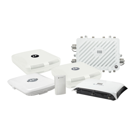
CHAPTER 1 OVERVIEW Motorola Solutions’ family of WING 5.4.2 supported access points enable high performance with secure and resilient wireless voice and data services to remote locations with the scalability required to meet the needs of large distributed enterprises. AP6511, AP6521, AP6522, AP6532, AP6562, AP7131, AP7161, AP7181, AP8132 access points and ES6510 model ethernet switch can now use WiNG 5 software as its onboard operating system. - Page 22 1 - 2 WiNG 5.4.2 Access Point System Reference Guide is optimized to prevent wired congestion and wireless congestion. Traffic flows dynamically, based on user and application, and finds alternate routes to work around network choke points. NOTE: This guide describes the installation and use of the WiNG 5 software designed specifically for AP6511, AP6521, AP6522, AP6532, AP6562, AP7131, AP7161, AP7181, AP8132 access points and ES6510 model ethernet switch.
-
Page 23: About The Motorola Solutions Wing 5 Software
Deploying a new WiNG 5 access point managed network does not require the replacement of existing Motorola Solutions access points. WiNG 5 enables the simultaneous use of existing architectures from Motorola Solutions and other vendors, even if those other architectures are centralized models. - Page 24 1 - 4 WiNG 5.4.2 Access Point System Reference Guide...
-
Page 25: Chapter 2, Web User Interface Features
CHAPTER 2 WEB USER INTERFACE FEATURES The access point’s resident user interface contains a set of features specifically designed to enable either Virtual Controller AP, Standalone AP or Adopt to Controller functionality. In Virtual Controller AP mode, an access point can manage up to 24 other access points of the same model and share data amongst managed access points. -
Page 26: Accessing The Web Ui
1 GB of RAM for the UI to display and function properly. The Web UI is based on Flex, and does not use Java as the underlying UI framework. Motorola Solutions recommends using a resolution of 1280 x 1024 pixels for using the GUI. - Page 27 2 - 3 Figure 2-1 Access Point Web UI Login Screen 9. Enter the default username admin in the Username field. 10. Enter the default password motorola in the Password field. 11. Select the Login button to load the management interface.
-
Page 28: Icon Glossary
2 - 4 WiNG 5.4.2 Access Point System Reference Guide 2.2 Icon Glossary The access point interface utilizes a number of icons designed to interact with the system, gather information from managed devices and obtain status. This chapter is a compendium of the icons used, and is organized as follows: •... -
Page 29: Dialog Box Icons
2 - 5 Create new policy – Select this icon to create a new policy. Policies define different configuration parameters that can be applied to device configurations, and device profiles. Edit policy – Select this icon to edit an existing policy. To edit a policy, click on the policy and select this button. -
Page 30: Status Icons
2 - 6 WiNG 5.4.2 Access Point System Reference Guide 2.2.4 Status Icons Icon Glossary These icons define device status, operations on the wireless controller, or any other action that requires a status being returned to the user. Fatal Error – States there is an error causing a managed device to stop functioning. - Page 31 2 - 7 Radio QoS Policy – Indicates a QoS policy configuration has been impacted. AAA Policy – Indicates an Authentication, Authorization and Accounting (AAA) policy has been impacted. AAA policies define RADIUS authentication and accounting parameters. Association ACL – Indicates an Association Access Control List (ACL) configuration has been impacted.
- Page 32 2 - 8 WiNG 5.4.2 Access Point System Reference Guide Advanced WIPS Policy – States the conditions of an advanced WIPS policy have been invoked. WIPS prevents unauthorized access to the system by checking for and removing rogue access point’s and wireless clients.
-
Page 33: Configuration Objects
2 - 9 2.2.6 Configuration Objects Icon Glossary Configuration icons are used to define the following: Configuration – Indicates an item capable of being configured by the access point’s interface. View Events / Event History – Defines a list of events. Select this icon to view events or view the event history. -
Page 34: Access Type Icons
2 - 10 WiNG 5.4.2 Access Point System Reference Guide 2.2.8 Access Type Icons Icon Glossary The following icons display a user access type: Web UI – Defines a Web UI access permission. A user with this permission is permitted to access an associated device’s Web UI. -
Page 35: Device Icons
2 - 11 Help Desk – Indicates help desk privileges. A help desk user is allowed to use troubleshooting tools like sniffers, execute service commands, view or retrieve logs and reboot an access point. Web User – Indicates a Web user privilege. A Web user is allowed accessing the access point’s Web user interface. - Page 36 2 - 12 WiNG 5.4.2 Access Point System Reference Guide...
-
Page 37: Chapter 3, Quick Start
CHAPTER 3 QUICK START Access Points can utilize an initial setup wizard to streamline the process of initially accessing the wireless network. The wizard defines the access point’s operational mode, deployment location, basic security, network and WLAN settings. For instructions on how to use the initial setup wizard, see Using the Initial Setup Wizard on page 3-2. -
Page 38: Using The Initial Setup Wizard
3 - 2 WiNG 5.4.2 Access Point System Reference Guide 3.1 Using the Initial Setup Wizard Quick Start Once the access point is installed and powered on, complete the following steps to get the access point up and running and access management functions: 1. - Page 39 3 - 3 Figure 3-2 Initial Setup Wizard NOTE: The Initial Setup Wizard displays the same pages and content for each access point model supported. The only difference being the number of radios configurable by model, as an AP7131 model can support up to three radios, AP6522, AP6532, AP6562, AP8132 and AP7161 models support two radios and AP6511 and AP6521 models support a single radio.
- Page 40 3 - 4 WiNG 5.4.2 Access Point System Reference Guide The first page of the Initial Setup Wizard displays the Navigation Panel Introduction for the configuration activities comprising the access point's initial setup. A green check mark to the left of an item in the...
- Page 41 Standalone Mode. NOTE: If designating the access point as a Standalone AP, Motorola Solutions recommends the access point’s UI be used exclusively to define its device configuration, and not the CLI. The CLI provides the ability to define more than one profile and the UI does not.
-
Page 42: Virtual Controller Ap Mode
3 - 6 WiNG 5.4.2 Access Point System Reference Guide reboot. For more information on configuring the access point in the Adopted to Controller mode, see section Adopt to a controller. 9. Select the Next button to start configuring the access point in the selected mode. - Page 43 3 - 7 Figure 3-6 Initial Setup Wizard - Access Point Mode screen 3. Select an Access Point Mode from the available options. • Router Mode - In Router Mode, the access point routes traffic between the local network (LAN) and the Internet or external network (WAN).
- Page 44 3 - 8 WiNG 5.4.2 Access Point System Reference Guide Figure 3-7 Initial Setup Wizard - LAN Configuration screen 5. Set the following DHCP and Static IP Address/Subnet information for the LAN interface: • Use DHCP - Select the checkbox to enable an automatic network address configuration using the access points DHCP server.
- Page 45 3 - 9 request for a domain name is made but the DNS server, responsible for converting the name into its corresponding IP address, cannot locate the matching IP address. • Primary DNS - Enter an IP Address for the main Domain Name Server providing DNS services for the access point's LAN interface.
- Page 46 3 - 10 WiNG 5.4.2 Access Point System Reference Guide available ports differ depending on the access point model deployed. Access point models with a single port have this option selected and disabled. • Enable NAT on the WAN Interface - Select the checkbox to allow traffic to pass between the access point's WAN and LAN interfaces.
- Page 47 3 - 11 Radio. The selected band is used for WLAN client support. Consider selecting one radio for 2.4 GHz and another for 5.0 GHz support (if using a dual or three radio model) when supporting clients in both the 802.11bg and 802.11n bands. •...
- Page 48 3 - 12 WiNG 5.4.2 Access Point System Reference Guide Figure 3-10 Initial Setup Wizard - Wireless LAN Setting screen 11. Set the following parameters for each of the WLAN configurations available as part of this Initial Setup Wizard: •...
- Page 49 3 - 13 resource is used. • WPA Key - If a WPA key is required (PSK Authentication and WPA2 Encryption), enter an alphanumeric string of 8 to 63 ASCII characters or 64 HEX characters as the primary string both transmitting and receiving authenticators must share. The alphanumeric string allows character spaces.
- Page 50 3 - 14 WiNG 5.4.2 Access Point System Reference Guide 13. Refer to the Username Description columns in the table to review credentials of existing RADIUS Server user accounts. Add new accounts or edit the properties of existing accounts as updates are required.
- Page 51 3 - 15 Figure 3-12 Initial Setup Wizard - Country/Date/Time screen 17. Refer to the Country and Time Zone field to set the following device deployment information: • Location - Define the location of the access point. The Location parameter acts as a reminder of where the access point can be located within the managed wireless network.
- Page 52 3 - 16 WiNG 5.4.2 Access Point System Reference Guide 19. Select Next. The Initial Setup Wizard displays the Summary and Commit screen to summarize the screens (pages) and settings updated using the Initial AP Setup Wizard. There is no user intervention or additional settings required within this screen. It is an additional means of validating the configuration before it is deployed.
-
Page 53: Adopt To A Controller
3 - 17 3.1.3 Adopt to a controller Using the Initial Setup Wizard Adopted to Controller is the default behavior of the access point. When the access point is switched on for the first time, it looks for a wireless controller on the default subnet and that runs the same WiNG firmware version and automatically adopts to it. - Page 54 3 - 18 WiNG 5.4.2 Access Point System Reference Guide...
-
Page 55: Chapter 4, Dashboard
CHAPTER 4 DASHBOARD The dashboard allows network administrators to review and troubleshoot the operation of the devices comprising the access point managed network. Use the dashboard to review the current network topology, assess the network’s component health and diagnose problematic device behavior. By default, the Dashboard screen displays the System Dashboard, which is the top level in the device hierarchy. -
Page 56: Dashboard Conventions
4 - 2 WiNG 5.4.2 Access Point System Reference Guide 4.1 Dashboard Dashboard The Dashboard screen displays device information organized by device association and inter-connectivity between an access point and connected wireless clients. To review dashboard information: 1. Select Dashboard. Expand the... -
Page 57: Health
4 - 3 4.1.1.1 Health Dashboard Conventions Health tab displays information about the state of the access point managed network. Figure 4-2 Dashboard - Health tab Information in the Health tab is classified as: • Device Details • Radio RF Quality Index •... - Page 58 4 - 4 WiNG 5.4.2 Access Point System Reference Guide Figure 4-3 Dashboard - Health tab - Device Details field Device Details field displays the name assigned to the selected access point, its factory encoded MAC address, its primary IP address, model type, RF Domain, software version, uptime, CPU and RAM information and system clock. Use this data to determine whether a software upgrade is warranted, or if the system clock needs adjustment.
- Page 59 4 - 5 Periodically select Refresh (at the bottom of the screen) to update the RF quality data. 4.1.1.1.3 Radio Utilization Index Dashboard Conventions Radio Utilization Index field displays how efficiently the RF medium is used by the access point. Traffic utilization is defined as the percentage of throughput relative to the maximum possible throughput.
-
Page 60: Inventory
4 - 6 WiNG 5.4.2 Access Point System Reference Guide 1. The Client RF Quality Index field displays the following: Worst 5 Lists the worst 5 performing client radios connected to the access point. The RF Quality Index measures the overall effectiveness of the RF environment as a percentage. Its a function of the connect rate in both directions, as well as the retry rate and the error rate. - Page 61 4 - 7 Figure 4-7 Dashboard - Inventory tab The Inventory tab is partitioned into the following fields: • Radio Types • WLAN Utilization • Wireless Clients • Clients by Radio Type 4.1.1.2.5 Radio Types Inventory Radio Types field displays the total number and types of radios managed by the selected access point. Figure 4-8 Dashboard - Inventory tab - Radio Types field...
- Page 62 4 - 8 WiNG 5.4.2 Access Point System Reference Guide Refer to the Total Radios column to review the number of managed radios. Additionally, use the charts on the bottom of the Radio Types field to assess the number WLANs utilized in supported radio bands.
- Page 63 4 - 9 Use this information to assess if an access point managed radio is optimally deployed in respect to its radio type and intended client support requirements. NOTE: AP6522, AP6532, AP6562, AP8132, AP7131, AP7161 and AP7181 model access points can support up to 256 client connections to a single access point. AP6511 and AP6521 model access points (both single radio models) can support up to 128 client connections per access point.
-
Page 64: Network View
4 - 10 WiNG 5.4.2 Access Point System Reference Guide 4.2 Network View Dashboard Network View screen displays device topology association between a selected access point, its RF Domain and its connected clients. The association is displayed using a number of different color options. -
Page 65: Network View Display Options
4 - 11 Figure 4-13 Network View - System Browser 4.2.1 Network View Display Options Network View 1. Select the blue Options link right under the Network View banner to display a menu for different device interaction display options. Figure 4-14 Network View - Display Options 2. -
Page 66: Device Specific Information
4 - 12 WiNG 5.4.2 Access Point System Reference Guide and error rates. Quality results include: Red (Bad Quality), Orange (Poor Quality), Yellow (Fair Quality) and Green (Good Quality). • Vendor – Displays the device manufacturer. • Band – Select this option to filter based on the 2.4 or 5.0 GHz radio band of connected clients. Results include: Yellow (2.4 GHz radio band) and Blue (5.0 GHz radio band). -
Page 67: Chapter 5, Device Configuration
CHAPTER 5 DEVICE CONFIGURATION Access points can either be assigned unique configurations to support a particular deployment objective or have an existing RF Domain or Profile configuration modified (overridden) to support a requirement that deviates its configuration from the configuration shared by its peer access points. Refer to the following to set an access point’s sensor functionality, Virtual Controller AP designation, and license and certificate usage configuration: •... -
Page 68: Rf Domain Configuration
5 - 2 WiNG 5.4.2 Access Point System Reference Guide 5.1 RF Domain Configuration Device Configuration An access point’s configuration is composed of numerous elements including a RF Domain, WLAN and device specific settings. RF Domains are used to assign regulatory, location and relevant policies to access points of the same model. For example, an AP6532 RF Domain can only be applied to another AP6532 model. -
Page 69: Rf Domain Sensor Configuration
In addition to dedicated Motorola Solutions AirDefense sensors, an access point radio can function as a sensor and upload information to a dedicated WIPS server (external to the access point). Unique WIPS server configurations can be used to ensure... - Page 70 5 - 4 WiNG 5.4.2 Access Point System Reference Guide WIPS is not supported on a WLAN basis, rather, sensor functionality is supported on the access point radio(s) available to each managed WLAN. When an access point radio is functioning as a WIPS sensor, it is able to scan in sensor mode across all legal channels within the 2.4 and 5.0 GHz band.
-
Page 71: System Profile Configuration
5 - 5 5.2 System Profile Configuration Device Configuration An access point profile enables an administrator to assign a common set of configuration parameters and policies to the access point of the same model. Profiles can be used to assign common or unique network, wireless and security parameters to across a large, multi segment, site. -
Page 72: General Profile Configuration
5 - 6 WiNG 5.4.2 Access Point System Reference Guide 5.2.1 General Profile Configuration System Profile Configuration An access point profile requires unique clock synchronization settings as part of its general configuration. Network Time Protocol (NTP) manages time and/or network clock synchronization within the access point managed network. -
Page 73: Profile Radio Power
5 - 7 Server IP Set the IP address of each server added as a potential NTP resource. Version Use the spinner control to specify the version number used by this NTP server resource. The default setting is 0. 5. Use the RF Domain Manager field to configure how this access point behaves in standalone mode. - Page 74 5 - 8 WiNG 5.4.2 Access Point System Reference Guide Figure 5-4 Profile - Power screen 5. Use the Power Mode drop-down menu to set the Power Mode Configuration on this NOTE: Single radio model access points always operate using a full power configuration.
-
Page 75: Profile Adoption (Auto Provisioning) Configuration
5 - 9 5.2.3 Profile Adoption (Auto Provisioning) Configuration System Profile Configuration Adoption is the process an access point uses to discover Virtual Controller APs available in the network, pick the most desirable Virtual Controller, establish an association with the and optionally obtain an image upgrade, obtains its configuration and considers itself provisioned. - Page 76 5 - 10 WiNG 5.4.2 Access Point System Reference Guide Figure 5-5 Profile Adoption screen 5. Define the Preferred Group used as optimal group of Virtual Controller for adoption. The name of the preferred group cannot exceed 64 characters. 6. Define the Hello Interval value in seconds.
-
Page 77: Profile Interface Configuration
5 - 11 Routing Level Use the spinner controller to set the routing level for the Virtual Controller link. The default setting is 1. IPSec Support Select to enable secure communication between the access point and the wireless controllers. IPSec GW Use the drop-down menu to specify if the IPSec Gateway resource is defined as a (non DNS) IP Address or a Hostname. -
Page 78: Ethernet Port Configuration
5 - 12 WiNG 5.4.2 Access Point System Reference Guide 5.2.4.1 Ethernet Port Configuration Profile Interface Configuration Displays the physical port name reporting runtime data and statistics. The following ports are available depending on model: • AP6511 - fe1, fe2, fe3, fe4, up1 •... - Page 79 5 - 13 Admin Status A green check mark defines the port as active and currently enabled with the profile. A red “X” defines the port as currently disabled and not available for use. The interface status can be modified with the port configuration as required. Mode Displays the profile’s current switching mode as either Access or Trunk.
- Page 80 5 - 14 WiNG 5.4.2 Access Point System Reference Guide 7. Set the following Ethernet port Properties: Description Enter a brief description for the port (64 characters maximum). The description should reflect the port’s intended function to differentiate it from others with similar configurations.
- Page 81 5 - 15 Tag Native VLAN Select this option to tag the native VLAN. The IEEE 802.1Q specification is supported for tagging frames and coordinating VLANs between devices. IEEE 802.1Q adds four bytes to each frame identifying the VLAN ID for upstream devices that the frame belongs. If the upstream Ethernet device does not support IEEE 802.1Q tagging, it does not interpret the tagged frames.
- Page 82 5 - 16 WiNG 5.4.2 Access Point System Reference Guide 14. If a firewall rule does not exist suiting the data protection needs of the target port configuration, select the Create icon to define a new rule configuration. 15. Refer to the...
- Page 83 5 - 17 Quiet Period Configures the duration in seconds where no attempt is made to reauthenticate a controlled port. Set a value from 0 - 65535 seconds. Reauthentication Period Configures the duration after which a controlled port is forced to reauthenticate. Set a value from 0 - 65535 seconds.
- Page 84 5 - 18 WiNG 5.4.2 Access Point System Reference Guide Figure 5-9 Ethernet Ports - Spanning Tree tab 19. Refer to the PortFast field to define the following: Enable PortFast PortFast reduces the time taken for a port to complete STP. PortFast must only be enabled on ports on the wireless controller which are directly connected to a Server/ Workstation and not to another hub or controller.
- Page 85 5 - 19 Cisco MSTP Select to enable or disable interoperability with CISCO’s implementation of MSTP Interoperability which is incompatible with standard MSTP. Force Protocol Version Select the STP protocol to use with this port. Select Not Supported to disable STP on this port.
-
Page 86: Virtual Interface Configuration
5 - 20 WiNG 5.4.2 Access Point System Reference Guide 5.2.4.2 Virtual Interface Configuration Profile Interface Configuration A Virtual Interface is required for layer 3 (IP) access to provide layer 3 service on a VLAN. The Virtual Interface defines which IP address is associated with each VLAN ID the access point is connected to. - Page 87 5 - 21 Admin Status A green check mark defines the listed Virtual Interface configuration as active and enabled with its supported profile. A red “X” defines the Virtual Interface as currently disabled. The interface status can be modified when a new Virtual Interface is created or an existing one modified.
- Page 88 5 - 22 WiNG 5.4.2 Access Point System Reference Guide 9. Set the following network information from within the IP Addresses field: Enable Zero The access point can use Zero Config for IP assignments on an individual virtual interface Configuration basis.
- Page 89 5 - 23 Figure 5-12 Virtual Interfaces - Security tab 13. Use the Inbound IP Firewall Rules drop-down menu to select the firewall rule configuration to apply to this Virtual Interface. The firewall inspects and packet traffic to and from connected clients. If a firewall rule does not exist suiting the data protection needs of this Virtual Interface, select the Create icon to define a new firewall rule configuration or the Edit icon to modify an existing configuration.
-
Page 90: Port Channel Configuration
5 - 24 WiNG 5.4.2 Access Point System Reference Guide 5.2.4.3 Port Channel Configuration Profile Interface Configuration The access point’s profile can be applied customized port channel configurations as part of its Interface configuration. To define a port channel configuration for an access point profile: Figure 5-13 Profile Interfaces - Port Channels screen 1. - Page 91 5 - 25 Figure 5-14 Port Channels - Basic Configuration tab 7. Set the following port channel Properties: Description Enter a brief description for the port channel (64 characters maximum). The description should reflect the port channel’s intended function. Admin Status Select the Enabled radio button to define this port channel as active to the controller profile it supports.
- Page 92 5 - 26 WiNG 5.4.2 Access Point System Reference Guide 8. Use the Port Channel Load Balance drop-down menu within the Client Load Balancing field to define whether port channel load balancing is conducted using a Source/Destination IP or a Source/Destination MAC as criteria. Source/ Destination IP is the default setting.
- Page 93 5 - 27 Figure 5-15 Port Channels - Security tab 12. Refer to the Access Control field. As part of the port channel’s security configuration, Inbound IP and MAC address firewall rules are required. Use the Inbound IP Firewall Rules Inbound MAC Firewall Rules drop-down menus to select firewall rules to apply to this profile’s port channel configuration.
- Page 94 5 - 28 WiNG 5.4.2 Access Point System Reference Guide 14. Select to save the changes to the security configuration. Select Reset to revert to the last saved configuration. 15. Select the Spanning Tree tab. Figure 5-16 Port Channels - Spanning Tree tab 16.
- Page 95 5 - 29 Link Type Select either the Point-to-Point or Shared radio button. Selecting Point-to-Point indicates the port should be treated as connected to a point-to-point link. Selecting Shared means this port should be treated as having a shared connection. A port connected to a hub is on a shared link, while one connected to a access point is a point- to-point link.
-
Page 96: Access Point Radio Configuration
5 - 30 WiNG 5.4.2 Access Point System Reference Guide 5.2.4.4 Access Point Radio Configuration Profile Interface Configuration An access point profile can have its radio configuration modified once its radios have successfully associated to the network. To define a access point radio configuration: 1. - Page 97 5 - 31 Channel Lists the channel setting for the radio. Smart is the default setting. If set to Smart, the access point scans non-overlapping channels listening for beacons from other access points. After the channels are scanned, it selects the channel with the fewest access points.
- Page 98 Motorola Solutions recommends that only a professional installer set the antenna gain. The default value is 0.00.
- Page 99 5 - 33 Antenna Mode Set the number of transmit and receive antennas on the access point. 1x1 is used for transmissions over just the single “A” antenna. 2x2 is used for transmissions and receipts over two antennas for dual antenna models. 1xAll is used when transmission occurs on one antenna and is received on all receiving antennas.
- Page 100 5 - 34 WiNG 5.4.2 Access Point System Reference Guide 10. Set the following profile WLAN Properties for the selected access point radio. Beacon Interval Set the interval between radio beacons in milliseconds (either 50, 100 or 200). A beacon is a packet broadcast by adopted radios to keep the network synchronized.
- Page 101 5 - 35 Guard Interval Use the drop-down menu to specify a Long or Any guard interval. The guard interval is the space between symbols (characters) being transmitted. The guard interval is there to eliminate inter-symbol interference (ISI). ISI occurs when echoes or reflections from one symbol interfere with another symbol.
- Page 102 5 - 36 WiNG 5.4.2 Access Point System Reference Guide Figure 5-19 Access Point Radio - WLAN Mapping tab 16. Refer to the WLAN Mapping/Mesh Mapping field to set WLAN BSSID assignments for an existing access point deployment. Administrators can assign each WLAN its own BSSID. If using a single-radio access point, there are 8 BSSIDs available. If using a dual-radio access point there are 8 BSSIDs for the 802.11b/g/n radio and 8 BSSIDs for the 802.11a/n radio.
- Page 103 5 - 37 Figure 5-20 Access Point Radio - Mesh Legacy tab Use the Mesh Legacy screen to define how mesh connections are established and the number of links available amongst access points within the Mesh network. 22. Define the following Mesh Settings: Mesh Options include Client, Portal and Disabled.
- Page 104 5 - 38 WiNG 5.4.2 Access Point System Reference Guide Figure 5-21 Access Point Radio - Advanced Settings tab 26. Refer to the Aggregate MAC Protocol Data Unit (A-MPDU) field to define how MAC service frames are aggregated by the access point radio.
- Page 105 5 - 39 29. Set the following Non-Unicast Traffic values for the profile’s supported access point radio and its connected wireless clients: Broadcast/Multicast Use the Select drop-down menu to launch a sub screen to define the data rate broadcast Transmit Rate and multicast frames are transmitted.
-
Page 106: Pppoe Configuration
5 - 40 WiNG 5.4.2 Access Point System Reference Guide 5.2.4.5 PPPoE Configuration Profile Interface Configuration PPP over Ethernet (PPPoE) is a data-link protocol for dialup connections. PPPoE allows the access point to use a broadband modem (DSL, cable modem, etc.) for access to high-speed data and broadband networks. Most DSL providers are currently supporting (or deploying) the PPPoE protocol. - Page 107 5 - 41 Figure 5-22 Profile Interface - PPPoE screen 5. Use the Basic Settings field to enable PPPoE and define a PPPoE client. Enable PPPoE Select Enable to support a high speed client mode point-to-point connection using the PPPoE protocol. The default setting is disabled. Service Enter the 128 character maximum PPPoE client service name provided by the service provider.
- Page 108 5 - 42 WiNG 5.4.2 Access Point System Reference Guide 6. Define the following Authentication parameters for PPPoE client interoperation: Username Provide the 64 character maximum username used for authentication support by the PPPoE client. Password Provide the 64 character maximum password used for authentication by the PPPoE client.
-
Page 109: Wan Backhaul Configuration
5 - 43 5.2.4.6 WAN Backhaul Configuration Profile Interface Configuration A Wireless Wide Area Network (WWAN) card is a specialized network interface card that allows a network device to connect, transmit and receive data over a Cellular Wide Area Network. The AP7131N model access point has a PCI Express card slot that supports 3G WWAN cards. - Page 110 5 - 44 WiNG 5.4.2 Access Point System Reference Guide Figure 5-23 Profile Interface - WAN Backhaul screen 5. Refer to the WAN (3G) Backhaul configuration to specify the access point’s WAN card interface settings: WAN Interface Name Displays the WAN Interface name for the WAN 3G Backhaul card.
- Page 111 5 - 45 8. Configure the Inbound IP Firewall Rules. Use the drop-down menu to select a firewall (set of IP access connection rules) to apply to the PPPoE client connection. If a firewall rule does not exist suiting the data protection needs of the PPPoE client connection, select the Create icon to define a new rule configuration or the Edit icon to modify an existing rule.
-
Page 112: Profile Network Configuration
5 - 46 WiNG 5.4.2 Access Point System Reference Guide 5.2.5 Profile Network Configuration System Profile Configuration Setting an access point profile’s network configuration is a large task comprised of numerous administration activities. An access point profile network configuration process consists of the following: •... -
Page 113: Dns Configuration
5 - 47 5.2.5.1 DNS Configuration Profile Network Configuration Domain Naming System (DNS) is a hierarchical naming system for resources connected to the Internet or a private network. Primarily, DNS resources translate domain names into IP addresses. If one DNS server does not know how to translate a particular domain name, it asks another one until the correct IP address is returned. -
Page 114: Arp
5 - 48 WiNG 5.4.2 Access Point System Reference Guide 8. Select to save the changes made to the DNS configuration. Select Reset to revert to the last saved configuration. 5.2.5.2 ARP Profile Network Configuration Address Resolution Protocol (ARP) is a protocol for mapping an IP address to a hardware MAC address recognized on the network. - Page 115 5 - 49 Device Type Specify the device type the ARP entry supports (Host, Router or DHCP Server). Host is the default setting. 7. Select the button located at the bottom right of the screen to save the changes to the ARP configuration. Select Reset to revert to the last saved configuration.
-
Page 116: L2Tpv3 Profile Configuration
5 - 50 WiNG 5.4.2 Access Point System Reference Guide 5.2.5.3 L2TPv3 Profile Configuration Profile Network Configuration L2TP V3 is an IETF standard used for transporting different types of layer 2 frames in an IP network (and access point profile). - Page 117 5 - 51 Figure 5-26 Network - L2TPv3 screen - General tab 5. Set the following General Settings for an L2TPv3 profile configuration: Host Name Define a 64 character maximum host name to specify the name of the host that’s sent tunnel messages.
- Page 118 5 - 52 WiNG 5.4.2 Access Point System Reference Guide Figure 5-27 Network - L2TPv3 screen - T2TP tunnel tab 7. Review the following L2TPv3 tunnel configuration data: Name Displays the name of each listed L2TPv3 tunnel assigned upon creation.
- Page 119 5 - 53 Figure 5-28 Network - L2TPv3 screen - Add T2TP Tunnel Configuration 9. If creating a new tunnel configuration, assign it a 31 character maximum Name. 10. Define the following Settings required for the L2TP tunnel configuration: Local IP Address Enter the IP address assigned as the local tunnel end point address, not the interface IP address.
- Page 120 5 - 54 WiNG 5.4.2 Access Point System Reference Guide Use Tunnel Policy Select the L2TPv3 tunnel policy. The policy consists of user defined values for protocol specific parameters which can be used with different tunnels. If none is available a new policy can be created or an existing one can be modified.
- Page 121 5 - 55 Figure 5-29 Network - L2TPv3 screen - Add T2TP Peer Configuration 12. Define the following Peer parameters: Peer ID Define the primary peer ID used to set the primary and secondary peer for tunnel failover. If the peer is not specified, tunnel establishment does not occur. However, if a peer tries to establish a tunnel with this access point, it creates the tunnel if the hostname and/or Router ID matches.
- Page 122 5 - 56 WiNG 5.4.2 Access Point System Reference Guide Pseudowire ID Define a psuedowire ID for this session. A pseudowire is an emulation of a layer 2 point-to-point connection over a packet-switching network (PSN). A pseudowire was developed out of the necessity to encapsulate and tunnel layer 2 protocols across a layer 3 network.
- Page 123 5 - 57 Local Session ID Displays the numeric identifier assigned to each listed tunnel session. This is the pseudowire ID for the session. This pseudowire ID is sent in a session establishment message to the L2TP peer. Displays each sessions’s maximum transmission unit (MTU). The MTU is the size (in bytes) of the largest protocol data unit the layer can pass between tunnel peers in this session.
- Page 124 5 - 58 WiNG 5.4.2 Access Point System Reference Guide IP Address Specify the IP address used to be as tunnel source ip address. If not specified, the tunnel source IP address is selected automatically based on the tunnel peer IP address. This address is applicable only for initiating the tunnel.
-
Page 125: Igmp Snooping
5 - 59 5.2.5.4 IGMP Snooping Profile Network Configuration Internet Group Management Protocol (IGMP) is a protocol to establish and maintain multicast group memberships to interested members. Multicasting allows a networked computer to send content to multiple computers who have registered to receive the content. - Page 126 5 - 60 WiNG 5.4.2 Access Point System Reference Guide 6. Set the following for IGMP Querier configuration: Enable IGMP Querier Select this option to enable IGMP querier. IGMP snoop querier is used to keep host memberships alive. It is primarily used in a network where there is a multicast streaming server and hosts subscribed to the server and no IGMP querier present.
-
Page 127: Quality Of Service (Qos)
5 - 61 5.2.5.5 Quality of Service (QoS) Profile Network Configuration The uses different Quality of Service (QoS) screens to define WLAN and device radio QoS configurations. The System Profiles > Network > QoS facility is separate from WLAN and radio QoS configurations, and is used to configure the priority of the different DSCP packet types. - Page 128 5 - 62 WiNG 5.4.2 Access Point System Reference Guide 802.1p Priority Assign a 802.1p priority as a 3-bit IP precedence value in the Type of Service field of the IP header used to set the priority. The valid values for this field are 0-7. Up to 64 entries are permitted.
-
Page 129: Spanning Tree Configuration
5 - 63 5.2.5.6 Spanning Tree Configuration Profile Network Configuration The Multiple Spanning Tree Protocol (MSTP) provides an extension to RSTP to optimize the usefulness of VLANs. MSTP allows for a separate spanning tree for each VLAN group, and blocks all but one of the possible alternate paths within each spanning tree topology. - Page 130 5 - 64 WiNG 5.4.2 Access Point System Reference Guide Figure 5-34 Network - Spanning Tree screen 5. Set the following MSTP Configuration parameters: MSTP Enable Select this option to enable MSTP for this profile. MSTP is disabled by default, so enable this setting if requiring different (groups) of VLANs with the profile supported network segment.
- Page 131 5 - 65 Hello Time Set a BPDU hello interval from 1 - 10 seconds. BPDUs are exchanged regularly (every 2 seconds by default) and enable supported devices to keep track of network changes and start/stop port forwarding as required. Forward Delay Set the forward delay time from 4 - 30 seconds.
-
Page 132: Routing
5 - 66 WiNG 5.4.2 Access Point System Reference Guide 5.2.5.7 Routing Profile Network Configuration Routing is the process of selecting IP paths in a network to send access point managed network traffic. Use the Routing screen to set Destination IP and Gateway addresses enabling assignment of static IP addresses for requesting clients without creating numerous host pools with manual bindings. - Page 133 5 - 67 6. Select the Policy Based Routing policy to apply to this profile. Select the Create icon to create a policy based route or select the Edit icon to edit an existing policy after selecting it in the drop-down list. 7.
-
Page 134: Dynamic Routing (Ospf)
5 - 68 WiNG 5.4.2 Access Point System Reference Guide 5.2.5.8 Dynamic Routing (OSPF) Profile Network Configuration Open Shortest Path First (OSPF) is a link-state interior gateway protocol (IGP). OSPF routes IP packets within a single routing domain (autonomous system), like an enterprise LAN. OSPF gathers link state information from neighbor routers and constructs a network topology. - Page 135 5 - 69 Figure 5-36 Network - OSPF Settings tab 5. Enable/disable OSPF and provide the following dynamic routing settings: Enable OSPF Select this option to enable OSPF for this access point. OSPF is disabled by default. Router ID Select this option to define a router ID (numeric IP address) for this access point. This ID must be established in every OSPF instance.
- Page 136 5 - 70 WiNG 5.4.2 Access Point System Reference Guide VRRP State Check Select this option to enable checking VRRP state. If the interface’s VRRP state is not Backup, then the interface is published via OSPF. 6. Set the following...
- Page 137 5 - 71 Figure 5-37 Network - Area Settings tab 12. Review existing Area Settings configurations using: Area ID Displays either the IP address or integer representing the OSPF area. Authentication Type Lists the authentication schemes used to validate the credentials of dynamic route connections.
- Page 138 5 - 72 WiNG 5.4.2 Access Point System Reference Guide 14. Set the OSPF Area configuration. Area ID Use the drop-down menu and specify either an IP address or Integer for the OSPF area. Authentication Type Select either None, simple-password or message-digest as credential validation scheme used with the OSPF dynamic route.
- Page 139 5 - 73 18. Select the button to define a new set of virtual interface basic settings, or Edit to update the settings of an existing virtual interface configuration. Figure 5-40 Network - OSPF Virtual Interfaces - Basic Configuration tab 19.
- Page 140 5 - 74 WiNG 5.4.2 Access Point System Reference Guide Figure 5-41 Network - OSPF Virtual Interface - Security tab 26. Use the Inbound IP Firewall Rules drop-down menu to select the IP access and deny rules to apply to the OSPF dynamic route.
-
Page 141: Forwarding Database
5 - 75 5.2.5.9 Forwarding Database Profile Network Configuration A Forwarding Database is used by a bridge to forward or filter packets. The bridge reads the packet’s destination MAC address and decides to either forward the packet or drop (filter) it. If it is determined the destination MAC is on a different network segment, it forwards the packet to the segment. - Page 142 5 - 76 WiNG 5.4.2 Access Point System Reference Guide 8. Define the target VLAN ID if the destination MAC is on a different network segment. 9. Provide an Interface Name used as the target destination interface for the target MAC address.
-
Page 143: Bridge Vlan
5 - 77 5.2.5.10 Bridge VLAN Profile Network Configuration A Virtual LAN (VLAN) is separately administrated virtual network within the same physical managed network. VLANs are broadcast domains to allow control of broadcast, multicast, unicast and unknown unicast within a Layer 2 device. For example, say several computers are used in conference room X and some in conference Y. - Page 144 5 - 78 WiNG 5.4.2 Access Point System Reference Guide Edge VLAN Mode Defines whether the VLAN is currently in edge VLAN mode. An edge VLAN is the VLAN where hosts are connected. For example, if VLAN 10 is defined with wireless clients and VLAN 20 is where the default gateway resides, VLAN 10 should be marked as an edge VLAN and VLAN 20 shouldn’t be marked as an edge VLAN.
- Page 145 5 - 79 8. Firewalls, generally, are configured for all interfaces on a device. When configured, firewalls generate a large amount of flow tables that store information on the traffic that is allowed to traverse through the firewall. These flow tables occupy a large portion of the limited memory on the device that could be used for other critical purposes.
-
Page 146: Cisco Discovery Protocol Configuration
5 - 80 WiNG 5.4.2 Access Point System Reference Guide 5.2.5.11 Cisco Discovery Protocol Configuration Profile Network Configuration The Cisco Discovery Protocol (CDP) is a proprietary Data Link Layer protocol implemented in Cisco networking equipment. It's primarily used to obtain IP addresses of neighboring devices and discover their platform information. CDP is also used to obtain information about the interfaces the access point uses. -
Page 147: Link Layer Discovery Protocol Configuration
5 - 81 5.2.5.12 Link Layer Discovery Protocol Configuration Profile Network Configuration The Link Layer Discovery Protocol (LLDP) provides a standard way for a controller or access point to advertise information about themselves to networked neighbors and store information they discover from their peers. LLDP is neighbor discovery protocol that defines a method for network access devices using Ethernet connectivity to advertise information about them to peer devices on the same physical LAN and store information about the network. -
Page 148: Miscellaneous Network Configuration
5 - 82 WiNG 5.4.2 Access Point System Reference Guide Extended Power via MDI Select this option to include LLPD-MED extended power via MDI discovery TLV in LLDP Discovery PDUs. This setting is disabled by default. 6. Select the button to save the changes to the LLDP configuration. Select Reset to revert to the last saved configuration. -
Page 149: Profile Network Configuration And Deployment Considerations
5 - 83 5.2.5.14 Profile Network Configuration and Deployment Considerations Profile Network Configuration Before defining a profile’s network configuration, refer to the following deployment guidelines to ensure the profile configuration is optimally effective: • Administrators often need to route traffic to interoperate between different VLANs. Bridging VLANs are only for non-routable traffic, like tagged VLAN frames destined to some other device which will untag it. -
Page 150: Profile Security Configuration
5 - 84 WiNG 5.4.2 Access Point System Reference Guide 5.2.6 Profile Security Configuration System Profile Configuration An access point profile can have its own firewall policy, wireless client role policy, WEP shared key authentication and NAT policy applied. For more information, refer to the following sections: •... -
Page 151: Defining Profile Vpn Settings
5 - 85 5.2.6.1 Defining Profile VPN Settings Profile Security Configuration IPSec VPN provides a secure tunnel between two networked peer access points or controllers. Administrators can define which packets are sent within the tunnel, and how they’re protected. When a tunnelled peer sees a sensitive packet, it creates a secure tunnel and sends the packet through the tunnel to its remote peer destination. - Page 152 5 - 86 WiNG 5.4.2 Access Point System Reference Guide 6. Refer to the following to determine whether an IKE Policy requires creation, modification or removal: Name Displays the 32 character maximum name assigned to the IKE policy. DPD Keep Alive Lists each policy’s IKE keep alive message interval defined for IKE VPN tunnel dead peer...
- Page 153 5 - 87 Mode If using IKEv1, use the drop-down menu to define the IKE mode as either Main or Aggressive. IPSEC has two modes in IKEv1 for key exchanges. Aggressive mode requires 3 messages be exchanged between the IPSEC peers to setup the SA, Main requires 6 messages.
- Page 154 5 - 88 WiNG 5.4.2 Access Point System Reference Guide 11. Select either the IKEv1 IKEv2 radio button to enforce VPN key exchanges using either IKEv1 or IKEv2. 12. Refer to the following to determine whether a VPN Peer Configuration...
- Page 155 5 - 89 Figure 5-51 Profile Security - VPN Peer Configuration create/modify screen (IKEv2 example) Name If creating a new peer configuration (remote gateway) for VPN tunnel connection, assign it a name (32 character maximum) to distinguish it from others with similar attributes.
- Page 156 5 - 90 WiNG 5.4.2 Access Point System Reference Guide IKE Policy Name Select the IKEv1 or IKE v2 policy name (and settings) to apply to this peer configuration. If a policy requires creation, select the Create icon. 14. Select...
- Page 157 5 - 91 Figure 5-53 Profile Security - VPN Transform Set create/modify screen 18. Define the following settings for the new or modified Transform Set configuration: Transform Set If creating a new transform set, define a 32 character maximum name to differentiate this configuration from others with similar attributes.
- Page 158 5 - 92 WiNG 5.4.2 Access Point System Reference Guide Figure 5-54 Profile Security - VPN Crypto Map tab 21. Review the following Crypto Map configuration parameters to assess their relevance: Name Lists the 32 character maximum name assigned for each crypto map upon creation. This name cannot be modified as part of the edit process.
- Page 159 5 - 93 Figure 5-55 Profile Security - VPN Crypto Map screen 24. Review the following before determining whether to add or modify a crypto map configuration: Sequence Each crypto map configuration uses a list of entries based on a sequence number. Specifying multiple sequence numbers within the same crypto map, provides the flexibility to connect to multiple peers from the same interface, based on the sequence number (from 1 - 1,000).
- Page 160 5 - 94 WiNG 5.4.2 Access Point System Reference Guide Figure 5-56 Profile Security - VPN Crypto Map Entry screen 26. Define the following parameters to set the crypto map configuration: Sequence Each crypto map configuration uses a list of entries based on a sequence number.
- Page 161 5 - 95 IP Firewall Rules Use the drop-down menu to select the access list (ACL) used to protect IPSec VPN traffic. New access/deny rules can be defined for the crypto map by selecting the Create icon, or an existing set of firewall rules can be modified by selecting the Edit icon.
- Page 162 5 - 96 WiNG 5.4.2 Access Point System Reference Guide Figure 5-57 Profile Security - Remote VPN Server tab (IKEv2 example) 29. Select either the IKEv1 IKEv2 radio button to enforce peer key exchanges over the remote VPN server using either IKEv1 or IKEv2.
- Page 163 5 - 97 AAA Policy Select the AAA policy used with the remote VPN client. AAA policies define RADIUS authentication and accounting parameters. The access point can optionally use AAA server resources (when using RADIUS as the authentication method) to provide user database information and user authentication data.
- Page 164 5 - 98 WiNG 5.4.2 Access Point System Reference Guide Figure 5-58 Profile Security - Global VPN Settings tab 37. Refer to the following fields to define IPSec security, lifetime and authentication settings: df bit Select the DF bit handling technique used for the ESP encapsulating header. Options include clear, set and copy.
- Page 165 5 - 99 DPD Retries Use the spinner control to define the number of keep alive messages sent to an IPSec VPN client before the tunnel connection is defined as dead. The available range is from 1 - 100. The default number of messages is 5. NAT Keep Alive Define the interval (or frequency) of NAT keep alive messages for dead peer detection.
-
Page 166: Auto Ipsec Tunnel
5 - 100 WiNG 5.4.2 Access Point System Reference Guide 5.2.6.2 Auto IPSec Tunnel Profile Security Configuration IPSec tunnels are established to secure traffic, data and management traffic, from access points to remote wireless controllers. Secure tunnels must be established between access points and the wireless controller with minimum configuration pushed through DHCP option settings. -
Page 167: Defining Profile Security Settings
WEP key to access the network using this profile. The access point, other proprietary routers, and Motorola Solutions clients use the key algorithm to convert an ASCII string to the same hexadecimal number. Clients without Motorola Solutions adapters need to use WEP keys manually configured as hexadecimal numbers. -
Page 168: Setting The Certificate Revocation List (Crl) Configuration
5 - 102 WiNG 5.4.2 Access Point System Reference Guide 5.2.6.4 Setting the Certificate Revocation List (CRL) Configuration Profile Security Configuration A certificate revocation list (CRL) is a list of certificates that have been revoked or are no longer valid. A certificate can be revoked if the certificate authority (CA) had improperly issued a certificate, or if a private-key is compromised. -
Page 169: Setting The Profile's Nat Configuration
5 - 103 5.2.6.5 Setting the Profile’s NAT Configuration Profile Security Configuration Network Address Translation (NAT) is a technique to modify network address information within IP packet headers in transit across a traffic routing device. This enables mapping one IP address to another to protect network address credentials. With typical deployments, NAT is used as an IP masquerading technique to hide private IP addresses behind a single, public facing, IP address. - Page 170 5 - 104 WiNG 5.4.2 Access Point System Reference Guide NAT Pool tab displays by default. The NAT Pool tab lists those NAT policies created thus far. Any of these policies can be selected and applied to the access point profile.
- Page 171 5 - 105 Figure 5-64 Profile Security - Static NAT screen - Source tab 10. To map a source IP address from an internal network to a NAT IP address click the + Add Row button. Enter the internal network IP address in Source IP field.
- Page 172 5 - 106 WiNG 5.4.2 Access Point System Reference Guide Figure 5-65 Profile Security - Static NAT screen - Destination tab 13. Select to create a new NAT destination configuration, Edit to modify the attributes of an existing configuration or Delete to permanently remove a NAT destination.
- Page 173 5 - 107 Figure 5-66 NAT Destination - Add screen 14. Set the following Destination configuration parameters: Static NAT creates a permanent, one-to-one mapping between an address on an internal network and a perimeter or external network. To share a Web server on a perimeter interface with the Internet, use static address translation to map the actual address to a registered IP address.
- Page 174 5 - 108 WiNG 5.4.2 Access Point System Reference Guide Network Select Inside or Outside NAT as the network direction. The default setting is Inside. 15. Select to save the changes made to the static NAT configuration. Select Reset to revert to the last saved configuration.
- Page 175 5 - 109 NAT Pool Displays the name of an existing NAT pool used with the NAT configuration. Overload IP Enables the use of one global address for numerous local addresses. 18. Select to create a new Dynamic NAT configuration, Edit to modify an existing configuration or Delete...
- Page 176 5 - 110 WiNG 5.4.2 Access Point System Reference Guide Overload Type Select this option of Overload Type used with the listed IP ACL rule. Options include NAT Pool, One Global Address and Interface IP Address. Interface IP Address is the default setting.
-
Page 177: Setting The Profile's Bridge Nat Configuration
5 - 111 5.2.6.6 Setting the Profile’s Bridge NAT Configuration Profile Security Configuration Use Bridge NAT to manage Internet traffic originating at a remote site. In addition to traditional NAT functionality, Bridge NAT provides a means of configuring NAT for bridged traffic through an access point. NAT rules are applied to bridged traffic through the access point, and matching packets are NATed to the WAN link instead of being bridged on their way to the router. - Page 178 5 - 112 WiNG 5.4.2 Access Point System Reference Guide 5. Review the following Bridge NAT configurations to determine whether a new Bridge NAT configuration requires creation or an existing configuration modified or removed: Lists the ACL applying IP address access/deny permission rules to the Bridge NAT configuration.
-
Page 179: Profile Security Configuration And Deployment Considerations
5 - 113 Figure 5-71 Profile Security - Source Dynamic NAT screen - Add Row field 10. Select to save the changes made within the Add Row Dynamic NAT screens. Select Reset to revert to the last saved configuration. 5.2.6.7 Profile Security Configuration and Deployment Considerations Profile Security Configuration Before defining a profile’s security configuration, refer to the following deployment guidelines to ensure the profile configuration is optimally effective:... -
Page 180: Virtual Router Redundancy Protocol (Vrrp) Configuration
5 - 114 WiNG 5.4.2 Access Point System Reference Guide 5.2.7 Virtual Router Redundancy Protocol (VRRP) Configuration System Profile Configuration A default gateway is a critical resource for connectivity. However, it’s prone to a single point of failure. Thus, redundancy for the default gateway is required by the access point. - Page 181 5 - 115 Figure 5-72 Profiles - VRRP screen - VRRP tab 5. Review the following VRRP configuration data to assess if a new VRRP configuration is required or if an existing VRRP configuration requires modification or removal: Virtual Router ID Lists a numerical index (from 1 - 254) used to differentiate VRRP configurations.
- Page 182 5 - 116 WiNG 5.4.2 Access Point System Reference Guide Figure 5-73 Profiles - VRRP screen - Version tab VRRP version 3 (RFC 5798) and 2 (RFC 3768) are selectable to set the router redundancy. Version 3 supports sub-second (centisecond) VRRP failover and support services over virtual IP. For more information on the VRRP protocol specifications (available publicly) refer to http://www.ietf.org/rfc/rfc3768.txt...
- Page 183 5 - 117 Figure 5-74 Profiles - VRRP screen 8. If creating a new VRRP configuration, assign a Virtual Router ID from 1 - 255. In addition to functioning as numerical identifier, the ID identifies the access point’s virtual router a packet is reporting status for. 9.
- Page 184 5 - 118 WiNG 5.4.2 Access Point System Reference Guide Virtual IP Addresses Provide up to 8 IP addresses representing the Ethernet switches, routers or security appliances defined as virtual router resources to the AP7131 access point. Advertisement Interval Select either seconds, milliseconds or centiseconds as the unit used to define VRRP Unit advertisements.
-
Page 185: Profile Critical Resources
5 - 119 5.2.8 Profile Critical Resources System Profile Configuration Critical resources are device IP addresses or interface destinations on the network interoperated as critical to the health of the network. The critical resource feature allows for the continuous monitoring of these addresses. A critical resource, if not available, can result in the network suffering performance degradation. - Page 186 5 - 120 WiNG 5.4.2 Access Point System Reference Guide The screen lists the destination IP addresses or interfaces (VLAN, WWAN, or PPPoE) used for critical resource connection. IP addresses can be monitored directly by the access point or controller, whereas a VLAN, WWAN or PPPoE must be monitored behind an interface.
- Page 187 5 - 121 Mode Set the ping mode used when the availability of a critical resource is validated. Select from: • arp-only – Use the Address Resolution Protocol (ARP) for only pinging the critical resource. ARP is used to resolve hardware addresses when only the network layer address is known. •...
-
Page 188: Profile Services Configuration
5 - 122 WiNG 5.4.2 Access Point System Reference Guide 5.2.9 Profile Services Configuration System Profile Configuration A profile can contain specific guest access (captive portal) server configurations. These guest network access permissions can be defined uniquely as profile requirements dictate. -
Page 189: Profile Services Configuration And Deployment Considerations
5 - 123 Either select an existing captive portal policy, use the default captive portal policy or select the Create link to create a new captive portal configuration that can be applied to this profile. For more information, see Configuring Captive Portal Policies on page 9-2. -
Page 190: Profile Management Configuration
5 - 124 WiNG 5.4.2 Access Point System Reference Guide 5.2.10 Profile Management Configuration System Profile Configuration The access point has mechanisms to allow/deny management access to the network for separate interfaces and protocols (HTTP, HTTPS, Telnet, SSH or SNMP). These management access configurations can be applied strategically to profiles as resource permissions dictate. - Page 191 5 - 125 Figure 5-79 Profile Management - Settings screen 5. Refer to the Message Logging field to define how the profile logs system events. It’s important to log individual events to discern an overall pattern that may be negatively impacting performance using the configuration defined for the access point’s profile.
- Page 192 5 - 126 WiNG 5.4.2 Access Point System Reference Guide Remote Logging Host Use this table to define numerical (non DNS) IP addresses for up to three external resources where logged system events can be sent on behalf of the profile. Select Clear to remove an IP address.
- Page 193 5 - 127 Username for SMTP Server Specify the sender’s username on the outgoing SMTP server. Many SMTP servers require users to authenticate with a username and password before sending e-mail through the server. Password for SMTP Server Specify the sender’s username password on the outgoing SMTP server. Many SMTP servers require users to authenticate with a username and password before sending e-mail through the server.
- Page 194 5 - 128 WiNG 5.4.2 Access Point System Reference Guide 14. Use the parameters within the Automatic Adopted AP Firmware Upgrade field to define an automatic firmware configuration. Enable Controller Upgrade Select the access point model to upgrade to a newer firmware version using its of AP Firmware associated Virtual Controller AP’s most recent firmware file for that model.
-
Page 195: Upgrading Ap6532 Firmware From 5.1
3. Ping the AP6532 from the computer to ensure IP connectivity. 4. Open an SSH session on the computer and connect to the AP6532’s IP address. 5. Login with a username and password of admin/motorola. The CLI will prompt for a new password. Re-enter the password and confirm. -
Page 196: Advanced Profile Configuration
5 - 130 WiNG 5.4.2 Access Point System Reference Guide 5.2.11 Advanced Profile Configuration System Profile Configuration An access point profile’s advanced configuration is comprised of defining connected client load balance settings, a MINT protocol configuration and miscellaneous settings (NAS ID, access point LEDs and RF Domain Manager). -
Page 197: Advanced Profile Client Load Balancing
5 - 131 5.2.11.1 Advanced Profile Client Load Balancing Advanced Profile Configuration Use the screen to administer the client load across an access point’s radios. AP7131 models can have from 1-3 radios depending on the SKU. AP6522, AP6532, AP6562, AP8132, AP7131 and AP7161 models have 2 radios, while AP6511 and AP6521 models have a single radio. - Page 198 5 - 132 WiNG 5.4.2 Access Point System Reference Guide Use notifications from Select this option to use roamed client notifications in the neighbor selection process. roamed clients This feature is enabled by default, allowing access points in the neighbor selection process to consider device roaming counts as selection criteria.
- Page 199 5 - 133 2.4 GHz load at which both When the Steering Strategy is set to Steer at 2.4 GHz, use the spinner control to set bands enabled a value (from 0 - 100%) at which the load on the 5.0 GHz radio is equally preferred to this 2.4 GHz radio load.
- Page 200 5 - 134 WiNG 5.4.2 Access Point System Reference Guide Min. Value to Trigger 5GHz Use the spinner control to define a threshold (from 1 - 100) the access point uses Channel Balancing (when exceeded) to initiate channel load balancing in the 5GHz radio band. Set this value higher when wishing to keep radio traffic within their current channel designations.
-
Page 201: Configuring Mint
5 - 135 5.2.11.2 Configuring MINT Advanced Profile Configuration MINT provides the means to secure access point profile communications at the transport layer. Using MINT, an access point can be configured to only communicate with other authorized (MINT enabled) access points of the same model. Virtual Controller AP managed access points can communicate with each other exclusively over a domain. - Page 202 5 - 136 WiNG 5.4.2 Access Point System Reference Guide 3. Define the following Device Heartbeat Settings in respect to devices supported by the controller profile: Designated IS Priority Use the spinner control to set a Designated IS Priority Adjustment setting from -255 Adjustment and 255.
- Page 203 5 - 137 10. Select to create a new Link IP configuration or Edit to modify an existing MINT configuration. Figure 5-85 Advanced Profile Configuration- MINT Protocol screen - Add IP MiNT Link field 11. Set the following Link IP parameters to complete the MINT network address configuration: Define the IP address used by peer access points for interoperation when supporting the MINT protocol.
- Page 204 5 - 138 WiNG 5.4.2 Access Point System Reference Guide IPSec GW Define either an IP address or hostname for the IPSec gateway. 12. Select the VLAN tab to display the link IP VLAN information shared by the devices managed by the MINT configuration.
- Page 205 5 - 139 Figure 5-87 Advanced Profile Configuration - MINT Protocol screen - Add/edit VLAN field 14. Set the following parameters to add or modify MINT VLAN configuration: VLAN If adding a new VLAN, define a VLAN ID from 1 - 4,094 used by peers for interoperation when supporting the MINT protocol.
-
Page 206: Advanced Profile Miscellaneous Configuration
5 - 140 WiNG 5.4.2 Access Point System Reference Guide 5.2.11.3 Advanced Profile Miscellaneous Configuration Advanced Profile Configuration Refer to the advanced profile’s Miscellaneous menu item to set the profile’s NAS configuration. The profile database on the RADIUS server consists of user profiles for each connected network access server (NAS) port. Each profile is matched to a username representing a physical port. - Page 207 5 - 141 7. Set the Additional Port value for RADIUS Dynamic Authorization field. Set this value to 1700 to enable a CISCO Identity Services Engine (ISE) Authentication, Authorization and Accounting (AAA) server, when deployed in the network, to dynamically authenticate a client. When a client requests access to the network, the CISCO ISE RADIUS server presents the client with a URL where the device’s compliance to the networks security such as validity of anti-virus or anti-spyware software is checked for the validity for their definition files (this checking is called posture).
-
Page 208: Mesh Point Configuration
5 - 142 WiNG 5.4.2 Access Point System Reference Guide 5.2.12 Mesh Point Configuration System Profile Configuration The access point can be configured to be a part of a meshed network. A mesh network is one where each node in the network is be able to communicate with other nodes in the network and where the node can maintain more than one path to its peers. -
Page 209: Mesh Point Configuration
5 - 143 Preferred Neighbor Displays the MAC address of the preferred neighbor. A Preferred Neighbor is a node that this mesh point prefers to have a mesh connection with over other nodes in the mesh network. Preferred Interface Displays the name of the preferred interface. A Preferred Interface is an interface on this mesh point that is preferred over other interfaces on the device when forming a mesh network. -
Page 210: Vehicle Mounted Modem (Vmm) Deployment Consideration
From the drop-down menu, select the interface that is the preferred interface for forming a mesh network. NOTE: With this release of Motorola Solutions WiNG software, an AP7161 model access point can be deployed as a Vehicle Mounted Modem (VMM) to provide wireless network access to a mobile vehicle (car, train, etc.). -
Page 211: Managing Virtual Controllers
Virtual Controller AP of the same model. NOTE: If designating the access point as a Standalone AP, Motorola Solutions recommends the access point’s UI be used exclusively to define its device configuration, and not the CLI. - Page 212 5 - 146 WiNG 5.4.2 Access Point System Reference Guide 4. The Virtual Controller AP screen lists all peer access points within this Virtual Controller’s radio coverage area. Each listed access point is listed by its assigned System Name, MAC Address and Virtual Controller designation. Only Standalone APs of the same model can have their Virtual Controller AP designation changed.
-
Page 213: Overriding A Device Configuration
5 - 147 5.4 Overriding a Device Configuration Device Configuration Devices within the access point managed network can have an override configuration defined and applied. New devices can also have an override configuration defined and applied once NOTE: The best way to administer a network populated by numerous access points is to configure them directly from the designated Virtual Controller AP. - Page 214 5 - 148 WiNG 5.4.2 Access Point System Reference Guide Figure 5-93 Device Overrides - Basic Configuration screen 5. Set the following Configuration settings for the target device: System Name Provide the selected device a system name up to 64 characters in length. This is the device name that appears within the RF Domain or Profile the access point supports and is identified by.
-
Page 215: Certificate Management
5 - 149 5.4.2 Certificate Management Overriding a Device Configuration A certificate links identity information with a public key enclosed in the certificate. A certificate authority (CA) is a network authority that issues and manages security credentials and public keys for message encryption. - Page 216 5 - 150 WiNG 5.4.2 Access Point System Reference Guide Figure 5-94 Device Overrides - Certificates screen 6. Set the following Management Security certificate configurations: HTTPS Trustpoint Either use the default-trustpoint or select the Stored radio button to enable a drop-down menu where an existing certificate/trustpoint can be leveraged.
- Page 217 5 - 151 For more information on the certification activities, refer to the following: • Manage Certificates • RSA Key Management • Certificate Creation • Generating a Certificate Signing Request...
-
Page 218: Manage Certificates
5 - 152 WiNG 5.4.2 Access Point System Reference Guide 5.4.2.1 Manage Certificates Certificate Management If not wanting to use an existing certificate or key with a selected device, an existing stored certificate can be leveraged from a different device. Device certificates can be imported and exported to a secure remote location for archive and retrieval as required for application to other devices. - Page 219 5 - 153 Figure 5-96 Certificate Management - Import New Trustpoint screen 4. Define the following configuration parameters required for the Import of the trustpoint: Import Select the type of Trustpoint to import. The following Trustpoints can be imported: • Import – Select to import any trustpoint. •...
- Page 220 5 - 154 WiNG 5.4.2 Access Point System Reference Guide If a certificate displays within the Certificate Management screen with a CRL, that CRL can be imported. A certificate revocation list (CRL) is a list of revoked certificates, or certificates no longer valid. A certificate can be revoked if the CA improperly issued a certificate, or if a private key is compromised.
- Page 221 5 - 155 Additionally export the key to a redundant RADIUS server so it can be imported without generating a second key. If there’s more than one RADIUS authentication server, export the certificate and do not generate a second key unless you want to deploy two root certificates.
- Page 222 5 - 156 WiNG 5.4.2 Access Point System Reference Guide Protocol Select the protocol used for exporting the target trustpoint. Available options include: • tftp • ftp • sftp • http • cf • usb1 • usb2 Port If using Advanced settings, use the spinner control to set the port. This option is not valid for cf, usb1, and usb2.
- Page 223 5 - 157 Figure 5-98 Certificate Management - RSA Keys screen 3. Select a listed device to review its current RSA key configuration. Each key can have its size and character syntax displayed. Once reviewed, optionally generate a new RSA key, import a key from a selected device, export a key to a remote location or delete a key from a selected device.
- Page 224 Enter the 32 character maximum name assigned to the RSA key. Key Size Use the spinner control to set the size of the key (from 1,024 - 2,048 bits). Motorola Solutions recommends leaving this value at the default setting of 1024 to ensure optimum functionality.
- Page 225 5 - 159 Key Passphrase Define the key used by both the access point and the server (or repository) of the target RSA key. Select the Show check box to expose the actual characters used in the passphrase. Leaving the Show check box unselected displays the passphrase as a series of asterisks “*”.
- Page 226 5 - 160 WiNG 5.4.2 Access Point System Reference Guide Figure 5-101 Certificate Management - Export RSA Key screen 12. Define the following configuration parameters required to export a RSA key: Key Name Enter the 32 character maximum name assigned to the RSA key.
- Page 227 5 - 161 Host If selecting Advanced, provide the hostname of the server used to export the RSA key. This option is not valid for cf, usb1 and usb2. Path/File If selecting Advanced, specify the path to the key. Enter the complete relative path to the key on the server.
- Page 228 RSA key. Use the spinner control to set the size of the key (from 1,024 - 2,048 bits). Motorola Solutions recommends leaving this value at the default setting (1024) to ensure optimum functionality. For more information on creating a new RSA key, see...
- Page 229 5 - 163 State (ST) Enter a State for the state or province name used in the certificate. This is a required field. City (L) Enter a City to represent the city name used in the certificate. This is a required field. Organization (O) Define an Organization for the organization used in the certificate.
- Page 230 RSA key. Use the spinner control to set the size of the key (from 1,024 - 2,048 bits). Motorola Solutions recommends leaving this value at the default setting (1024) to ensure optimum functionality. For more information on creating a new RSA key, see...
-
Page 231: Rf Domain Overrides
5 - 165 Organizational Unit (OU) Enter an Organizational Unit for the name of the organization unit used in the CSR. This is a required field. Common Name (CN) If there’s a Common Name (IP address) for the organizational unit issuing the certificate, enter it here. -
Page 232: Rf Domain Overrides
5 - 166 WiNG 5.4.2 Access Point System Reference Guide Figure 5-104 Device Overrides -RF Domain Overrides screen NOTE: A blue override icon (to the left of a parameter) defines the parameter as having an override applied. To remove a device’s override, go to the Basic Configuration screen’s Device Overrides field, and then select the Clear Overrides button. -
Page 233: Profile Overrides
5 - 167 9. Select to save the changes and overrides made to the RF Domain configuration. Selecting Reset reverts the screen to its last saved configuration. 5.4.4 Profile Overrides Overriding a Device Configuration A Profile enables an administrator to assign a common set of configuration parameters and policies to another access point of the same model. - Page 234 5 - 168 WiNG 5.4.2 Access Point System Reference Guide 7. Select + Add Row below the Network Time Protocol (NTP) table to define (or override) the configurations of NTP server resources used it obtain system time. Set the following parameters to define the NTP configuration: AutoKey Select this option to enable an autokey configuration for the NTP resource.
-
Page 235: Radio Power Overrides
5 - 169 5.4.4.1 Radio Power Overrides Profile Overrides Use the Power screen to set or override one of two power modes (3af or Auto) for an access point. When Automatic is selected, the access point safely operates within available power. Once the power configuration is determined, the access point configures its operating power characteristics based on its model and power configuration. - Page 236 5 - 170 WiNG 5.4.2 Access Point System Reference Guide Figure 5-106 Profile Overrides - Power screen 7. Use the Power Mode drop-down menu to set or override the Power Mode Configuration on this AP. NOTE: Single radio model access point’s always operate using a full power configuration.
-
Page 237: Adoption Overrides
5 - 171 5.4.4.2 Adoption Overrides Profile Overrides Use the Adoption screen to define the configuration of a preferred Virtual Controller resource used for access point adoption. A Virtual Controller can adopt up to 24 access points of the same model. The Virtual Controller must also share its VLAN to peer access points wishing to adopt to it. - Page 238 5 - 172 WiNG 5.4.2 Access Point System Reference Guide Figure 5-107 Profile Overrides - Adoption screen 7. Define a 64 character maximum Preferred Group. The Preferred group is the Virtual Controller group the access point would prefer to connect upon adoption.
- Page 239 5 - 173 IPSec GW Use the drop-down menu to specify if the IPSec Gateway resource is defined as a (non DNS) IP Address or a Hostname. Once defined, provide the numerical IP or Hostname. A Hostname cannot exceed 64 characters. Force Select to enable the link to the adopting controller or the controller group to be created even when not required.
-
Page 240: Profile Interface Override Configuration
5 - 174 WiNG 5.4.2 Access Point System Reference Guide 5.4.4.3 Profile Interface Override Configuration Profile Overrides An access point requires its Virtual Interface be configured for layer 3 (IP) access or layer 3 service on a VLAN. A virtual interface defines which IP address is associated with each connected VLAN ID. - Page 241 5 - 175 Figure 5-108 Profile Overrides - Interface Ethernet Port screen 8. Refer to the following to review port status and assess whether an override is warranted: Name Displays the physical port name reporting runtime data and statistics. Supported ports vary depending the supported AP6511, AP6521, AP6522, AP6532, AP6562, AP8132, AP7131 or AP7161 model.
- Page 242 5 - 176 WiNG 5.4.2 Access Point System Reference Guide Tag Native VLAN A green check mark defines the native VLAN as tagged. A red “X” defines the native VLAN as untagged. When a frame is tagged, the 12 bit frame VLAN ID is added to the 802.1Q header so upstream Ethernet devices know which VLAN ID the frame belongs to.
- Page 243 5 - 177 Speed Set the speed at which the port can receive and transmit the data. Select either 10 Mbps, 100 Mbps, 1000 Mbps. Select either of these options to establish a 10, 100 or 1000 Mbps data transfer rate for the selected half duplex or full duplex transmission over the port. These options are not available if Auto is selected.
- Page 244 5 - 178 WiNG 5.4.2 Access Point System Reference Guide Tag Native VLAN Select this option to tag the native VLAN. The IEEE 802.1Q specification is supported for tagging frames and coordinating VLANs between devices. IEEE 802.1Q adds four bytes to each frame identifying the VLAN ID for upstream devices that the frame belongs.
- Page 245 5 - 179 16. Use the IP Inbound Firewall Rules MAC Inbound Firewall Rules drop-down menus to select the firewall rules to apply to this profile’s Ethernet port configuration. The firewall inspects IP and MAC traffic flows and detects attacks typically not visible to traditional wired firewall appliances.
- Page 246 5 - 180 WiNG 5.4.2 Access Point System Reference Guide Maximum Request Set the number of times an attempt is made to authenticate with an EAP server before returning an ‘Authentication Failed’ message to the device seeking to authenticate itself using the controlled port.
- Page 247 5 - 181 Multiple Spanning Tree Protocol (MSTP) provides an extension to RSTP to optimize the usefulness of VLANs. MSTOP allows for a separate spanning tree for each VLAN group, and blocks all but one of the possible alternate paths within each spanning tree topology.
- Page 248 5 - 182 WiNG 5.4.2 Access Point System Reference Guide network segment. The cost of a path is the sum of all costs of traversal from the source to the destination. The default rule for the cost of a network segment is, the faster the media, the lower the cost.
- Page 249 5 - 183 Figure 5-112 Profile Overrides - Virtual Interfaces screen 8. Review the following parameters unique to each Virtual Interface configuration to determine whether a parameter override is warranted: Name Displays the name of each listed Virtual Interface assigned when it was created. The name is from 1 - 4094, and cannot be modified as part of a Virtual Interface edit.
- Page 250 5 - 184 WiNG 5.4.2 Access Point System Reference Guide Figure 5-113 Profile Overrides - Virtual Interfaces - Basic Configuration screen 9. The Basic Configuration screen displays by default regardless of a whether a new Virtual Interface is being created or an existing one is being modified.
- Page 251 5 - 185 Use DHCP to Obtain IP Select this option to allow DHCP to provide the IP address for the Virtual Interface. Selecting this option disables the Primary IP address field. AP6522, AP6532, AP6562, AP8132, AP7131 and AP7161 have on onboard DHCP server resources, while AP6511 and AP6521 models do not.
- Page 252 5 - 186 WiNG 5.4.2 Access Point System Reference Guide Figure 5-114 Profile Overrides - Virtual Interfaces Security screen 17. Use the IP Inbound Firewall Rules drop-down menu to select the firewall rule configuration to apply to this Virtual Interface.
- Page 253 5 - 187 Figure 5-115 Profile Overrides – Virtual Interfaces Dynamic Routing Screen 20. Refer to the following to configure OSPF Settings. Priority Select this option to enable or disable OSPF priority settings. Use the spinner to configure a value from 0 - 255. Cost Select this option to enable or disable OSPF cost settings.
- Page 254 5 - 188 WiNG 5.4.2 Access Point System Reference Guide 5.4.4.3.3 Port Channel Override Configuration Profile Interface Override Configuration Access points can have their port channel configurations overridden if a portion of the configuration is no longer relevant to the access point’s deployment objective.
- Page 255 5 - 189 Figure 5-117 Profile Overrides - Port Channels - Basic Configuration tab 9. Set the following port channel Properties: Description Enter a brief description for the port channel (64 characters maximum). The description should reflect the port channel’s intended function. Admin Status Select the Enabled radio button to define this port channel as active to the controller profile it supports.
- Page 256 5 - 190 WiNG 5.4.2 Access Point System Reference Guide 10. Use the Port Channel Load Balance drop-down menu within the Client Load Balancing field to define whether port channel load balancing is conducted using a Source/Destination IP or a Source/Destination MAC as criteria. Source/ Destination IP is the default setting.
- Page 257 5 - 191 Figure 5-118 Profile Overrides - Port Channels - Security tab 14. Refer to the Access Control field. As part of the port channel’s security configuration, Inbound IP and MAC address firewall rules are required. Use the Inbound IP Firewall Rules Inbound MAC Firewall Rules drop-down menus to select firewall rules to apply to this profile’s port channel configuration.
- Page 258 5 - 192 WiNG 5.4.2 Access Point System Reference Guide Trust IP DSCP Select this option to enable IP DSCP values on this port channel. The default value is disabled. 16. Select to save the changes to the security configuration. Select Reset to revert to the last saved configuration.
- Page 259 5 - 193 Link Type Select either the Point-to-Point or Shared radio button. Selecting Point-to-Point indicates the port should be treated as connected to a point-to-point link. Selecting Shared means this port should be treated as having a shared connection. A port connected to a hub is on a shared link, while one connected to a access point is a point- to-point link.
- Page 260 5 - 194 WiNG 5.4.2 Access Point System Reference Guide 5.4.4.3.4 Radio Override Configuration Profile Interface Override Configuration Access points can have their radio profile configurations overridden if a portion of a profile is no longer relevant to the access point’s deployment objective.
- Page 261 5 - 195 Type Displays the type as either Radio (for typical client support) or sensor. If setting an AP6511 or AP6521 model access point to function as a sensor, the access point must be rebooted before it can begin to operate as a sensor. Description Displays a brief description of the radio provided by the administrator when the radio’s configuration was added or modified.
- Page 262 5 - 196 WiNG 5.4.2 Access Point System Reference Guide 10. Define or override the following radio configuration Properties: Description Provide or edit a description (1 - 64 characters in length) for the radio that helps differentiate it from others with similar configurations.
- Page 263 Motorola Solutions recommends only a professional installer set the antenna gain. The default value is 0.00.
- Page 264 5 - 198 WiNG 5.4.2 Access Point System Reference Guide NOTE: AP7131, AP6522, AP6532, AP6562, AP8132 and AP7161 model access points can support up to 256 client connections to a single access point radio. AP6511 and AP6521 model access points (both single radio models) can support up to 128 client connections to a single radio.
- Page 265 5 - 199 RTS Threshold Specify a Request To Send (RTS) threshold (from 1 - 2,347 bytes) for use by the WLAN's adopted access point radios. RTS is a transmitting station's signal that requests a Clear To Send (CTS) response from a receiving client. This RTS/CTS procedure clears the air where clients are contending for transmission time.
- Page 266 5 - 200 WiNG 5.4.2 Access Point System Reference Guide 19. Use the Feed WLAN Packets to Sensor drop-down menu to allow the radio to send WLAN packet to the sensor radio. Options include Off, Inline and Promiscuous. The default setting is off.
- Page 267 5 - 201 Figure 5-123 Profile Overrides - Access Point Radio - Mesh tab 24. Use the Mesh Legacy screen to define or override how mesh connections are established and the number of links available amongst access points within the Mesh network. 25.
- Page 268 5 - 202 WiNG 5.4.2 Access Point System Reference Guide Figure 5-124 Profile Overrides - Access Point Radio Advanced Settings tab 29. Refer to the Aggregate MAC Protocol Data Unit (A-MPDU) field to define or override how MAC service frames are aggregated by the access point radio.
- Page 269 5 - 203 32. Set or override the following Non-Unicast Traffic values for the profile’s supported access point radio and its connected wireless clients: Non-Unicast Transmit Use the Select drop-down menu to launch a sub screen to define the data rate broadcast Rate and multicast frames are transmitted.
- Page 270 5 - 204 WiNG 5.4.2 Access Point System Reference Guide Figure 5-125 Profile Overrides -WAN Backhaul screen NOTE: A blue override icon (to the left of a parameter) defines the parameter as having an override applied. To remove an override, go to the Basic Configuration screen’s Device Overrides field and select Clear Overrides.
- Page 271 5 - 205 Access Point Name Enter the name of the cellular data provider if necessary. This setting is needed in areas (APN) with multiple cellular data providers using the same protocols such as Europe, the middle east and Asia. Authentication Type Use the drop-down menu to specify authentication type used by your cellular data provider.
- Page 272 5 - 206 WiNG 5.4.2 Access Point System Reference Guide To create a PPPoE point-to-point configuration: 1. Select the Configuration tab from the Web UI. 2. Select Devices. 3. Select System Profile from the options on left-hand side of the UI.
- Page 273 5 - 207 DSL Modem Network Use the spinner control to set the PPPoE VLAN (client local network) connected to the DSL (VLAN) modem. This is the local network connected to DSL modem. The available range is 1 - 4,094. The default VLAN is VLAN1 Client IP Address Provide the numerical (non hostname) IP address of the PPPoE client.
-
Page 274: Overriding The Network Configuration
5 - 208 WiNG 5.4.2 Access Point System Reference Guide 5.4.4.4 Overriding the Network Configuration Profile Overrides Setting a network configuration is a large task comprised of numerous administration activities. Each of the configuration activities described can have an override applied to the original configuration. Applying an override differentiates the device from the profile’s configuration and requires careful administration to ensure this one device still supports the deployment... - Page 275 5 - 209 Figure 5-127 Profile Overrides - Network DNS screen NOTE: A blue override icon (to the left of a parameter) defines the parameter as having an override applied. To remove an override, go to the Basic Configuration screen’s Device Overrides field and select Clear Overrides.
- Page 276 5 - 210 WiNG 5.4.2 Access Point System Reference Guide as needed, but removes the device configuration from the managed profile that may be shared with other similar device models. When an incoming packet destined for a host arrives at the access point, the access point’s gateway uses ARP to find a physical host or MAC address that matches the IP address.
- Page 277 5 - 211 MAC Address Displays the target MAC address that’s subject to resolution. This is the MAC used for mapping an IP address to a MAC address that’s recognized on the network. Device Type Specify the device type the ARP entry supports (either Host, Router or DHCP Server). Host is the default setting.
- Page 278 5 - 212 WiNG 5.4.2 Access Point System Reference Guide 5. Select L2TP NOTE: A blue override icon (to the left of a parameter) defines the parameter as having an override applied. To remove an override, go to the Basic Configuration screen’s Device Overrides field and select Clear Overrides.
- Page 279 5 - 213 Figure 5-130 Profile Overrides - Network - L2TPv3 screen, T2TP tunnel tab 8. Set the following for an L2TPv3 profile configuration: Name Displays the name of each listed L2TPv3 tunnel assigned upon creation. Local IP Address Lists the IP address assigned as the local tunnel end point address, not the interface IP address.
- Page 280 5 - 214 WiNG 5.4.2 Access Point System Reference Guide Figure 5-131 Profile Overrides - Network - L2TPv3 screen, Add T2TP Tunnel Configuration 10. If creating a new tunnel configuration, assign it a 31 character maximum Name. 11. Define the following Settings required for the L2TP tunnel configuration:...
- Page 281 5 - 215 Use Tunnel Policy Select the L2TPv3 tunnel policy. The policy consists of user defined values for protocol specific parameters which can be used with different tunnels. If none is available a new policy can be created or an existing one can be modified. For more information, refer to Configuring Captive Portal Policies on page 9-2.
- Page 282 5 - 216 WiNG 5.4.2 Access Point System Reference Guide 14. Define the following Peer parameters: Peer ID Define the primary peer ID used to set the primary and secondary peer for tunnel failover. If the peer is not specified, tunnel establishment does not occur. However, if a peer tries to establish a tunnel with this access point, it creates the tunnel if the hostname and/or Router ID matches.
- Page 283 5 - 217 Figure 5-133 Profile Overrides - Network - L2TPv3 screen, Manual Session tab 21. Refer to the following manual session configurations to determine whether one should be created or modified: IP Address Lists the IP address assigned as the local tunnel end point address, not the interface IP address.
- Page 284 5 - 218 WiNG 5.4.2 Access Point System Reference Guide Figure 5-134 Profile Overrides - Network - L2TPv3 screen, Add T2TP Peer Configuration 23. Set the following session parameters: Name Define a 31 character maximum name of this tunnel session. After a successful tunnel connection and establishment, the session is created.
- Page 285 5 - 219 Encapsulation Select either IP or UDP as the peer encapsulation protocol. The default setting is IP. UDP uses a simple transmission model without implicit handshakes. UDP Port If UDP encapsulation is selected, use the spinner control to define the UDP encapsulation port.
- Page 286 5 - 220 WiNG 5.4.2 Access Point System Reference Guide Figure 5-135 Profile Overrides - Network - IGMP Snooping Screen 5. Set the following parameters to configure general IGMP Snooping values. Enable IGMP Snooping Select the box to enable IGMP Snooping on the access point. This feature is enabled by default.
- Page 287 5 - 221 Maximum Response Time Specify the maximum time (from 1 - 25 seconds) before sending a responding report. When no reports are received from a radio, radio information is removed from the IGMP snooping table. The access point only forwards multicast packets to radios present in the snooping table.
- Page 288 5 - 222 WiNG 5.4.2 Access Point System Reference Guide Figure 5-136 Profile Overrides - Network QoS screen 6. Set or override the following parameters for the IP DSCP mappings for untagged frames: DSCP Lists the DSCP value as a 6-bit parameter in the header of every IP packet used for packet classification.
- Page 289 5 - 223 If there’s just one VLAN in the access point managed network, a single spanning tree works fine. However, if the network contains more than one VLAN, the network topology defined by single STP would work, but it’s possible to make better use of the alternate paths available by using an alternate spanning tree for different VLANs or groups of VLANs.
- Page 290 5 - 224 WiNG 5.4.2 Access Point System Reference Guide Figure 5-137 Profile Overrides - Network - Spanning Tree screen 6. Set the following MSTP Configuration parameters: MSTP Enable Select this option to enable MSTP for this profile. MSTP is disabled by default, so if requiring different (groups) of VLANs with the profile supported network segment.
- Page 291 5 - 225 Forward Delay Set the forward delay time from 4 - 30 seconds. When a device is first attached to a port, it does not immediately start to forward data. It first processes BPDUs and determines the network topology. When a host is attached the port always goes into the forwarding state, after a delay of while it goes through the listening and learning states.
- Page 292 5 - 226 WiNG 5.4.2 Access Point System Reference Guide 3. Select Profile Overrides from the Device menu to expand it into sub menu options. 4. Select Network to expand its sub menu options. 5. Select Routing. Figure 5-138 Profile Overrides - Network - Network Routing screen 6.
- Page 293 5 - 227 Enable Routing Failure When selected, all default gateways are monitored for activity. The system will failover to a live gateway if the current gateway becomes unusable. This feature is enabled by default. 12. Select the button located at the bottom right of the screen to save the changes and overrides. Select Reset to revert to the last saved configuration.
- Page 294 5 - 228 WiNG 5.4.2 Access Point System Reference Guide 5. Select OSPF. Figure 5-139 Profile Overrides - Network - OSPF Settings screen 6. Enable/disable OSPF and provide the following dynamic routing settings: Enable OSPF Select this option to enable OSPF for this access point. OSPF is disabled by default.
- Page 295 5 - 229 VRRP Mode Check Select this option to enable checking VRRP state. If the interface’s VRRP state is not Backup, then the interface is published via OSPF. 7. Set the following OSPF Overload Protection settings: Number of Routes Use the spinner controller to set the maximum number of OSPN routes permitted.
- Page 296 5 - 230 WiNG 5.4.2 Access Point System Reference Guide Figure 5-140 Profile Overrides - Network - OSPF Area Settings screen 17. Review existing Area Settings configurations using: Area ID Displays either the IP address or integer representing the OSPF area.
- Page 297 5 - 231 Figure 5-141 Profile Overrides - Network - OSPF Area Configuration screen 19. Set the OSPF Area configuration. Area ID Use the drop-down menu and specify either an IP address or Integer for the OSPF area. Authentication Type Select either None, simple-password or message-digest as credential validation scheme used with the OSPF dynamic route.
- Page 298 5 - 232 WiNG 5.4.2 Access Point System Reference Guide Figure 5-142 Profile Overrides - Network - OSPF Interface Settings screen 22. Review existing Interface Settings using: Name Displays the name defined for the interface configuration. Type Displays the type of interface.
- Page 299 5 - 233 Figure 5-143 Profile Overrides - Network - OSPF Virtual Interface - Basic Configuration screen 24. Within the Properties field, enter a 32 character maximum Description to help differentiate the virtual interface configuration used with this OSPF route. Enable/disable admin privileges as need. They’re disabled by default. 25.
- Page 300 5 - 234 WiNG 5.4.2 Access Point System Reference Guide Figure 5-144 OSPF Virtual Interface - Security screen 32. Use the Inbound IP Firewall Rules drop-down menu to select the IP access and deny rules to apply to the OSPF dynamic route.
- Page 301 5 - 235 Figure 5-145 OSPF Virtual Interface - Dynamic Routing Screen 37. Refer to the following to configure OSPF Settings. Priority Select to enable or disable OSPF priority settings. Use the spinner to configure a value in the range 0-255 Cost Select to enable or disable OSPF cost settings.
- Page 302 5 - 236 WiNG 5.4.2 Access Point System Reference Guide 40. Select to save the changes to the OSPF route security configuration. Select Reset to revert to the last saved configuration. 5.4.4.4.9 Overriding a Forwarding Database Configuration Overriding the Network Configuration A Forwarding Database is used by a bridge to forward or filter packets.
- Page 303 5 - 237 6. Define or override a Bridge Aging Time from 0, 10-1,000,000 seconds. The aging time defines the length of time an entry will remain in the a bridge’s forwarding table before being deleted due to lack of activity. If an entry replenishments a destination generating continuous traffic, this timeout value will never be invoked.
- Page 304 5 - 238 WiNG 5.4.2 Access Point System Reference Guide Figure 5-147 Profile Overrides - Network Bridge VLAN screen 6. Review the following VLAN configuration parameters to determine whether an override is warranted: VLAN Lists the numerical identifier defined for the Bridge VLAN when it was initially created.
- Page 305 5 - 239 Figure 5-148 Profile Overrides - Add Network Bridge VLAN screen 8. If adding a new Bridge VLAN configuration, use the spinner control to define or override a VLAN ID from 1 - 4094. This value must be defined and saved before the General tab can become enabled and the remainder of the settings defined. VLAN IDs 0 and 4095 are reserved and unavailable.
- Page 306 5 - 240 WiNG 5.4.2 Access Point System Reference Guide 11. Set or override the following Extended VLAN Tunnel parameters: Bridging Mode Specify one of the following bridging mode for use on the VLAN. • Automatic: Select Automatic mode to let the controller determine the best bridging mode for the VLAN.
- Page 307 5 - 241 Figure 5-149 Profile Overrides - Network Bridge VLAN - IGMP Snooping screen 14. Set the following parameters to configure IGMP Snooping values: Enable IGMP Snooping Select the box to enable IGMP Snooping on the interface. This feature is enabled by default.
- Page 308 5 - 242 WiNG 5.4.2 Access Point System Reference Guide 16. Set the following parameters for IGMP Querier configuration: Enable IGMP Querier Select this option to enable IGMP querier. IGMP snoop querier is used to keep host memberships alive. It is primarily used in a network where there is a multicast streaming server and hosts subscribed to the server and no IGMP querier present.
- Page 309 5 - 243 Figure 5-150 Cisco Discovery Protocol (CDP) screen 6. Enable/disable CDP and set the following timer settings: Enable CDP Select this option to enable CDP and allow for network address discovery of Cisco supported devices and operating system version. This setting is enabled by default. Hold Time Set a hold time (in seconds) for the transmission of CDP packets.
- Page 310 5 - 244 WiNG 5.4.2 Access Point System Reference Guide 3. Select Profile Overrides from the Device menu to expand it into sub menu options. 4. Select Network to expand its sub menu options. 5. Select Link Layer Discovery Protocol.
-
Page 311: Overriding A Security Configuration
5 - 245 To include a hostnames in DHCP request: 1. Select Devices from the Configuration tab. 2. Select a target device from the Device Browser in the lower, left-hand, side of the UI. 3. Select Profile Overrides from the Device menu to expand it into sub menu options. 4. - Page 312 5 - 246 WiNG 5.4.2 Access Point System Reference Guide device’s deployed environment. However, in doing so this device must now be managed separately from the profile configuration shared by other identical models within the network. For more information on applying an override to an existing device profile, refer to the following sections: •...
- Page 313 5 - 247 5.4.4.5.2 Quick Setup Wizard Overriding General Security Settings The Quick Setup Wizard creates a VPN connection with minimum manual configuration. Default values are retained for most of the parameters. Figure 5-154 VPN Quick Setup Wizard 1. Provide the following information to configure a VPN tunnel: Tunnel Name Provide a name for the tunnel.
- Page 314 5 - 248 WiNG 5.4.2 Access Point System Reference Guide Select Interface Configure the interface to use for creating the tunnel. The following options are available: • VLAN – Configure the tunnel over a Virtual LAN interface. Use the spinner to configure the VLAN number.
- Page 315 5 - 249 Figure 5-155 VPN Step-By-Step Wizard - Step 1 3. Define the following: Tunnel Name Provide a name for the tunnel in the Tunnel Name field. Tunnel Type Select the tunnel type being created. Two types of tunnels can be created. Site to Site is used to create a tunnel between two remote sites as indicated in the image.
- Page 316 5 - 250 WiNG 5.4.2 Access Point System Reference Guide Figure 5-156 VPN Step-By-Step Wizard - Step 2 5. In Step 2 screen, configure the following parameters: Peer Select the type of peer for this device when forming a tunnel. Peer information can be either...
- Page 317 5 - 251 IKE Policy Configure the IKE policy to use when creating this VPN Tunnel. The following options are available: • Use Default – Click this option to use the default IKE profiles. Select one of the available default profiles. •...
- Page 318 5 - 252 WiNG 5.4.2 Access Point System Reference Guide Authentication This field is enabled when Create New Policy is selected in Transform Set field. This is the method peers authenticate themselves as the source of the packet to the other peers after a VPN Tunnel has been created.
- Page 319 5 - 253 5.4.4.5.4 Overriding Auto IPSec Tunnel Settings Overriding a Security Configuration IPSec tunnels are established to secure traffic, data and management traffic, from access points to remote wireless controllers. Secure tunnels must be established between access points and the wireless controller with minimum configuration pushed through DHCP option settings.
- Page 320 Select this option to require devices using this profile to use a WEP key to access the Authentication network using this profile. Clients without Motorola Solutions adapters need to use WEP keys manually configured as hexadecimal numbers. This option is disabled by default.
- Page 321 5 - 255 2. Select a target device from the Device Browser in the lower, left-hand, side of the UI 3. Select Profile Overrides from the Device menu to expand it into sub menu options. 4. Select Security to expand its sub menu options. 5.
- Page 322 5 - 256 WiNG 5.4.2 Access Point System Reference Guide 5.4.4.5.7 Overriding a Profile’s NAT Configuration Overriding a Security Configuration Network Address Translation (NAT) is a technique to modify network address information within IP packet headers in transit across a traffic routing device. This enables mapping one IP address to another to protect network address credentials. With typical deployments, NAT is used as an IP masquerading technique to hide private IP addresses behind a single, public facing, IP address.
- Page 323 5 - 257 Figure 5-162 Profile Overrides - NAT Pool screen 6. The Pool tab displays by default. The NAT Pool screen lists those NAT policies created thus far. Any of these policies can be selected and applied to a profile. 7.
- Page 324 5 - 258 WiNG 5.4.2 Access Point System Reference Guide 8. If adding a new NAT policy or editing the configuration of an existing policy, define the following parameters: Name If adding a new NAT policy, provide a name to help distinguish it from others with similar configurations.
- Page 325 5 - 259 unauthorized users becomes much more difficult. Static NAT requires a dedicated address on the outside network for each host. Inside NAT is the default setting. Select the Destination tab to view destination NAT configurations and define packets passing through the NAT on the way back to the LAN are searched against to the records kept by the NAT engine.
- Page 326 5 - 260 WiNG 5.4.2 Access Point System Reference Guide Figure 5-166 Profile Overrides - Add Destination NAT screen 13. Set or override the following Destination configuration parameters: 14. Static NAT creates a permanent, one-to-one mapping between an address on an internal network and a perimeter or external network.
- Page 327 5 - 261 16. Select the Dynamic NAT tab. Dynamic NAT configurations translate the IP address of packets going out from one interface to another interface based on configured conditions. Dynamic NAT requires packets be switched through a NAT router to generate translations in the translation table.
- Page 328 5 - 262 WiNG 5.4.2 Access Point System Reference Guide 18. Select to create a new Dynamic NAT configuration, Edit to modify or override an existing configuration or Delete permanently remove a configuration. Figure 5-168 Profile Overrides - Security - NAT - Source NAT screen 19.
-
Page 329: Overriding The Virtual Router Redundancy Protocol (Vrrp) Configuration
5 - 263 5.4.5 Overriding the Virtual Router Redundancy Protocol (VRRP) Configuration System Profile Configuration A default gateway is a critical resource for connectivity. However, it’s prone to a single point of failure. Thus, redundancy for the default gateway is required by the access point. If WAN backhaul is available on an AP7131, and a router failure occurs, then the access point should act as a router and forward traffic on to its WAN link. - Page 330 5 - 264 WiNG 5.4.2 Access Point System Reference Guide Figure 5-169 Profiles Overrides - VRRP screen - VRRP tab 5. Review the following VRRP configuration data to assess if a new VRRP configuration is required or if an existing VRRP...
- Page 331 5 - 265 Figure 5-170 Profiles Overrides - VRRP screen - Version tab VRRP version 3 (RFC 5798) and 2 (RFC 3768) are selectable to set the router redundancy. Version 3 supports sub-second (centisecond) VRRP failover and support services over virtual IP. For more information on the VRRP protocol specifications (available publicly) refer to http://www.ietf.org/rfc/rfc3768.txt (version 2) and...
- Page 332 5 - 266 WiNG 5.4.2 Access Point System Reference Guide Figure 5-171 Profiles Overrides - VRRP screen 8. If creating a new VRRP configuration, assign a Virtual Router ID from 1 - 255. In addition to functioning as numerical identifier, the ID identifies the access point’s virtual router a packet is reporting status for.
- Page 333 5 - 267 Virtual IP Addresses Provide up to 8 IP addresses representing the Ethernet switches, routers or security appliances defined as virtual router resources to the AP7131 access point. Advertisement Interval Select either seconds, milliseconds or centiseconds as the unit used to define VRRP Unit advertisements.
- Page 334 5 - 268 WiNG 5.4.2 Access Point System Reference Guide 5.4.5.0.8 Profile Critical Resources System Profile Configuration Critical resources are device IP addresses or interface destinations on the network interoperated as critical to the health of the network. The critical resource feature allows for the continuous monitoring of these addresses. A critical resource, if not available, can result in the network suffering performance degradation.
- Page 335 5 - 269 The screen lists the destination IP addresses or interfaces (VLAN, WWAN, or PPPoE) used for critical resource connection. IP addresses can be monitored directly by the access point or controller, whereas a VLAN, WWAN or PPPoE must be monitored behind an interface.
- Page 336 5 - 270 WiNG 5.4.2 Access Point System Reference Guide Mode Set the ping mode used when the availability of a critical resource is validated. Select from: • arp-only – Use the Address Resolution Protocol (ARP) for only pinging the critical resource. ARP is used to resolve hardware addresses when only the network layer address is known.
-
Page 337: Overriding A Services Configuration
5 - 271 5.4.5.1 Overriding a Services Configuration Profile Overrides A profile can contain specific guest access (captive portal), DHCP server and RADIUS server configurations. These access, IP assignment and user authorization resources can be defined uniquely as profile requirements dictate. To define or override a profile’s services configuration: 1. -
Page 338: Overriding A Management Configuration
5 - 272 WiNG 5.4.2 Access Point System Reference Guide Either select an existing captive portal policy, use the default captive portal policy or select the Create link to create a new captive portal configuration that can be applied to a profile. For more information, see... - Page 339 5 - 273 Figure 5-176 Profile Overrides - Management Settings screen 5. Refer to the Message Logging field to define how the profile logs system events. It’s important to log individual events to discern an overall pattern that may be negatively impacting performance. Enable Message Logging Select this option to enable the profile to log system events to a user defined log file or a syslog server.
- Page 340 5 - 274 WiNG 5.4.2 Access Point System Reference Guide Console Logging Level Event severity coincides with the console logging level defined for the profile. Assign a numeric identifier to log events based on criticality. Severity levels include 0 - Emergency, 1 - Alert, 2 - Critical, 3 - Errors, 4 - Warning, 5 - Notice, 6 - Info and 7 - Debug.
- Page 341 5 - 275 12. Select the Firmware tab from the Management menu. Figure 5-177 Profile Overrides - Management Firmware screen 13. Refer to the Auto Install via DHCP Option field to define automatic configuration file and firmware updates. Enable Configuration Update Select this option to enable automatic configuration file updates for the controller profile from a location external to the access point.
- Page 342 5 - 276 WiNG 5.4.2 Access Point System Reference Guide Figure 5-178 Profile Overrides - Management Heartbeat screen 17. Select the Service Watchdog option to implement heartbeat messages to ensure other associated devices are up and running and capable of effectively interoperating. The Service Watchdog is enabled by default.
-
Page 343: Overriding An Advanced Configuration
5 - 277 5.4.5.3 Overriding an Advanced Configuration Profile Overrides Refer to the Advanced device settings to set or override a profile’s MiNT and/or NAS configurations. MINT provides the means to secure controller profile communications at the transport layer. Using MINT, a device can be configured to only communicate with other authorized (MINT enabled) devices. - Page 344 5 - 278 WiNG 5.4.2 Access Point System Reference Guide Figure 5-179 Profile Overrides - Client Load Balancing 6. Use the drop-down to set a value for SBC strategy field for configuring the Select a Band Control Strategy. Select one of the available radio bands.
- Page 345 5 - 279 Balance 5 GHz Channel Select this option to balance the access point’s 5 GHz radio load across the channels Loads supported within the country of deployment. This can prevent congestion on the 5 GHz radio if a channel is over utilized. 10.
- Page 346 5 - 280 WiNG 5.4.2 Access Point System Reference Guide 12. Refer to the following AP Load Balancing fields to configure or override them. Min Value to Trigger Use the spinner control to set the access point radio threshold value (from 0 - 100%) used Load Balancing to initiate load balancing across other access point radios.
- Page 347 5 - 281 Max confirmed Use the spinner to set the maximum number of learned neighbors stored at this device. Neighbors Minimum signal Use the spinner to set the minimum signal strength of neighbor devices that are learnt strength for smart-rf through Smart RF before they are recognized as neighbors.
- Page 348 5 - 282 WiNG 5.4.2 Access Point System Reference Guide 19. Define or override the following MINT Link Settings: MLCP IP Check this box to enable MINT Link Creation Protocol (MLCP) by IP Address. MINT Link Creation Protocol is used to create one UDP/IP link from the device to a neighbor. That neighboring device can be another AP.
- Page 349 5 - 283 Figure 5-182 Profile Overrides - Advanced Profile MINT screen - IP (Add) 26. Set the following Link IP parameters to complete the MINT network address configuration: Define or override the IP address used by peer access points for interoperation when supporting the MINT protocol.
- Page 350 5 - 284 WiNG 5.4.2 Access Point System Reference Guide Adjacency Hold Time Set or override a hold time interval in either Seconds (2 - 600) or Minutes (1 - 10) for the transmission of hello packets. The default interval is 46 seconds.
- Page 351 5 - 285 Figure 5-184 Profile Overrides - Advanced Profile MINT screen - Add VLAN screen 29. Set the following VLAN parameters to complete the MINT configuration: VLAN Define a VLAN ID from 1 - 4,094 used by peer controllers for interoperation when supporting the MINT protocol.
- Page 352 5 - 286 WiNG 5.4.2 Access Point System Reference Guide Figure 5-185 Profile Overrides - Miscellaneous screen 32. Set a NAS-Identifier Attribute up to 253 characters in length. This is the RADIUS NAS-Identifier attribute that typically identifies where a RADIUS message originates 33.
-
Page 353: Overriding Mesh Point Configuration
5 - 287 5.4.5.4 Overriding Mesh Point Configuration Profile Overrides The access point can be configured to be a part of a meshed network. A mesh network is one where each node in the network is be able to communicate with other nodes in the network and where the node can maintain more than one path to its peers. Mesh network provides robust, reliable and redundant connectivity to all the members of the network. - Page 354 5 - 288 WiNG 5.4.2 Access Point System Reference Guide Figure 5-187 Profile Overrides - Add Mesh Point screen 6. Refer to the following to configure Mesh Point general parameters: Is Root From the drop-down menu, select the root behavior of this access point. Select True to indicate this access point is a root node for this mesh network.
- Page 355 Select the preferred Interface for this mesh point. Select None to set no preferences. The other interface choices are 2.4 GHz and 5 GHz. NOTE: With this release of Motorola Solutions WiNG software, an AP7161 model access point can be deployed as a Vehicle Mounted Modem (VMM) to provide wireless network access to a mobile vehicle (car, train, etc.).
-
Page 356: Managing An Event Policy
5 - 290 WiNG 5.4.2 Access Point System Reference Guide 5.5 Managing an Event Policy Device Configuration Event Policies enable an administrator to create specific notification mechanisms using one, some or all of the SNMP, syslog, controller forwarding or email notification options available to the controller. Each listed event can have customized notification settings defined and saved as part of an event policy. -
Page 357: Chapter 6, Wireless Configuration
CHAPTER 6 WIRELESS CONFIGURATION A Wireless Local Area Network (WLAN) is a data-communications system and wireless local area network that flexibly extends the functionality of a wired LAN. A WLAN links two or more computers or devices using spread-spectrum or OFDM modulation based technology. - Page 358 6 - 2 WiNG 5.4.2 Access Point System Reference Guide Figure 6-1 Configuration > Wireless menu...
-
Page 359: Wireless Lans
6 - 3 6.1 Wireless LANs Wireless Configuration To review the attributes of existing WLANs and, if necessary, modify their configurations: 1. Select the Configuration tab from the Web UI. 2. Select Wireless. 3. Select Wireless LANs to display a high level display of existing WLANs. Figure 6-2 Wireless LANs screen 4. - Page 360 6 - 4 WiNG 5.4.2 Access Point System Reference Guide Authentication Type Displays the name of the authentication scheme used by each listed WLAN to secure client transmissions. None is listed if authentication is not used within a WLAN. In case of no authentication, refer to the Encryption Type column to verify if there is some sort of data protection used with the WLAN, or risk using this WLAN with no protection at all.
-
Page 361: Basic Wlan Configuration
6 - 5 6.1.1 Basic WLAN Configuration Wireless LANs When creating or modifying a WLAN, the Basic Configuration screen is the first screen that displays as part of the WLAN configuration screen flow. Use this screen to enable a WLAN, and define its SSID, client behavior and VLAN assignments. 1. - Page 362 6 - 6 WiNG 5.4.2 Access Point System Reference Guide Description Provide a textual description for the WLAN to help differentiate it from others with similar configurations. A description can be up to 64 characters. WLAN Status Select the Enabled radio button to ensure this WLAN is active and available to clients on the radios where it has been mapped.
-
Page 363: Wlan Basic Configuration Deployment Considerations
Before defining a WLAN’s basic configuration, refer to the following deployment guideline to ensure the configuration is optimally effective: NOTE: Motorola Solutions recommends one VLAN be deployed for secure WLANs, while separate VLANs be defined for each WLAN providing guest access. -
Page 364: Configuring Wlan Security
6 - 8 WiNG 5.4.2 Access Point System Reference Guide 6.1.2 Configuring WLAN Security Wireless LANs Assign WLANs unique security configurations supporting authentication, captive portal (hotspot), self registration or encryption schemes as data protection requirements dictate. Figure 6-4 WLAN Security screen Authentication ensures only known and trusted users or devices access an access point managed WLAN. -
Page 365: Eap, Eap Psk And Eap Mac
6 - 9 enter valid credentials to access the network. Once logged into the captive portal, additional Agreement, Welcome and Fail pages provide an administrator with a number of options for the screen flow and appearance. Refer to Captive Portal on page 6-12 for information on assigning a captive portal policy to a WLAN. -
Page 366: Mac Authentication
• If using an external RADIUS server for EAP authentication, Motorola Solutions recommends the round trip delay over the WAN does not exceed 150 ms. Excessive delay over a WAN can cause authentication and roaming issues and impact wireless client performance. - Page 367 6 - 11 somewhat poor as a standalone data protection technique, as MAC addresses can be easily spoofed by hackers who can mimic a trusted device within the network. MAC authentication is enabled per WLAN, augmented with the use of a RADIUS server to authenticate each device. A device’s MAC address can be authenticated against an access point’s local RADIUS server (if supported) or centrally (from a datacenter).
-
Page 368: Psk / None
6 - 12 WiNG 5.4.2 Access Point System Reference Guide 6.1.2.3 PSK / None Configuring WLAN Security Open-system authentication can be referred to as no authentication, since no actual authentication takes place. When selecting PSK/None, a client requests (and is granted) authentication with no credential exchange. -
Page 369: External Controller
6 - 13 1. Select the Configuration tab from the Web UI. 2. Select Wireless. 3. Select Wireless LANs to display a high level display of existing WLANs. 4. Select the button to create an additional WLAN, or select an existing WLAN and Edit to modify its properties. - Page 370 6 - 14 WiNG 5.4.2 Access Point System Reference Guide Wi-Fi Protected Access 2 (WPA2) is an enhanced version of WPA. WPA2 uses the Advanced Encryption Standard (AES) instead of TKIP. AES supports 128-bit, 192-bit and 256-bit keys. WPA/WPA2 also provide strong user authentication based on 802.1x EAP.
- Page 371 When using WPA2, a wireless client can use 2 keys: one unicast key, for its own traffic to and from an access point, and one broadcast key, the common key for all clients in that subnet. Motorola Solutions recommends rotating these keys so a potential hacker would not have enough data using a single key to attack the deployed encryption scheme.
-
Page 372: Wpa2-Ccmp
6 - 16 WiNG 5.4.2 Access Point System Reference Guide Opportunistic Key This option enables the wireless controller to use a PMK derived with a client on one Caching access point, with the same client when it roams over to another access point. Upon roaming, the client does not have to do 802.1x authentication and can start sending and... - Page 373 6 - 17 1. Select the Configuration tab from the Web UI. 2. Select Wireless. 3. Select Wireless LANs to display a high level display of existing WLANs. 4. Select the button to create an additional WLAN, or select an existing WLAN and Edit to modify the properties of an existing WLAN.
- Page 374 When using WPA2-CCMP, a wireless client can use 2 keys: one unicast key, for its own traffic to and from an access point, and one broadcast key, the common key for clients in that subnet. Motorola Solutions recommends rotating these keys so a potential hacker would not have enough data using a single key to attack the deployed encryption scheme.
- Page 375 Before defining a WPA2-CCMP supported configuration on a WLAN, refer to the following deployment guidelines to ensure the configuration is optimally effective: • Motorola Solutions recommends WPA2-CCMP be configured for all new (non visitor) WLANs requiring encryption, as it’s supported by the majority of the hardware and client vendors using Motorola Solutions wireless networking equipment.
- Page 376 The wireless controller, other proprietary routers, and Motorola Solutions clients use the algorithm to convert an ASCII string to the same hexadecimal number. Clients without Motorola Solutions adapters need to use WEP keys manually configured as hexadecimal numbers.
-
Page 377: Wep 64
• Motorola Solutions recommends additional layers of security (beyond WEP 64) be enabled to minimize the likelihood of data loss and security breaches. WEP enabled WLANs should be mapped to an isolated VLAN with Firewall policies restricting access to hosts and suspicious network applications. - Page 378 The access point, other proprietary routers, and Motorola Solutions clients use the algorithm to convert an ASCII string to the same hexadecimal number. Clients without Motorola Solutions adapters need to use WEP keys manually configured as hexadecimal numbers.
-
Page 379: Configuring Wlan Firewall Support
• Motorola Solutions recommends additional layers of security (beyond WEP) be enabled to minimize the likelihood of data loss and security breaches. WEP enabled WLANs should be mapped to an isolated VLAN with Firewall policies restricting access to hosts and suspicious network applications. - Page 380 6 - 24 WiNG 5.4.2 Access Point System Reference Guide Figure 6-9 WLAN Security - WLAN Firewall screen The screen displays editable fields for IP Firewall Rules, MAC Firewall Rules, Trust Parameters and Client Deny Limits. 6. Select an existing inbound and outbound IP Firewall Rule using the drop-down menu.
- Page 381 6 - 25 Figure 6-10 WLAN Security - IP Firewall Rules screen 9. Define the following parameters for either inbound or outbound IP Firewall Rules: Allow Every IP Firewall rule is made up of matching criteria rules. The action defines what to do with the packet if it matches the specified criteria.
- Page 382 6 - 26 WiNG 5.4.2 Access Point System Reference Guide Protocol Select the protocol used with the IP access policy from the drop-down menu. IP is selected by default. Selecting ICMP displays an additional set of ICMP specific options for ICMP type and code.
- Page 383 6 - 27 Figure 6-11 WLAN Security - MAC Firewall Rules screen 13. Define the following parameters for either the inbound or outbound MAC Firewall Rules: Allow Every MAC Firewall rule is made up of matching criteria rules. The action defines what to do with the packet if it matches the specified criteria.
- Page 384 6 - 28 WiNG 5.4.2 Access Point System Reference Guide Precedence Use the spinner control to specify a precedence for this MAC Firewall rule from 1-1500. Access policies with lower precedence are always applied first to packets. VLAN ID Enter a VLAN ID representative of the shared SSID each user employs to interoperate within the network (once authenticated by the access point’s local RADIUS server).
- Page 385 6 - 29 Action If enabling a wireless client threshold, use the drop-down menu to determine whether clients are deauthenticated when the threshold is exceeded, or blacklisted from connectivity for a user-defined interval. Selecting None applies no consequence to an exceeded threshold.
-
Page 386: Configuring Client Settings
6 - 30 WiNG 5.4.2 Access Point System Reference Guide 6.1.4 Configuring Client Settings Wireless LANs Each WLAN can maintain its own client setting configuration. These settings include wireless client inactivity timeouts and broadcast configurations. An AP7131 or AP6562 or AP6532 or AP6522 or AP8132 model access point can support up to 256 clients per access point. - Page 387 Technology clients. The default setting is enabled. WMM Load Information Select this option to support a WMM Load Information Element in radio transmissions Element with legacy Motorola Solutions clients. The default setting is disabled. 8. Define the following Timeout Settings for the WLAN:...
-
Page 388: Configuring Wlan Accounting Settings
6 - 32 WiNG 5.4.2 Access Point System Reference Guide VLAN Cache Timeout Set a timeout period for the VLAN cache in Days (0-1), Hours (0-24), Minutes (1-1440) or Seconds (60-86,4000). The default setting is 1 hour. 9. Select when completed to update the WLAN’s client setting configuration. Select... - Page 389 6 - 33 Figure 6-13 WLAN Accounting screen 6. Set the following Syslog Accounting information: Enable System Log Select this option for the access point to generate accounting records in standard syslog Accounting format (RFC 3164). The feature is disabled by default. Syslog Host Specify the IP address (or hostname) of the external syslog host where accounting records are routed.
- Page 390 Before defining a AAA configuration on a WLAN, refer to the following deployment guidelines to ensure the configuration is optimally effective: • When using RADIUS authentication, Motorola Solutions recommends the WAN port round trip delay not exceed 150 ms. Excessive delay over a WAN can cause authentication and roaming issues. When excessive delays exist, a distributed RADIUS service should be used.
-
Page 391: Configuring Client Load Balancing
6 - 35 6.1.6 Configuring Client Load Balancing Wireless LANs Client load balance settings can be defined generically for both the 2.4 GHz and 5.0 GHz bands, and specifically for either of the 2.4 GHz or 5.0 GHz bands. To configure client load balancing settings on an access point managed WLAN: 1. - Page 392 6 - 36 WiNG 5.4.2 Access Point System Reference Guide Capability Ageout Time Define a value in either Seconds (0 - 10,000), Minutes (0 -166) or Hours (0 -2) to ageout a client’s capabilities from the access point’s internal table. The default is 24 seconds.
-
Page 393: Configuring Advanced Wlan Settings
6 - 37 6.1.7 Configuring Advanced WLAN Settings Wireless LANs To configure advanced RADIUS configuration and radio rate settings for a WLAN: 1. Select the Configuration tab from the Web UI. 2. Select Wireless. 3. Select Wireless LANs to display a high level display of existing WLANs. 4. - Page 394 6 - 38 WiNG 5.4.2 Access Point System Reference Guide Figure 6-16 Advanced WLAN - Rate Settings 2.4 GHz-wlan screen 8. For 2.4 GHz WLAN radio transmission rate settings, define the minimum Basic and Supported rates in the 802.11b Rates, 802.11g Rates...
- Page 395 6 - 39 Figure 6-17 Advanced WLAN - Rate Settings 5 GHz-wlan screen 9. For 5.0 GHz WLAN radio transmission rate settings, define the minimum Basic and Supported rates in the 802.11a Rates, 802.11n Rates sections. These rates are applicable to client traffic associated with this WLAN only. If supporting 802.11n, select a Supported MCS index.
-
Page 396: Configuring Autoshutdown Settings
6 - 40 WiNG 5.4.2 Access Point System Reference Guide 6.1.8 Configuring Autoshutdown Settings Wireless LANs Autoshutdown provides a mechanism to regulate the availability of a WLAN based on time. WLANs can be enabled or disabled depending on the day of the week and time of day. - Page 397 6 - 41 Figure 6-18 WLAN - Auto Shutdown screen 6. Refer to the following to configure Auto Shutdown parameters: Shutdown on Mesh Point Select to enable the WLAN to shutdown if the access point’s connection to the mesh Loss network is lost.
- Page 398 6 - 42 WiNG 5.4.2 Access Point System Reference Guide End Time Configure the time when the WLAN is unavailable. End time is configured as HH:MM AM/ 9. Select when completed to update this WLAN’s Advanced settings. Select Reset to revert to the last saved configuration.
-
Page 399: Wlan Qos Policy
6 - 43 6.2 WLAN QoS Policy Wireless Configuration QoS provides a data traffic prioritization scheme that reduces congestion from excessive traffic. If there is enough bandwidth for all users and applications (unlikely because excessive bandwidth comes at a very high cost), then applying QoS has very little value. - Page 400 6 - 44 WiNG 5.4.2 Access Point System Reference Guide 4. Refer to the following read-only information to determine whether an existing policy can be used as is, an existing policy requires edit or a new policy requires creation: WLAN QoS Policy Displays the name assigned to each listed WLAN QoS.
-
Page 401: Configuring Qos Wmm Settings
6 - 45 5. Either select the button to define a new WLAN QoS policy, or select an existing WLAN QoS policy and Edit configuration. Existing QoS policies can also be selected and deleted as needed. Quality of Service (QoS) policy screen displays for the new or selected WLAN. - Page 402 6 - 46 WiNG 5.4.2 Access Point System Reference Guide Figure 6-20 WLAN - WLAN QoS Policy screen - WMM tab 5. Configure the following Settings in respect to the WLAN’s intended WMM radio traffic and user requirements: Wireless Client...
- Page 403 Select this option if Voice traffic is prioritized on the WLAN. This gives priority to voice Prioritization and voice management packets and is supported only on certain legacy Motorola Solutions VOIP phones. This feature is disabled by default. Enable SVP Prioritization Enabling Spectralink Voice Prioritization (SVP) allows the access point to identify and prioritize traffic from Spectralink/Polycomm phones.
- Page 404 6 - 48 WiNG 5.4.2 Access Point System Reference Guide AIFSN Set the current Arbitrary Inter-frame Space Number (AIFSN) from 2 - 15. Higher-priority traffic voice categories should have lower AIFSNs than lower-priority traffic categories. This will cause lower-priority traffic to wait longer before attempting access. The default value is 2.
-
Page 405: Configuring A Wlan's Qos Rate Limit Settings
AP6511 and AP6521 model access points do not support rate limiting on an individual client basis. Before defining rate limit thresholds for WLAN upstream and downstream traffic, Motorola Solutions recommends you define the normal number of ARP, broadcast, multicast and unknown unicast packets that typically transmit and receive from each supported WMM access category. - Page 406 6 - 50 WiNG 5.4.2 Access Point System Reference Guide Figure 6-21 WLAN - WLAN QoS Policy screen - Rate Limit tab 6. Configure the following intended Upstream Rate Limit parameters for the selected WLAN: Enable Select this radio button to enable rate limiting for data transmitted from access point radios to associated clients on this WLAN.
- Page 407 6 - 51 Maximum Burst Size Set a maximum burst size from 2 - 1024 kbytes. The smaller the burst, the less likely the upstream packet transmission will result in congestion for the WLAN’s wireless client destinations. By trending the typical number of ARP, broadcast, multicast and unknown unicast packets over a period of time, the average rate for each access category can be obtained.
- Page 408 6 - 52 WiNG 5.4.2 Access Point System Reference Guide Maximum Burst Size Set a maximum burst size from 2 - 1024 kbytes. The smaller the burst, the less likely the downstream packet transmission will result in congestion for the WLANs wireless client destinations.
- Page 409 6 - 53 Maximum Burst Size Set a maximum burst size from 2 - 1024 kbytes. The smaller the burst, the less likely the upstream packet transmission will result in congestion for wireless client traffic. By trending the typical number of ARP, broadcast, multicast and unknown unicast packets over a period of time, the average rate for each access category can be obtained.
- Page 410 6 - 54 WiNG 5.4.2 Access Point System Reference Guide Maximum Burst Size Set a maximum burst size from 2 - 1024 kbytes. The smaller the burst, the less likely the downstream packet transmission will result in congestion for wireless client traffic. By trending the typical number of ARP, broadcast, multicast and unknown unicast packets over a period of time, the average rate for each access category can be obtained.
- Page 411 6 - 55 Figure 6-22 WLAN - WLAN QoS Policy screen - Multimedia Optimizations tab 15. Configure the following intended Multicast Mask parameters: Multicast Mask Primary Configure the primary multicast mask defined for a QoS policy. Normally, all multicast and broadcast packets are buffered until the periodic DTIM interval (indicated in the 802.11 beacon frame), when clients in power save mode awake to check for frames.
- Page 412 6 - 56 WiNG 5.4.2 Access Point System Reference Guide Automatically Detect Select this option to allow an administrator to have multicast packets bridged converted Multicast Streams to unicast to provide better overall airtime utilization and performance. The administrator can either have the system automatically detect multicast streams and convert all detected multicast streams to unicast, or specify which multicast streams are converted to unicast.
-
Page 413: Radio Qos Policy
QoS policy’s intended wireless client base. Motorola Solutions access point radios and wireless clients support several Quality of Service (QoS) techniques enabling real- time applications (such as voice and video) to co-exist simultaneously with lower priority background applications (such as Web, Email and file transfers). -
Page 414: Configuring A Radio's Qos Policy
6 - 58 WiNG 5.4.2 Access Point System Reference Guide Wireless network administrators can also assign weights to each WLAN in relation to user priority levels. The lower the weight, the lower the priority. Use a weighted round robin technique to achieve different QoS levels across WLANs. - Page 415 6 - 59 Implicit TPSEC A green check mark defines the policy as requiring wireless clients to send their traffic specifications to an access point before they can transmit or receive data. If enabled, this setting applies to just this radio’s QoS policy. When enabled, the access point simulates the reception of frames for any traffic class by looking at the amount of traffic the client is receiving and sending.
- Page 416 6 - 60 WiNG 5.4.2 Access Point System Reference Guide 6. Set the following Voice Access settings for the radio QoS policy: Transmit Ops Use the slider to set the maximum duration a device can transmit after obtaining a transmit opportunity. When resources are shared between a Voice over IP (VoIP) call and a low priority file transfer, bandwidth is normally exploited by the file transfer, thus reducing call quality or even causing the call to disconnect.
- Page 417 6 - 61 ECW Min The ECW Min is combined with the ECW Max to create a contention value in the form of a numerical range. From this range, a random number is selected for the back off mechanism. Lower values are used for higher priority traffic (like video). The available range is from 0-15.
- Page 418 6 - 62 WiNG 5.4.2 Access Point System Reference Guide Figure 6-25 Radio QoS Policy screen - Admission Control tab 12. Select the Enable admission control for firewall detected traffic (e.g, SIP) check box to apply radio QoS settings to traffic detected by the access point’s Firewall.
- Page 419 6 - 63 Reserved for Roam Set the roam utilization (in the form of a percentage of the radio’s bandwidth) allotted to admission control for voice supported clients who have roamed to a different access point radio. The available percentage range is from 0-150%, with 150% available to account for over-subscription.
- Page 420 6 - 64 WiNG 5.4.2 Access Point System Reference Guide Maximum Roamed Set the number of video supported wireless clients allowed to roam to a different access Wireless Clients point radio. Select from a range of 0-256 clients. The default value is 10.
- Page 421 6 - 65 Figure 6-26 Radio QoS Policy screen - Multimedia Optimizations tab 19. Set the following Accelerated Multicast settings: Maximum number of Specify the maximum number of wireless clients (from 0 - 256) allowed to use accelerated wireless clients allowed multicast.
- Page 422 • WMM enabled clients can co-exist with non-WMM clients on the same WLAN. Non-WMM clients are always assigned a Best Effort access category. • Motorola Solutions recommends default WMM values be used for all deployments. Changing these values can lead to unexpected traffic blockages, and the blockages might be difficult to diagnose.
-
Page 423: Aaa Policy
6 - 67 6.4 AAA Policy Wireless Configuration Authentication, Authorization, and Accounting (AAA) is the mechanism network administrators use to define access control within the access point managed network. The access point can optionally use an external RADIUS and LDAP Servers (AAA Servers) to provide user database information and user authentication data. - Page 424 6 - 68 WiNG 5.4.2 Access Point System Reference Guide Figure 6-27 Authentication, Authorization, and Accounting (AAA) screen 4. Refer to the following information listed for each existing AAA policy: AAA Policy Displays the name assigned to the AAA policy when it was initially created. The name cannot be edited within a listed profile.
- Page 425 6 - 69 Figure 6-28 AAA Policy - RADIUS Authentication tab 6. Refer to the following configured RADIUS Authentication details: Server Id Displays the numerical server index (1-6) for the accounting server when added to the list available to the access point. Host Displays the IP address or hostname of the RADIUS authentication server.
- Page 426 6 - 70 WiNG 5.4.2 Access Point System Reference Guide NAI Routing Enable Displays NAI routing status. AAA servers identify clients using the NAI. The NAI is a character string in the format of an e-mail address as either user or user@ but it need not be a valid e-mail address or a fully qualified domain name.
- Page 427 6 - 71 Host Specify the IP address or hostname of the RADIUS authentication server. Port Define or edit the port on which the RADIUS server listens to traffic within then access point managed network. The port range is 1 to 65,535. The default port is 1812. Server Type Select the type of AAA server as either Host, onboard-self or onboard-controller.
- Page 428 6 - 72 WiNG 5.4.2 Access Point System Reference Guide Figure 6-30 AAA Policy - RADIUS Accounting tab 11. Refer to the following configured RADIUS Accounting profile details: Server ID Displays the numerical server index (1-6) for the accounting server when added to the list available to the access point.
- Page 429 6 - 73 NAI Routing Enable Displays the NAI routing status. AAA servers identify clients using the NAI. The NAI is a character string in the format of an e-mail address as either user or user@ but it need not be a valid e-mail address or a fully qualified domain name.
- Page 430 6 - 74 WiNG 5.4.2 Access Point System Reference Guide Host Specify the IP address or hostname of the RADIUS authentication server. Port Define or edit the port on which the RADIUS server listens to traffic within the access point managed network. The port range is 1 - 65,535. The default port is 1813.
- Page 431 6 - 75 Figure 6-32 AAA-Policy - Settings screen 15. Set the following RADIUS server configuration parameters: Protocol for MAC, Set the authentication protocol when the server is used for any non-EAP authentication. Captive-Portal Options include Password Authentication Protocol (PAP), Challenge Handshake Authentication Authentication Protocol (CHAP), MSPAP and MSCHAP-V2.
- Page 432 6 - 76 WiNG 5.4.2 Access Point System Reference Guide Attributes Lists whether the format specified applies only to the user name/password in mac-auth or for all attributes that include a MAC address, such as calling-station-id or called- station-id. Server Pooling Mode Controls how requests are transmitted across RADIUS servers.
-
Page 433: Association Acl
6 - 77 6.5 Association ACL Wireless Configuration An Association ACL is a policy-based Access Control List (ACL) that either prevents or allows wireless clients from connecting to a WLAN. An Association ACL allows an administrator to grant or restrict client access by specifying a wireless client MAC address or range of MAC addresses to either include or exclude from connectivity. - Page 434 6 - 78 WiNG 5.4.2 Access Point System Reference Guide Figure 6-34 Association ACL screen 5. Select the + Add Row button to add an association ACL template. 6. If creating a new Association ACL, provide a name specific to its function. Avoid naming it after a WLAN it may support.
-
Page 435: Association Acl Deployment Considerations
• Motorola Solutions recommends using the Association ACL screen strategically to name and configure ACL policies meeting the requirements of the particular WLANs they may map to. However, be careful not to name ACLs after specific WLANs, as individual ACL policies can be used by more than one WLAN. -
Page 436: Smart Rf
WLAN to better maintain wireless client performance and site coverage during dynamic RF environment changes, which typically require manual reconfiguration to resolve. Motorola Solutions recommends you keep in mind that if a Smart RF managed radio is operating in WLAN mode on a channel requiring DFS, it will switch channels if radar is detected. - Page 437 6 - 81 2. Select Wireless. 3. Select Smart RF. Basic Configuration screen displays by default. 4. Select the Activate SMART RF Policy option to enable the parameters on the screen for configuration. The configuration cannot be applied to the access point profile unless this settings is selected and remains enabled. Figure 6-35 SMART RF - Basic Configuration screen 5.
- Page 438 6 - 82 WiNG 5.4.2 Access Point System Reference Guide Neighbor Recovery Select this radio button to enable Neighbor Recovery when a failed radio is detected within the Smart RF supported radio coverage area. Smart RF can provide automatic recovery by instructing neighboring APs to increase their transmit power to compensate for the coverage loss.
- Page 439 6 - 83 Figure 6-36 SMART RF - Channel and Power screen 9. Refer to the Power Settings field to define Smart RF recovery settings for the access point’s 5.0 GHz (802.11a) and 2.4 GHz (802.11bg) radio. 5 GHz Minimum Power Use the spinner control to select a 1 - 20 dBm minimum power level for Smart RF to assign to a radio in the 5.0 GHz band.
- Page 440 6 - 84 WiNG 5.4.2 Access Point System Reference Guide 5 Channel Width 20 MHz and 40 MHz channel widths are supported by the 802.11a radio. 20/40 MHz operation (the default setting for the 5 GHz radio) allows the access point to receive packets from clients using 20 MHz of bandwidth while transmitting a packet using 40 MHz bandwidth.
- Page 441 6 - 85 Figure 6-37 SMART RF - Scanning Configuration screen NOTE: The monitoring and scanning parameters within the Scanning Configuration screen are only enabled when Custom is selected as the Sensitivity setting from the Basic Configuration screen. 15. Enable or disable Smart Monitoring Enable by selecting the check box.
- Page 442 6 - 86 WiNG 5.4.2 Access Point System Reference Guide Extended Scan Use the spinner control to set an extended scan frequency from 0 - 50. This is the Frequency frequency radios scan channels on non-peer radios. The default setting is 5 for both 2.4 GHz and 5.0 GHz bands.
- Page 443 6 - 87 Figure 6-38 SMART RF Recovery Configuration screen - Neighbor Recovery tab Power Hold Time Defines the minimum time between two radio power changes during neighbor recovery. Set the time in either Seconds (0 - 3,600), Minutes (0 - 60) or Hours (0 - 1). The default setting is 0 seconds.
- Page 444 6 - 88 WiNG 5.4.2 Access Point System Reference Guide 20. Set the following Dynamic Sample Recovery parameters: Dynamic Sample Select this option to enable dynamic sampling. Dynamic sampling enables an Enabled administrator to define how Smart RF adjustments are triggered by locking retry and threshold values.
- Page 445 6 - 89 Channel Hold Time Defines the minimum time between channel changes during neighbor recovery. Set the time in either Seconds (0 - 86,400), Minutes (0 - 1,440) or Hours (0 - 24) or Days (0 - 1). The default setting is 1 hour.
- Page 446 6 - 90 WiNG 5.4.2 Access Point System Reference Guide 26. Set the following Coverage Hole Recovery for 5.0 GHz 2.4 GHz parameters: Client Threshold Use the spinner to set a client threshold from 1 - 255. This is the minimum number of clients a radio should have associated for coverage hole recovery to trigger.
-
Page 447: Smart Rf Configuration And Deployment Considerations
Administrators need to determine the root cause of RF deterioration and fix it. Smart RF history/events can assist. Motorola Solutions recommends that if a Smart RF managed radio is operating in WLAN mode on a channel requiring DFS, it will switch channels if radar is detected. -
Page 448: Meshconnex Policy
6 - 92 WiNG 5.4.2 Access Point System Reference Guide 6.7 MeshConnex Policy Wireless Configuration MeshConnex is a mesh networking technology comparable to the 802.11s mesh networking specification. MeshConnex meshing uses a hybrid proactive/on-demand path selection protocol, similar to Ad hoc On Demand Distance Vector (AODV) routing protocols. - Page 449 6 - 93 Mesh ID Displays the IDs of all mesh identifiers for the configured mesh points. Mesh Point Status Specifies the status of each configured mesh point, either Enabled or Disabled. Descriptions Displays any descriptive text entered for each of the configured mesh points. Control VLAN Displays VLAN number for the control VLAN on each of the configured mesh points.
- Page 450 6 - 94 WiNG 5.4.2 Access Point System Reference Guide Mesh Point Status To enable this mesh point, select the Enabled radio button. To disable the mesh point select the Disabled button.The default value is enabled. Mesh QoS Policy Use the drop-down menu to specify the mesh QoS policy to use on this mesh point. This value is mandatory.
- Page 451 6 - 95 Figure 6-44 MeshConnex - Security screen 9. Refer to the Select Authentication field to define an authentication method for the mesh policy. Security Mode Select a security authentication mode for the mesh-point. Select none to set no authentication for the mesh point.
- Page 452 6 - 96 WiNG 5.4.2 Access Point System Reference Guide 14. Set the following Radio Rates for both the 2.4 and 5.0 GHz radio bands: 2.4 GHz Mesh Point Select the Select button to configure radio rates for the 2.4 GHz band. Define both minimum Basic and optimal Supported rates as required for the 802.11b rates, 802.11g...
- Page 453 6 - 97 Figure 6-45 Advanced Rate Settings 2.4 GHz screen Figure 6-46 Advanced Rate Settings 5 GHz screen...
- Page 454 6 - 98 WiNG 5.4.2 Access Point System Reference Guide 15. Define both minimum Basic and optimal Supported rates as required for the 802.11b rates, 802.11g rates and 802.11n rates supported by the 2.4 GHz band and 802.11a and 802.11n rates supported by the 5.0 GHz radio band. These are the rates wireless client traffic is supported within this Mesh Point.
-
Page 455: Mesh Qos Policy
6 - 99 6.8 Mesh QoS Policy Wireless Configuration Mesh QoS provides a data traffic prioritization scheme that reduces congestion from excessive traffic. If there is enough bandwidth for all users and applications (unlikely because excessive bandwidth comes at a very high cost), then applying QoS has very little value. - Page 456 Mesh Point’s neighbor back to their associated access point radios and controller. Before defining rate limit thresholds for Mesh Point transmit and receive traffic, Motorola Solutions recommends you define the normal number of ARP, broadcast, multicast and unknown unicast packets that typically transmit and receive from each supported WMM access category.
- Page 457 6 - 101 Figure 6-48 Mesh QoS Policy - Rate Limit screen 6. Configure the following parameters in respect to the intended Mesh Point Receive Rate Limit, or traffic from the controller to associated access point radios and their associated neighbor: Enable Select this check box to enable rate limiting for all data received from any mesh point in the mesh.
- Page 458 6 - 102 WiNG 5.4.2 Access Point System Reference Guide Maximum Burst Size Set a maximum burst size from 2 - 1024 kbytes. The smaller the burst, the less likely the transmit packet transmission will result in congestion for the Mesh Point’s client destinations.
- Page 459 6 - 103 Maximum Burst Size Set a maximum burst size from 2 - 1024 kbytes. The smaller the burst, the less likely the receive packet transmission will result in congestion for the Mesh Points wireless client destinations. By trending the typical number of ARP, broadcast, multicast and unknown unicast packets over a period of time, the average rate for each access category can be obtained.
- Page 460 6 - 104 WiNG 5.4.2 Access Point System Reference Guide 11. Set the following Neighbor Receive Random Early Detection Threshold settings for each access category: Background Traffic Set a percentage value for background traffic in the transmit direction. This is a percentage of the maximum burst size for low priority traffic.
- Page 461 6 - 105 14. Select when completed to update this Mesh QoS rate limit settings. Select Reset to revert the screen back to its last saved configuration. 15. Select the Multimedia Optimizations tab. Figure 6-49 Mesh QoS Policy - Multimedia Optimizations screen 16.
- Page 462 6 - 106 WiNG 5.4.2 Access Point System Reference Guide...
-
Page 463: Chapter 7, Network Configuration
CHAPTER 7 NETWORK CONFIGURATION The access point allows packet routing customizations and additional route resources. For more information on the network configuration options available to the access point, refer to the following: • Policy Based Routing (PBR) • L2TP V3 Configuration For configuration caveats specific to Configuration >... -
Page 464: Policy Based Routing (Pbr)
7 - 2 WiNG 5.4.2 Access Point System Reference Guide 7.1 Policy Based Routing (PBR) Network configuration Define a policy based routing (PBR) configuration to direct packets to selective paths. PBR can optionally mark traffic for preferential services (QoS). PBR minimally provides the following: •... - Page 465 7 - 3 • Default next hop - If a packet subjected to PBR does not have an explicit route to the destination, the configured default next hop is used. This can be either the IP address of the next hop or the outgoing interface. Only one default next hop can be defined.
- Page 466 7 - 4 WiNG 5.4.2 Access Point System Reference Guide 5. If creating a new PBR policy assign it a Policy Name up to 32 characters to distinguish this route map configuration from others with similar attributes. Select Continue to proceed to the Policy Name screen where route map configurations can be added, modified or removed.
- Page 467 7 - 5 Figure 7-3 Policy Based Routing screen - Add a Route Map 8. Use the spinner control to set a numeric precedence (priority) for this route-map. An incoming packet is matched against the route-map with the highest precedence (lowest numerical value). 9.
- Page 468 7 - 6 WiNG 5.4.2 Access Point System Reference Guide Incoming Packets Select this option to enable radio buttons used to define the interfaces required to receive route-map packets. Use the drop-down menu to define either the access point’s wwan1 or pppoe1 interface.
- Page 469 7 - 7 Figure 7-4 Policy Based Routing screen - General tab 13. Set the following General PBR configuration settings: Logging Select this option to log events generated by route-map configuration rule enforcement. This setting is disabled by default. Local PBR Select this option to implement policy based routing for this access point’s packet traffic.
-
Page 470: L2Tp V3 Configuration
7 - 8 WiNG 5.4.2 Access Point System Reference Guide 7.2 L2TP V3 Configuration Network configuration L2TP V3 is an IETF standard used for transporting different types of layer 2 frames in an IP network. L2TP V3 defines control and encapsulation protocols for tunneling layer 2 frames between two IP nodes. - Page 471 7 - 9 Figure 7-5 L2TP V3 Policy screen The L2TP V3 screen lists the policy configurations defined thus far. 2. Refer to the following to discern whether a new L2TP V3 policy requires creation or modification: Name Lists the 31 character maximum name assigned to each listed L2TP V3 policy upon creation.
- Page 472 7 - 10 WiNG 5.4.2 Access Point System Reference Guide Force L2 Path Recovery Indicates if L2 Path Recovery is enabled. When enables, it enables learning servers, gateways and other network devices behind a L2TPV3 tunnel. 3. Select to create a new L2TP V3 policy,...
-
Page 473: Network Deployment Considerations
7 - 11 Reconnect Attempts Use the spinner control to set a value (from 0 - 250) representing the maximum number of reconnection attempts initiated to reestablish the tunnel. The default interval is 5. Reconnect Interval Define an interval in either Seconds (1 - 3,600), Minutes (1 -60) or Hours (1) between two successive reconnection attempts. - Page 474 7 - 12 WiNG 5.4.2 Access Point System Reference Guide...
-
Page 475: Chapter 8, Security Configuration
CHAPTER 8 SECURITY CONFIGURATION When taking precautions to secure wireless traffic from a client to an access point, the network administrator should not lose sight of the security solution in it's entirety, since the network’s chain is as weak as its weakest link. An access point managed wireless network provides seamless data protection and user validation to protect and secure data at each vulnerable point in the network. -
Page 476: Wireless Firewall
Firewall is of little value, and in fact could provide a false sense of security. With Motorola Solutions’ access points, Firewalls are configured to protect against unauthenticated logins from outside the network. This helps prevent hackers from accessing wireless clients within the network. Well designed Firewalls block traffic from outside the network, but permit authorized users to communicate freely outside the network. - Page 477 8 - 3 Figure 8-1 Wireless Firewall screen - Denial of Service tab A denial of service (DoS) attack is an attempt to make a computer or network resource unavailable to its intended users. Although the means to carry out a DoS attack will vary, it generally consists of a concerted effort of one or more persons attempting to prevent a device, site or service from functioning temporarily or indefinitely.
- Page 478 8 - 4 WiNG 5.4.2 Access Point System Reference Guide Action If a DoS filter is enabled, chose an action from the drop-down menu to determine how the Firewall treats the associated DoS attack. Options include: • Log and Drop - An entry for the associated DoS attack is added to the log and then the packets are dropped.
- Page 479 8 - 5 Router Advertisement In this attack, the attacker uses ICMP to redirect the network router function to some other host. If that host can not provide router services, a DoS of network communications occurs as routing stops. This can also be modified to single out a specific system, so that only that system is subject to attack (because only that system sees the 'false' router).
- Page 480 8 - 6 WiNG 5.4.2 Access Point System Reference Guide TCP Intercept A SYN-flooding attack occurs when a hacker floods a server with a barrage of requests for connection. Because these messages have unreachable return addresses, the connections cannot be established.
- Page 481 8 - 7 Twinge The Twinge DoS attack sends ICMP packets and cycles through using all ICMP types and codes. This can crash some Windows systems. UDP Short Header Enables the UDP Short Header denial of service check in the firewall. WINNUKE The WINNUKE DoS attack sends a large amount of data to UDP port 137 to crash the Net BIOS service on windows and can also result on high CPU utilization on the target machine.
- Page 482 8 - 8 WiNG 5.4.2 Access Point System Reference Guide The Firewall maintains a facility to control packet storms. Storms are packet bombardments that exceed the high threshold value configured for an interface. During a storm, packets are throttled until the rate falls below the configured rate, severely impacting performance for the interface.
- Page 483 8 - 9 Figure 8-3 Wireless Firewall screen - Advanced Settings tab 14. Refer to the Firewall Status radio buttons to define the Firewall as either Enabled or Disabled. The Firewall is enabled by default. If disabling the Firewall, a confirmation prompt displays stating NAT, wireless hotspot, proxy ARP, deny-static-wireless-client and deny-wireless-client sending not permitted traffic excessively will be disabled.
- Page 484 8 - 10 WiNG 5.4.2 Access Point System Reference Guide 16. Refer to the General field to enable or disable the following Firewall parameters: Enable Proxy ARP Select the radio button to allow the Firewall Policy to use Proxy ARP responses for this policy on behalf of another device.
- Page 485 8 - 11 17. The Firewall policy allows traffic filtering at the application layer using the Application Layer Gateway feature. The Application Layer Gateway provides filters for the following common protocols: FTP ALG Select the Enable box to allow FTP traffic through the Firewall using its default ports. This feature is enabled by default.
- Page 486 8 - 12 WiNG 5.4.2 Access Point System Reference Guide ICMP Define a flow timeout value in either Seconds (1 - 32,400), Minutes (1 - 540) or Hours (1 - 9). The default setting is 30 seconds. Define a flow timeout value in either Seconds (15 - 32,400), Minutes (1 - 540) or Hours (1 - 9).
-
Page 487: Configuring Ip Firewall Rules
8 - 13 8.2 Configuring IP Firewall Rules Security Configuration Access points use IP based Firewalls like Access Control Lists (ACLs) to filter/mark packets based on the IP address from which they arrive, as opposed to filtering packets on Layer 2 ports. IP based Firewall rules are specific to source and destination IP addresses and the unique rules and precedence orders assigned. - Page 488 8 - 14 WiNG 5.4.2 Access Point System Reference Guide Figure 8-5 IP Firewall Rules screen - Adding a new rule 6. If adding a new rule, enter a name up to 32 characters in length. 7. Define the following parameters for the IP Firewall Rule: Allow Every IP Firewall rule is made up of matching criteria rules.
- Page 489 8 - 15 Action The following actions are supported: • Log - Events are logged for archive and analysis. • Mark - Modifies certain fields inside the packet and then permits them. Therefore, mark is an action with an implicit permit. •...
-
Page 490: Configuring Mac Firewall Rules
8 - 16 WiNG 5.4.2 Access Point System Reference Guide 8.3 Configuring MAC Firewall Rules Wireless Firewall Access points can use MAC based Firewalls like Access Control Lists (ACLs) to filter/mark packets based on the IP from which they arrive, as opposed to filtering packets on Layer 2 ports. - Page 491 8 - 17 Figure 8-7 MAC Firewall Rules screen - Adding a new rule 6. If adding a new MAC Firewall Rule, provide a name up to 32 characters in length. 7. Define the following parameters for the IP Firewall Rule: Allow Every IP Firewall rule is made up of matching criteria rules.
- Page 492 8 - 18 WiNG 5.4.2 Access Point System Reference Guide Precedence Use the spinner control to specify a precedence for this MAC Firewall rule from 1 - 5000. Rules with lower precedence are always applied first to packets. VLAN ID Enter a VLAN ID representative of the shared SSID each user employs to interoperate within the network (once authenticated by the RADIUS server).
-
Page 493: Wireless Ips (Wips)
8 - 19 8.4 Wireless IPS (WIPS) The access point supports Wireless Intrusion Protection Systems (WIPS) to provide continuous protection against wireless threats and act as an additional layer of security complementing wireless VPNs and encryption and authentication policies. An access point supports WIPS through the use of dedicated sensor devices designed to actively detect and locate unauthorized AP devices. - Page 494 8 - 20 WiNG 5.4.2 Access Point System Reference Guide Figure 8-8 Wireless IPS screen - Settings tab 4. Select the Activate Wireless IPS Policy option on the upper left-hand side of the screen to enable the screen’s parameters for configuration. Ensure this option stays selected to apply the configuration to the access point profile.
- Page 495 8 - 21 9. Select to update the settings. Select Reset to revert to the last saved configuration. The WIPS policy can be invoked at any point in the configuration process by selecting Activate Wireless IPS Policy from the upper, left-hand side, of the access point user interface.
- Page 496 8 - 22 WiNG 5.4.2 Access Point System Reference Guide Filter Expiration Set the duration an event generating client is filtered. This creates a special ACL entry, and frames coming from the client are dropped. The default setting is 0 seconds.
- Page 497 8 - 23 14. Set the following MU Anomaly Event configurations: Name Displays the name of the event tracked against the defined thresholds set for interpreting the event as excessive or permitted. Enable Displays whether tracking is enabled for each MU Anomaly event. Use the drop-down menu to enable/disable events as required.
- Page 498 8 - 24 WiNG 5.4.2 Access Point System Reference Guide Figure 8-11 Wireless IPS screen - WIPS Events - AP Anomaly tab AP Anomaly events are suspicious frames sent by neighboring APs. Use the AP Anomaly tab to enable or disable an event.
- Page 499 8 - 25 Figure 8-12 Wireless IPS screen - WIPS Signatures tab 20. The WIPS Signatures tab displays the following read-only configuration data: Name Lists the name assigned to each signature when it was created. A signature name cannot be modified as part of the edit process. Signature Displays whether the signature is enabled.
- Page 500 8 - 26 WiNG 5.4.2 Access Point System Reference Guide Figure 8-13 WIPS Signature Configuration screen 22. If adding a new WIPS signature, define a Name to distinguish it from others with similar configurations. The name cannot exceed 64 characters.
- Page 501 8 - 27 24. Refer to Thresholds field to set the thresholds used as filtering criteria. Wireless Client Specify the threshold limit per client that, when exceeded, signals the event. The Threshold configurable range is from 1 - 65,535. Radio Threshold Specify the threshold limit per radio that, when exceeded, signals the event.
-
Page 502: Device Categorization
8 - 28 WiNG 5.4.2 Access Point System Reference Guide 8.5 Device Categorization A proper classification and categorization of access points and clients can help suppress unnecessary unauthorized access point alarms, and allow an administrator to focus on alarms on devices actually behaving in a suspicious manner. An intruder with a device erroneously authorized could potentially perform activities that harm your organization. - Page 503 8 - 29 Figure 8-15 Device Categorization screen - Marked Devices 5. If creating a new Device Categorization filter, provide it a Name (up to 32 characters). Select to save the name and enable the remaining device categorization parameters. 6. Select + Add Row to populate the Marked Devices...
-
Page 504: Security Deployment Considerations
• Is the detected access point properly configured according to your organization’s security policies? • Motorola Solutions recommends trusted and known access points be added to an sanctioned AP list. This will minimize the number of unsanctioned AP alarms received. -
Page 505: Chapter 9, Services Configuration
CHAPTER 9 SERVICES CONFIGURATION Motorola Solutions WING software supports services providing captive portal (guest) access, leased DHCP IP address assignments to requesting clients and local RADIUS client authentication. For more information, refer to the following: • Configuring Captive Portal Policies •... -
Page 506: Configuring Captive Portal Policies
9 - 2 WiNG 5.4.2 Access Point System Reference Guide 9.1 Configuring Captive Portal Policies Services Configuration A captive portal is guest access policy that provides guests temporary and restrictive access to the access point managed wireless network. A captive portal policy provides secure authenticated access using a standard Web browser. Captive portals provide authenticated access by capturing and re-directing a wireless user's Web browser session to a captive portal login page where the user must enter valid credentials to access the wireless network. - Page 507 0 is the default value. Connection Mode Lists each policy’s connection mode as either HTTP or HTTPS. Motorola Solutions recommends the use of HTTPS, as it offers client transmissions a measure of data protection HTTP cannot provide.
- Page 508 9 - 4 WiNG 5.4.2 Access Point System Reference Guide AAA Policy Lists each AAA policy used to authorize client guest access requests. The security provisions provide a way to configure advanced AAA policies that can be applied to captive portal policies supporting authentication. When a captive portal policy is created or modified, a AAA policy must be defined and applied to authorize, authenticate and account user requests.
- Page 509 9 - 5 Figure 9-2 Captive Portal Policy screen - Basic Configuration tab...
- Page 510 External (Centralized) server resource. Connection Mode Select either HTTP or HTTPS to define the connection medium. Motorola Solutions recommends the use of HTTPS, as it offers additional data protection HTTP cannot provide. The default value however is HTTP.
- Page 511 9 - 7 Terms and Conditions Select this option (with any access type) to include terms that must be adhered to for page captive portal access. These terms are included in the Terms and Conditions page when No authentication required is selected as the access type, otherwise the terms appear in the Login page.
- Page 512 9 - 8 WiNG 5.4.2 Access Point System Reference Guide Figure 9-3 Captive Portal DNS Whitelist screen b. Provide a numerical IP address or Hostname within the DNS Entry parameter for each destination IP address or host in the Whitelist.
- Page 513 9 - 9 Syslog Host Use the drop-down menu to determine whether an IP address or a host name is used as a syslog host. The IP address or host name of an external server resource is required to route captive portal syslog events to that destination.
- Page 514 9 - 10 WiNG 5.4.2 Access Point System Reference Guide Figure 9-4 Captive Portal Policy screen - Web Page tab The Login screen prompts for a username and password to access the captive portal and proceed to either the Terms and Conditions page (if used) or the Welcome page.
- Page 515 9 - 11 Title Text Set the title text displayed on the Login, Terms and Conditions, Welcome and Fail pages when wireless clients access each page. The text should be in the form of a page title describing the respective function of each page and should be unique to each login, terms, welcome and fail function.
- Page 516 9 - 12 WiNG 5.4.2 Access Point System Reference Guide Figure 9-5 Captive Portal Policy screen - Web Page tab - Externally Hosted Web Page screen 20. Set the following URL destinations for externally hosted captive portal pages: Login URL Define the complete URL for the location of the Login page.
- Page 517 9 - 13 Fail URL Define the complete URL for the location of the Fail page. The Fail page asserts authentication attempt has failed, and the client cannot access the captive portal and the client needs to provide correct login information to regain access. 21.
-
Page 518: Setting The Dns Whitelist Configuration
9 - 14 WiNG 5.4.2 Access Point System Reference Guide 9.2 Setting the DNS Whitelist Configuration Services Configuration A DNS whitelist is used in conjunction with a captive portal to provide captive portal services to wireless clients. Use the DNS Whitelist parameter to create a set of allowed destination IP addresses within the captive portal. -
Page 519: Setting The Dhcp Server Configuration
9 - 15 9.3 Setting the DHCP Server Configuration Services Configuration Dynamic Host Configuration Protocol (DHCP) allows hosts on an IP network to request and be assigned IP addresses as well as discover information about the network where they reside. Each subnet can be configured with its own address pool. Whenever a DHCP client requests an IP address, the DHCP server assigns an IP address from that subnet’s address pool. - Page 520 9 - 16 WiNG 5.4.2 Access Point System Reference Guide Figure 9-8 DHCP Server Policy screen - DHCP Pool tab 4. Select the Activate DHCP Server Policy option to optimally display the screen and enable the ability Add or Edit a new policy.
- Page 521 9 - 17 6. Select to create a new DHCP pool, Edit to modify an existing pool or Delete to remove a pool. Figure 9-9 DHCP Pools screen - Basic Settings tab If adding or editing a DHCP pool, the DHCP Pool screen displays the Basic Settings tab by default.
- Page 522 9 - 18 WiNG 5.4.2 Access Point System Reference Guide Lease Time DHCP leases provide addresses for defined times to various clients. If a client does not use the leased address for the defined time, that IP address can be re-assigned to another DHCP supported client.
- Page 523 9 - 19 Figure 9-10 DHCP Pools screen - Static Bindings tab 11. Review existing DHCP pool static bindings to determine if a static binding can be used as is, a new one requires creation or edit, or if one requires deletion: Client Identifier Type Lists whether the reporting client is using a Hardware Address or Client Identifier as its identifier type.
- Page 524 9 - 20 WiNG 5.4.2 Access Point System Reference Guide Figure 9-11 Static Bindings Add screen 13. Define the following General parameters required to complete the creation of the static binding configuration: Client Identifier Type Use the drop-down menu whether the DHCP client is using a Hardware Address or Client Identifier as its identifier type with a DHCP server.
- Page 525 9 - 21 Enable Unicast Unicast packets are sent from one location to another location (there's just one sender, and one receiver). Select this option to forward unicast messages to just a single device within this network pool. 14. Define the following NetBIOS parameters required to complete the creation of the static binding configuration: NetBIOS Node Type...
- Page 526 9 - 22 WiNG 5.4.2 Access Point System Reference Guide Figure 9-12 DHCP Pools screen - Advanced tab 22. The addition or edit of the network pool’s advanced settings requires the following General parameters be set: Boot File Enter the name of the boot file used with this pool. Boot files (Boot Protocol) can be used to boot remote systems over the network.
-
Page 527: Defining Dhcp Server Global Settings
9 - 23 23. Set the following NetBIOS parameters for the network pool: NetBIOS Node Type Set the NetBIOS Node Type used with this pool. The following types are available: Broadcast - Uses broadcasting to query nodes on the network for the owner of a NetBIOS name. - Page 528 9 - 24 WiNG 5.4.2 Access Point System Reference Guide Figure 9-13 DHCP Server Policy screen - Global Settings tab 2. Set the following parameters within the Configuration field: Ignore BOOTP Requests Select the check box to ignore BOOTP requests. BOOTP requests boot remote systems within the network.
-
Page 529: Dhcp Class Policy Configuration
9 - 25 9.3.3 DHCP Class Policy Configuration Setting the DHCP Server Configuration The DHCP server assigns IP addresses to DHCP enabled wireless clients based on user class option names. Clients with a defined set of user class option names are identified by their user class name. The DHCP server can assign IP addresses from as many IP address ranges as defined by the administrator. - Page 530 9 - 26 WiNG 5.4.2 Access Point System Reference Guide Figure 9-15 DHCP Class - Name Add screen 3. If adding a new DHCP Class Name, assign a name representative of the device class supported. The DHCP user class name should not exceed 32 characters.
-
Page 531: Setting The Radius Configuration
9 - 27 9.4 Setting the RADIUS Configuration Services Configuration Remote Authentication Dial-In User Service (RADIUS) is a client/server protocol and software enabling remote access servers to authenticate users and authorize their access to the access point managed network. RADIUS is a distributed client/server system that secures networks against unauthorized access. - Page 532 9 - 28 WiNG 5.4.2 Access Point System Reference Guide To review existing RADIUS groups and add, modify or delete group configurations: 1. Select Configuration tab from the web user interface. 2. Select Services. 3. Select RADIUS. A list of existing groups displays by default.
- Page 533 9 - 29 VLAN Displays the VLAN ID used by the group. The VLAN ID is representative of the shared SSID each group member (user) employs to interoperate within the access point managed network (once authenticated by the local RADIUS server). Time Start Specifies the time users within each listed group can access local RADIUS resources.
-
Page 534: Creating Radius Groups
9 - 30 WiNG 5.4.2 Access Point System Reference Guide 9.4.1.1 Creating RADIUS Groups Creating RADIUS Groups To create a RADIUS group: 1. Select Configuration tab from the web user interface. 2. Select Services. 3. Select and expand the RADIUS menu. - Page 535 9 - 31 VLAN Select this option (and use the slider) to assign a specific VLAN to this RADIUS user group. Ensure Dynamic VLAN assignment (Single VLAN) is enabled for the WLAN for the VLAN to work properly. For more information, see Basic WLAN Configuration on page 6-5.
-
Page 536: Defining User Pools
9 - 32 WiNG 5.4.2 Access Point System Reference Guide 9.4.2 Defining User Pools Setting the RADIUS Configuration A user pool defines policies for individual user access to the access point’s internal RADIUS resources. User or pools provide a convenient means of providing user access to RADIUS resources based on the pool’s unique permissions (either temporary or permanent). - Page 537 9 - 33 Figure 9-19 RADIUS User Pool Add screen 6. Refer to the following User Pool configurations to discern when specific user IDs have access to the access point’s RADIUS resources: User Id Displays the unique alphanumeric string identifying this user. This is ID assigned to the user when created and cannot be modified with the rest of the configuration.
- Page 538 9 - 34 WiNG 5.4.2 Access Point System Reference Guide Expiry Date Lists the month, day and year the listed user Id can no longer access the internal RADIUS server. Expiry Time Lists the time the listed user Id losses access internal RADIUS server resources. The time is only relevant to the range defined by the start and expiry date.
-
Page 539: Configuring The Radius Server
9 - 35 Email Id Set the Email ID for this user. Telephone Configure the telephone number for this user. 9. Set the following Time settings for the new user: Start Date Configure the month, day and year the listed user can access the access point’s internal RADIUS server resources. - Page 540 9 - 36 WiNG 5.4.2 Access Point System Reference Guide Figure 9-21 RADIUS Server Policy screen - Server Policy tab RADIUS Server Policy screen displays with the Server Policy tab displayed by default. 4. Select the Activate RADIUS Server Policy button to enable the parameters within the screen for configuration.
- Page 541 9 - 37 5. Define the following Settings required in the creation or modification of the server policy: RADIUS User Pools Select the user pools to apply to this server policy. Up to 32 can be applied. If a pool requires creation, select the Create link. For more information, see Defining User Pools on page 9-32.
- Page 542 9 - 38 WiNG 5.4.2 Access Point System Reference Guide LDAP Authentication Type Use the drop-down menu to select the LDAP authentication scheme. The following LDAP authentication types are supported by the external LDAP resource: • All – Enables both TTLS and PAP and PEAP and GTC.
- Page 543 9 - 39 Figure 9-22 RADIUS Server Policy screen - Client tab 10. Select the + Add Row button to add a table entry for a new client’s IP address, mask and shared secret. To delete a client entry, select the Delete icon on the right-hand side of the table entry.
- Page 544 9 - 40 WiNG 5.4.2 Access Point System Reference Guide Figure 9-23 RADIUS Server Policy screen - Proxy tab 16. Enter the Proxy Retry Delay as a value in seconds (from 5 - 10 seconds). This is the interval the RADIUS server waits before making an additional connection attempt.
- Page 545 9 - 41 25. Select the LDAP and ensure the Activate RADIUS Server Policy button remains selected. Administrators have the option of using the access point’s RADIUS server to authenticate users against an external LDAP server resource. An external LDAP user database allows the centralization of user information and reduces administrative user management overhead.
- Page 546 9 - 42 WiNG 5.4.2 Access Point System Reference Guide Figure 9-25 LDAP Server Add screen 28. Set the following Network address information required for the connection to the external LDAP server resource: Redundancy Define whether this LDAP server is a primary or secondary server resource.
- Page 547 9 - 43 Base DN Specify a distinguished name (DN) that establishes the base object for the search. The base object is the point in the LDAP tree at which to start searching. LDAP DNs begin with the most specific attribute (usually some sort of name), and continue with progressively broader attributes, often ending with a country attribute.
-
Page 548: Services Deployment Considerations
• Motorola Solutions recommends each RADIUS client use a different shared secret password. If a shared secret is compromised, only the one client poses a risk as opposed all the additional clients that potentially share that secret password. -
Page 549: Chapter 10 Management Access
ACL (in routers or other firewalls), where administrators specify and customize specific IPs to access specific interfaces. Motorola Solutions recommends disabling unused and insecure management interfaces as required within different access profiles. Disabling un-used management services can dramatically reduce an attack footprint and free resources too. -
Page 550: Creating Administrators And Roles
10 - 2 WiNG 5.4.2 Access Point System Reference Guide 10.1 Creating Administrators and Roles Management Access Use the Administrators screen to review existing administrators, their access medium and their administrative role within the access point managed network. New administrators can be added and existing administrative configurations modified or deleted as required. - Page 551 10 - 3 Figure 10-2 Administrators screen 5. If adding a new administrator, enter the name in the User Name field. This is a mandatory field, and cannot exceed 32 characters. Optimally assign a name representative of the user’s intended access type and role. 6.
- Page 552 10 - 4 WiNG 5.4.2 Access Point System Reference Guide Security Select this option to set the administrative rights for a security administrator allowing the configuration of all security parameters. Monitor Select this option to assign permissions without administrative rights. The Monitor option provides read-only permissions.
-
Page 553: Setting The Access Control Configuration
(HTTP, HTTPS, Telnet, SSH or SNMP). Access options can be either enabled or disabled as required. Motorola Solutions recommends disabling unused interfaces to reduce security holes. The Access Control tab is not meant to function as an ACL (in routers or other firewalls), where you can specify and customize specific IPs to access specific interfaces. - Page 554 10 - 6 WiNG 5.4.2 Access Point System Reference Guide 4. Set the following parameters required for Telnet access: Enable Telnet Select the check box to enable Telnet device access. Telnet provides a command line interface to a remote host over TCP. Telnet provides no encryption, but it does provide a measure of authentication.
- Page 555 10 - 7 8. Set the following General parameters: Idle Session Timeout Specify an inactivity timeout for management connects (in seconds) between 0 - 1,440. The default setting is 12.0 Message of the Day Enter message of the day text to be displayed at login for clients connecting via Telnet or SSH.
-
Page 556: Setting The Authentication Configuration
10 - 8 WiNG 5.4.2 Access Point System Reference Guide 10.3 Setting the Authentication Configuration Management Access As part of the access point’s Management Policy, define how client authentication requests are validated using either an external or internal authentication resource: To configure an authentication resource: 1. -
Page 557: Setting The Snmp Configuration
10 - 9 10.4 Setting the SNMP Configuration Management Access The access point can use Simple Network Management Protocol (SNMP) to interact with wireless devices. SNMP is an application layer protocol that facilitates the exchange of management information. SNMP enabled devices listen on port 162 (by default) for SNMP packets from their management server. - Page 558 10 - 10 WiNG 5.4.2 Access Point System Reference Guide 3. Enable or disable SNMPv2 and SNMPv3. Enable SNMPv2 Select the check box to enable SNMPv2 support. SNMPv2 provides device management using a hierarchical set of variables. SNMPv2 uses Get, GetNext, and Set operations for data management.
-
Page 559: Snmp Trap Configuration
10 - 11 10.5 SNMP Trap Configuration Management Access An access point can use SNMP trap receivers for fault notifications. SNMP traps are unsolicited notifications triggered by thresholds (or actions) on devices, and are therefore an important fault management tool. A SNMP trap receiver is the SNMP message destination. -
Page 560: Management Access Deployment Considerations
• By default, SNMPv2 community strings on most devices are set to public for the read-only community string and private for the read-write community string. Legacy Motorola Solutions devices may use other community strings by default. • Motorola Solutions recommends SNMPv3 be used for device management, as it provides both encryption, and authentication. -
Page 561: Chapter 11 Diagnostics
CHAPTER 11 DIAGNOSTICS An access point’s resident diagnostic capabilities enable administrators to understand how devices are performing and troubleshoot issues impacting network performance. Performance and diagnostic information is collected and measured for anomalies causing a key processes to potentially fail. Numerous tools are available within the Diagnostics menu. -
Page 562: Fault Management
11 - 2 WiNG 5.4.2 Access Point System Reference Guide 11.1 Fault Management Diagnostics Fault management enables users administering multiple sites to assess device performance and issues effecting the network. Use the Fault Management screens to view and administrate errors generated by an access point or a connected wireless client. - Page 563 11 - 3 Module Select the module from which events are tracked. When a single module is selected, events from other modules are not tracked. Remember this when interested in events generated by a particular module. Individual modules can be selected (such as TEST, LOG, FSM etc.) or all modules can be tracked by selecting All Modules.
- Page 564 11 - 4 WiNG 5.4.2 Access Point System Reference Guide Module Displays the module used to track the event. Events detected by other modules are not tracked. Message Displays error or status messages for each event listed. Severity Displays the severity of the event as defined for tracking from the Configuration screen.
- Page 565 11 - 5 12. Select Fetch Historical Events from the lower, right-hand, side of the UI to populate the table with either device or RF Domain events. The following event data is fetched and displayed: Timestamp Displays the timestamp (time zone specific) each listed event occurred. Module Displays the module tracking the listed event.
-
Page 566: Crash Files
11 - 6 WiNG 5.4.2 Access Point System Reference Guide 11.2 Crash Files Diagnostics Use Crash Files to assess critical access point failures and malfunctions. Use crash files to troubleshoot issues specific to the device on which a crash event was generated. These are issues impacting the core (distribution layer). -
Page 567: Advanced
11 - 7 11.3 Advanced Diagnostics Use Advanced diagnostics to review and troubleshoot potential issues with the access point’s User Interface (UI). The UI Diagnostics screen contains tools to effectively identify and correct access point UI issues. Diagnostics can also be performed at the device level for connected clients. -
Page 568: Schema Browser
11 - 8 WiNG 5.4.2 Access Point System Reference Guide Real Time NETCONF Messages area lists an XML representation of any message generated by the system. The main display area of the screen is updated in real time. Refer to the... -
Page 569: View Ui Logs
11 - 9 5. Select the Statistics tab to assess performance data and statistics for a target device. Use Statistics data to assess whether the device is optimally configured in respect to its intended deployment objective. Often the roles of radio supported devices and wireless clients change as additional devices and radios are added to the access point managed network. -
Page 570: View Sessions
11 - 10 WiNG 5.4.2 Access Point System Reference Guide Figure 11-8 View UI Logs - Error Logs tab The Sequence (order of occurrence), Date/Time, Type, Category and Message items display for each log option selected. 11.3.3 View Sessions Advanced View Sessions screen displays a list of all sessions associated with this device. - Page 571 11 - 11 Figure 11-9 Advanced - View Sessions screen 4. Refer to the following table for more information on the fields displayed in this screen: Cookie Displays the number of cookies created by this session. From Displays the IP address of the device/process initiating this session. Role Displays the role assigned to the user name as displayed in the User column.
- Page 572 11 - 12 WiNG 5.4.2 Access Point System Reference Guide...
-
Page 573: Chapter 12 Operations
Self Monitoring At Run Time RF Management (Smart RF) is a Motorola Solutions innovation designed to simplify RF configurations for new deployments, while (over time) providing on-going deployment optimization and radio performance improvements. -
Page 574: Devices
Motorola Solutions periodically releases updated device firmware and configuration files to the Motorola Solutions Support Web site. If an access point’s (or its associated device’s) firmware is older than the version on the Web site, Motorola Solutions recommends updating to the latest firmware version for full functionality and utilization. Additionally, selected devices can either have a primary or secondary firmware image applied or fallback to a selected firmware image if an error were to occur in the update process. -
Page 575: Managing Running Configuration
12 - 3 Figure 12-2 Device Pane - Options for an AP7131 Refer to the drop-down menu on the lower, left-hand side, of the UI. The following tasks and displays are available in respect to device firmwarefor the selected device: Show Running Config Select this option to display the running configuration of the selected device. - Page 576 12 - 4 WiNG 5.4.2 Access Point System Reference Guide Figure 12-3 Device Pane 2. Click the down arrow next to the device to view a set of operations that can be performed on the selected device. Figure 12-4 Device Pane - Options for a device 3.
- Page 577 12 - 5 Figure 12-5 Operations - Manage Running Configuration 4. Use the Export Config field to configure the parameters required to export the running configuration to an external server. Refer to the following to configure the export parameters: Protocol Select the protocol used for exporting the running configuration.
-
Page 578: Managing Startup Configuration
12 - 6 WiNG 5.4.2 Access Point System Reference Guide Path/File Specify the path to the folder to export the running configuration to. Enter the complete relative path to the file on the server. User Name Define the user name used to access either a FTP or SFTP server. - Page 579 12 - 7 Figure 12-8 Operations - Manage Startup Configuration 4. Use the Import/Export Config field to configure the parameters required to export or import the startup configuration to or from an external server. Refer to the following to configure the remote server parameters: Protocol Select the protocol used for exporting or importing the startup configuration.
- Page 580 12 - 8 WiNG 5.4.2 Access Point System Reference Guide Host Enter IP address or the host name of the server used to export or import the startup configuration to. This option is not valid for local, cf, usb1, and usb2. Use the drop- down to select the type of host information.
-
Page 581: Managing Crash Dump Files
Crash files are generated when the device encounters a critical error that impairs the performance of the device. When a critical error arises, information about the state of the device at that moment is written to a text file. This file is used by Motorola Solutions Support Center to debug the issue and provide a solution to correct the error condition. -
Page 582: Rebooting The Device
12 - 10 WiNG 5.4.2 Access Point System Reference Guide Last Modified Displays the timestamp the crash information file was modified last. Action Displays icons for the actions that can be performed on the selected crash information file. Use the icon to delete the selected crash info file. -
Page 583: Locating The Device
12 - 11 Figure 12-14 Device - Reload screen 4. Refer the following for more information on this screen: Force Reload Select this option to force this device to reload. Use this option for devices that are unresponsive and do not reload normally. Delay Use the spinner to configure a delay in seconds before the device is reloaded. -
Page 584: Upgrading Device Firmware
12 - 12 WiNG 5.4.2 Access Point System Reference Guide Figure 12-15 Device Pane 2. Click the down arrow next to the device to view a set of operations that can be performed on the selected device. Figure 12-16 Device Pane - Options for a device 3. - Page 585 12 - 13 Figure 12-18 Device Pane - Options for a device 3. Select the Firmware Upgrade button to upgrade the device’s firmware. Figure 12-19 Firmware Upgrade screen 4. Provide the following information to accurately define the location of the target device’s firmware file: Protocol Select the protocol used for updating the firmware.
-
Page 586: Viewing Device Summary Information
12 - 14 WiNG 5.4.2 Access Point System Reference Guide User Name Define the user name used to access either a FTP or SFTP server. This field is only available if the selected protocol is ftp or sftp. Password Specify the user account password to access the FTP or a SFTP server. - Page 587 12 - 15 Figure 12-21 Device Details screen 4. Refer to the following to determine whether a firmware image needs requires an update: Firmware Version Displays the primary and secondary firmware image version currently utilized by the selected access point. Build Date Displays the date the primary and secondary firmware image was built for the selected device.
-
Page 588: Ap Upgrades
12 - 16 WiNG 5.4.2 Access Point System Reference Guide 12.1.6 AP Upgrades Devices To configure an AP upgrade: NOTE: AP upgrades can only be performed by access points in Virtual Controller AP mode, and cannot be initiated by Standalone APs. Additionally, upgrades can only be performed on access points of the same model as the Virtual Controller AP. - Page 589 12 - 17 Figure 12-23 Devices - Adopted AP Upgrade screen 5. Refer to the following to configure the required AP upgrade parameters: AP Type List Select the access point model to specify which model is available to upgrade by the Virtual Controller AP.
- Page 590 12 - 18 WiNG 5.4.2 Access Point System Reference Guide Staggered Reboot Select this option to do a staggered rebooting of upgraded access points. When selected, upgraded access points are not rebooted simultaneously bringing down the network. A few access points at a time are rebooted to preserve network availability.
- Page 591 12 - 19 9. Select the AP Image tab and refer to the following configuration parameters: AP Image Type Select the access point model to specify which model should be available to upgrade. Upgrades can only be made to the same access point model. For example, an AP6532 firmware image cannot be used to upgrade an AP7131 model access point.
- Page 592 12 - 20 WiNG 5.4.2 Access Point System Reference Guide Figure 12-25 AP Upgrade screen - Status 12. Refer to the following to assess devices impacted by upgrade operations and their upgrade status: Device Model Displays the type of access point upgraded.
-
Page 593: File Management
12 - 21 Retries Displays the number of retries, if any, during the upgrade. If this number is more than a few, the upgrade configuration should be revisited. Last Status Displays the time of the last status update for access points that are no longer upgrading. - Page 594 12 - 22 WiNG 5.4.2 Access Point System Reference Guide Figure 12-26 Device Summary screen 4. Click File Management. The following screen displays:...
- Page 595 12 - 23 Figure 12-27 Devices - File Management screen 5. The pane on the left of the screen displays the directory tree for the selected device. Use this tree to navigate around the device’s directory structure. When a directory is selected, all files in that directory is listed in the pane on the right.
- Page 596 12 - 24 WiNG 5.4.2 Access Point System Reference Guide Figure 12-28 Devices - File Management screen 6. Refer to the following for more information on the list of files: File Name Displays the name of the file. Size (Kb) Displays the size of the file in kilobytes.
- Page 597 12 - 25 Click Proceed to delete the directory. All files in the selected directory also get deleted. Click Abort to exit without deleting the directory. 9. Click Transfer File to transfer files between the device and a remote server. The following window displays. Figure 12-30 File Management - File Transfer Dialog Use this dialog to transfer files between the device and a remote location.
- Page 598 12 - 26 WiNG 5.4.2 Access Point System Reference Guide Protocol If Advanced is selected, choose the protocol for file management. Available options include: • tftp • ftp • sftp • http • cf • usb1 • usb2 This parameter is required only when Server is selected as the Source Advanced is selected.
-
Page 599: Adopted Ap Restart
12 - 27 12.1.8 Adopted AP Restart Devices Use the Adopted AP Restart screen to restart one or more of the access points adopted by this AP. To view the Adopted AP Restart screen: 1. Select Operations from the main menu. 2. -
Page 600: Captive Portal
12 - 28 WiNG 5.4.2 Access Point System Reference Guide Figure 12-32 Devices - Adopted AP Restart screen 5. From the list of adopted devices, select the access point from the list and select Reload. 6. Select Refresh to refresh the list of adopted access points on the screen. - Page 601 12 - 29 2. Select Devices. 3. Use the navigation pane on the left to navigate to the device to manage the files on and select it. Figure 12-33 Device Summary screen 4. Select Captive Portal Pages. The following screen displays:...
- Page 602 12 - 30 WiNG 5.4.2 Access Point System Reference Guide Figure 12-34 Devices Captive Portal Pages - AP Upload List screen 5. Use the Captive Portal List drop-down list to select the captive portal configuration to upload to the adopted access points.
- Page 603 12 - 31 Figure 12-35 Devices Captive Portal Pages - CP Page Image File screen 10. Use the Captive Portal List drop-down list to select the captive portal configuration to upload to the adopted access points. 11. Set the following file transfer configuration parameters of the required file transfer activity: Protocol If Advanced is selected, choose the protocol for file management.
- Page 604 12 - 32 WiNG 5.4.2 Access Point System Reference Guide Hostname If needed, specify a Hostname of the server transferring the file. This option is not valid for cf, usb1, and usb2. If a hostname is provided, an IP Address is not needed.
- Page 605 12 - 33 Progress Displays the progress of the upload to the target device. Retries Displays the number of retires attempted for upload to the target device. Last Status Displays the last known status of the upload to the target device. 16.
-
Page 606: Certificates
12 - 34 WiNG 5.4.2 Access Point System Reference Guide 12.2 Certificates Operations A certificate links identity information with a public key enclosed in the certificate. A certificate authority (CA) is a network authority that issues and manages security credentials and public keys for message encryption. - Page 607 12 - 35 Figure 12-37 Certificate Management -Trustpoints screen Trustpoints screen displays for the selected MAC address. 3. Refer to the Certificate Details to review certificate properties, self-signed credentials, validity period and CA information. 4. Select the Import button to import a certificate.
- Page 608 12 - 36 WiNG 5.4.2 Access Point System Reference Guide Figure 12-38 Certificate Management - Import New Trustpoint screen...
- Page 609 12 - 37 5. Define the following configuration parameters required for the Import of the trustpoint: Import Select the type of Trustpoint to import. The following Trustpoints can be imported: • Import – Select to import any trustpoint. • Import CA – Select to import a Certificate Authority (CA) certificate on to the access point.
- Page 610 12 - 38 WiNG 5.4.2 Access Point System Reference Guide Path/File If using Advanced settings, specify the path to the trustpoint. Enter the complete path to the file on the server. Username/Password These fields are enabled if using ftp or sftp protocols,. Specify the username and the password for that username to access the remote servers using these protocols.
-
Page 611: Rsa Key Management
12 - 39 10. Define the following configuration parameters required for the Export of the trustpoint. Trustpoint Name Enter the 32 character maximum name assigned to the target trustpoint. The trustpoint signing the certificate can be a certificate authority, corporation or individual. Provide the complete URL to the location of the trustpoint. - Page 612 12 - 40 WiNG 5.4.2 Access Point System Reference Guide 3. Select Keys. Figure 12-40 Certificate Management - RSA Keys screen Each key can have its size and character syntax displayed. Once reviewed, optionally generate a new RSA key, import a key from a selected device, export a key to a remote location or delete a key from a selected device.
- Page 613 Enter the 32 character maximum name assigned to the RSA key. Key Size Use the spinner control to set the size of the key (between 1,024 - 2,048 bits). Motorola Solutions recommends leaving this value at the default setting of 1024 to ensure optimum functionality.
- Page 614 12 - 42 WiNG 5.4.2 Access Point System Reference Guide Protocol Select the protocol used for importing the target key. Available options include: • tftp • ftp • sftp • http • cf • usb1 • usb2 Port Use the spinner control to set the port. This option is not valid for cf, usb1 and usb2.
- Page 615 12 - 43 Figure 12-43 Certificate Management - Export RSA Key screen 11. Define the following configuration parameters required for the Export of the RSA key: Key Name Enter the 32 character maximum name assigned to the RSA key. Key Passphrase Define the key passphrase used by the server.
-
Page 616: Certificate Creation
12 - 44 WiNG 5.4.2 Access Point System Reference Guide Hostname If using Advanced settings, provide the hostname of the server used to export the RSA key. This option is not valid for cf, usb1 and usb2. Path/File If using Advanced settings, specify the path to the key. Enter the complete relative path to the key on the server. - Page 617 RSA key. Use the spinner control to set the size of the key (between 1,024 - 2,048 bits). Motorola Solutions recommends leaving this value at the default setting of 1024 to ensure optimum functionality. For more information on creating a new RSA key, RSA Key Management on page 12-39.
-
Page 618: Generating A Certificate Signing Request (Csr)
12 - 46 WiNG 5.4.2 Access Point System Reference Guide State (ST) Enter a State/Prov. for the state or province name used in the certificate. This is a required field. City (L) Enter a City to represent the city name used in the certificate. This is a required field. - Page 619 Create or use an existing key by selecting the appropriate radio button. Use the spinner control to set the size of the key (between 1,024 - 2,048 bits). Motorola Solutions recommends leaving this value at the default setting of 1024 to ensure optimum functionality.
- Page 620 12 - 48 WiNG 5.4.2 Access Point System Reference Guide Organizational Unit (OU) Enter an Org. Unit for the name of the organization unit used in the CSR. This is a required field. Common Name (CN) If there’s a common name (IP address) for the organizational unit issuing the certificate, enter it here.
-
Page 621: Smart Rf
12 - 49 12.3 Smart RF Operations Self Monitoring At Run Time RF Management (Smart RF) is a Motorola Solutions innovation designed to simplify RF configurations for new deployments, while (over time) providing on-going deployment optimization and radio performance improvements. - Page 622 12 - 50 WiNG 5.4.2 Access Point System Reference Guide Figure 12-46 Smart RF screen 3. Refer to the following to determine whether Smart RF calibrations or interactive calibration is required. AP MAC Address Displays the hardware encoded MAC address assigned to each access point radio within the RF Domain.
- Page 623 12 - 51 Old Power Lists the transmit power assigned to each listed access point within the RF Domain. The power level may have been increased or decreased as part an Interactive Calibration process applied to the RF Domain. Compare this Old Power level against the Power value to right of it (in the table) to determine whether a new power level was warranted to compensate for a coverage hole.
- Page 624 12 - 52 WiNG 5.4.2 Access Point System Reference Guide Figure 12-47 Save Calibration Result screen • Replace - Only overwrites the current channel and power values with the new channel power values the Interactive Calibration has calculated. • Write - Writes the new channel and power values to the radios under their respective device configurations.
-
Page 625: Operations Deployment Considerations
Before defining the access point’s configuration using the Operations menu, refer to the following deployment guidelines to ensure the configuration is optimally effective: • If an access point’s (or its associated device’s) firmware is older than the version on the support site, Motorola Solutions recommends updating to the latest firmware version for full functionality and utilization. - Page 626 12 - 54 WiNG 5.4.2 Access Point System Reference Guide...
-
Page 627: Chapter 13 Statistics
CHAPTER 13 STATISTICS This chapter describes statistics displayed by the access point GUI. Statistics are available for access points and their managed devices. A Smart RF statistical history is available to assess adjustments made to device configurations to compensate for detected coverage holes or device failures. -
Page 628: System Statistics
13 - 2 WiNG 5.4.2 Access Point System Reference Guide 13.1 System Statistics Statistics System screen displays information supporting managed devices. Use this information to obtain an overall view of the state of the devices in the network. The data is organized as follows: •... - Page 629 13 - 3 Figure 13-1 System - Health screen Devices table displays the total number of devices in the network. The pie chart is a proportional view of how many devices are functional and currently online. Green indicates online devices and red offline devices detected within the network.
- Page 630 13 - 4 WiNG 5.4.2 Access Point System Reference Guide Traffic Utilization table displays the top 5 RF Domains with the most effective resource utilization. Utilization is dependent on the number of devices connected to the RF Domain. Top 5 Displays the top 5 RF Domains in terms of usage index.
-
Page 631: Inventory
13 - 5 13.1.2 Inventory System Statistics The Inventory screen displays information about the physical hardware managed within the system by its members. Use this information to assess the overall performance of wireless devices. To display the inventory statistics: 1. Select the Statistics menu from the Web UI. -
Page 632: Adopted Devices
13 - 6 WiNG 5.4.2 Access Point System Reference Guide Devices table displays an exploded pie chart depicting the wireless controller and access point device type distribution by model. Use this information to assess whether these are the correct access point models for the original deployment objective. - Page 633 13 - 7 Figure 13-3 System - Adopted Devices screen Adopted Devices screen provides the following: Adopted Device Displays the hostname assigned to the adopted device by the WiNG management software. Select the adopted device to display configuration and network address information in greater detail.
-
Page 634: Pending Adoptions
13 - 8 WiNG 5.4.2 Access Point System Reference Guide Model Number Lists the model number of each AP that’s been adopted to the network since this screen was last refreshed. Config Status Displays the configuration file version in use by each listed adopted device. Use this information to determine whether an upgrade would increase the functionality of the adopted device. - Page 635 13 - 9 Figure 13-4 System - Pending Adoptions screen Pending Adoptions screen displays the following: MAC Address Displays the MAC address of the device pending adoption. Select the MAC address to view device configuration and network address information in greater detail. Type Displays the AP type (AP650, AP6511, AP6521, AP6522, AP6532, AP6562, AP8132, AP7131, AP7181 etc.).
-
Page 636: Offline Devices
13 - 10 WiNG 5.4.2 Access Point System Reference Guide Discovery Option Displays the discovery option code for each AP listed pending adoption. Last Seen Displays the date and time stamp of the last time the device was seen. Click the arrow next to the date and time to toggle between standard time and UTC. -
Page 637: Licenses
13 - 11 RF Domain Name Displays the name of the offline device’s RF Domain membership, if applicable. Select the RF Domain to display configuration and network address information in greater detail. Reporter Displays the hostname of the device reporting the listed device as offline. Select the reporting device name to display configuration and network address information in greater detail. - Page 638 13 - 12 WiNG 5.4.2 Access Point System Reference Guide Figure 13-6 System - Licenses screen 4. The AP Licenses table provides the following information: Cluster AP Licenses Displays the number of access point licenses installed in the cluster. Cluster AP Adoptions Displays the number of access points points adopted by the cluster.
- Page 639 13 - 13 6. The Featured Licenses area provides the following information: Hostname Displays the hostname for each feature license installed. Advanced Security Displays whether the separately licensed Advanced Security application is installed for each hostname. Advanced WIPS Displays whether a separately licensed Advanced WIPS application is installed for each hostname.
-
Page 640: Rf Domain Statistics
13 - 14 WiNG 5.4.2 Access Point System Reference Guide 13.2 RF Domain Statistics Statistics RF Domain screens display status for a selected RF domain. This includes the RF Domain health and device inventory, wireless clients and Smart RF functionality. RF Domains allow administrators to assign regional, regulatory and RF configuration to devices deployed in a common coverage area such as on a building floor, or site. - Page 641 13 - 15 Figure 13-7 RF Domain - Health screen 4. The Domain field displays the name of the RF Domain manager. The RF Domain manager is the focal point for the radio system and acts as a central registry of applications, hardware and capabilities. It also serves as a mount point for all the different pieces of the hardware system file.
- Page 642 13 - 16 WiNG 5.4.2 Access Point System Reference Guide • 40-60 – Average quality • 60-100 – Good quality 7. Refer to the Radio Quality table for RF Domain member radios requiring administration to improve performance: Worst 5 Radios Displays five radios with the lowest average quality in the access point RF Domain.
-
Page 643: Inventory
13 - 17 Channel Changes Displays the total number of radio transmit channel changes that have been made using SMART RF within the access point RF Domain. Coverage Changes Displays the total number of radio coverage area changes that have been made using SMART RF within the access point RF Domain. - Page 644 13 - 18 WiNG 5.4.2 Access Point System Reference Guide Figure 13-8 RF Domain - Inventory screen Device Types table displays the total members in the RF Domain. The exploded pie chart depicts the distribution of RF Domain members by access point model type.
-
Page 645: Access Points
13 - 19 Radio Lists each radio’s WiNG defined hostname and its radio designation (radio 1, radio 2 etc.). Radio Band Lists each client’s operational radio band. Location Displays system assigned deployment location for the client. Refer to the WLANs table to review RF Domain WLAN, radio and client utilization. -
Page 646: Ap Detection
13 - 20 WiNG 5.4.2 Access Point System Reference Guide Client Count Displays the number of clients connected with each listed access point. AP6522, AP6532, AP6562, AP8132 and AP71xx models can support up to 256 clients per access point. AP6511 and AP6521 models can support up to 128 clients per access point. -
Page 647: Wireless Clients
13 - 21 SSID Displays the Service Set ID (SSID) of the network to which the detected access point belongs. RSSI Displays the Received Signal Strength Indicator (RSSI) of the detected access point. Use this variable to help determine whether a device connection would improve network coverage or add noise. - Page 648 13 - 22 WiNG 5.4.2 Access Point System Reference Guide Figure 13-11 RF Domain - Wireless Clients screen Wireless Clients screen displays the following: MAC Address Displays the hostname (MAC address) of each listed wireless client. This address is hard- coded at the factory and can not be modified.
-
Page 649: Wireless Lans
13 - 23 Disconnect Client Select a specific client MAC address and select the Disconnect Client button to terminate this client’s connection and RF Domain membership. Refresh Select the Refresh button to update the statistics counters to their latest values. 13.2.6 Wireless LANs RF Domain Statistics The Wireless LANs screen displays the name, network identification and radio quality information for the WLANs currently... -
Page 650: Radios
13 - 24 WiNG 5.4.2 Access Point System Reference Guide Rx Bytes Displays the average number of packets (in bytes) received on each listed RF Domain member WLAN. Rx User Data Rate Displays the average data rate per user for packets received on each listed RF Domain member WLAN. - Page 651 13 - 25 Figure 13-13 RF Domain - Radio Status screen Radio Status screen displays the following: Radio Displays the name assigned to each listed RF Domain member access point radio. Each name displays as a link that can be selected to display radio information in greater detail. Radio MAC Displays the MAC address as a numerical value factory hardcoded to each listed RF Domain member access point radio.
-
Page 652: Rf Statistics
13 - 26 WiNG 5.4.2 Access Point System Reference Guide Configured Power Lists each radio’s defined transmit power to help assess if the radio is no longer transmitting using its assigned power. Neighbor radios are often required to increase power to compensate for failed peer radios in the same coverage area. -
Page 653: Traffic Statistics
13 - 27 RF Statistics screen displays the following: Radio Displays the name assigned to each listed RF Domain member radio. Each name displays as a link that can be selected to display radio information in greater detail. Signal Displays the power of listed RF Domain member radio signals in dBm. Displays the signal to noise ratio (SNR) of each listed RF Domain member radio. - Page 654 13 - 28 WiNG 5.4.2 Access Point System Reference Guide Figure 13-15 RF Domain - Radio Traffic Statistics screen Radio Traffic screen displays the following: Radio Displays the name assigned to each listed RF Domain member access point radio. Each name displays as a link that can be selected to display radio information in greater detail.
-
Page 655: Mesh
13 - 29 13.2.8 Mesh RF Domain Statistics To view Mesh statistics for RF Domain member access point and their connected clients: 1. Select the Statistics menu from the Web UI. 2. Select a RF Domain from under the System node on the top, left-hand side, of the screen. 3. -
Page 656: Mesh Point
13 - 30 WiNG 5.4.2 Access Point System Reference Guide 13.2.9 Mesh Point RF Domain Statistics To view Mesh Point statistics for RF Domain member access point and their connected clients: 1. Select the Statistics menu from the Web UI. - Page 657 13 - 31 IF ID The IFID uniquely identifies an interface associated with the MPID. Each Mesh Point on a device can be associated with one or more interfaces. Hops Number of hops to a root and should not exceed 4 in general practice. If using the same interface to both transmit and receive, then you will get approximately half the performance every additional hop out.
- Page 658 13 - 32 WiNG 5.4.2 Access Point System Reference Guide Next Hop IFID The IFID of the next hop. The IFID is the MAC Address on the destination device. Radio Interface This indicates the interface that is used by the device to communicate with this neighbor.
- Page 659 13 - 33 Radio Interface This indicates the interface that is used by the device to communicate with this neighbor. The values are 2.4 and 5.8, indicating the frequency of the radio that is used to communicate with the neighbor. Root Hops The number of devices between the neighbor and its Root Mesh Point.
- Page 660 13 - 34 WiNG 5.4.2 Access Point System Reference Guide Radio Interface This indicates the interface that is used by the device to communicate with this neighbor. The values are 2.4 and 5.8, indicating the frequency of the radio that is used to communicate with the neighbor.
- Page 661 13 - 35 Figure 13-18 RF Domain - Mesh Point Device Brief Info screen All Roots and Mesh Points field displays the following: Displays the MAC Address of each configured Mesh Point in the RF Domain. Mesh Point Name Displays the name of each configured Mesh Point in the RF Domain. Hostname Displays the hostname for each configured Mesh Point in the RF Domain.
- Page 662 13 - 36 WiNG 5.4.2 Access Point System Reference Guide Is Root A Root Mesh Point is defined as a Mesh Point that is connected to the WAN and provides a wired backhaul to the network. (Yes/No) MP ID The MP identifier is used to distinguish between other Mesh Points both on the same device and on other devices.
- Page 663 13 - 37 Root tab displays the following: Mesh Point Name Displays the name of each configured Mesh Point in the RF Domain. Recommended Displays the root that is recommended by the mesh routing layer. Root MPID The MP identifier is used to distinguish between other Mesh Points both on the same device and on other devices.
- Page 664 13 - 38 WiNG 5.4.2 Access Point System Reference Guide Root MP ID The Mesh Point ID of the neighbor's Root Mesh Point. Is Root A Root Mesh Point is defined as a Mesh Point that is connected to the WAN and provides a wired backhaul to the network.
- Page 665 13 - 39 Keep Alive Yes indicates that the local MP will act as a supplicant to authenticate the link and not let it expire (if possible). No indicates that the local MP does not need the link and will let it expire if not maintained by the remote MP.
- Page 666 13 - 40 WiNG 5.4.2 Access Point System Reference Guide Data Bytes (Bytes): Total Displays the total amount of data, in Bytes, that has been transmitted and received by Bytes Mesh Points in the RF Domain. Data Packets Throughput Displays the total amount of data, in packets, transmitted by Mesh Points in the RF (Kbps): Transmitted Domain.
-
Page 667: Smart Rf
13 - 41 Data Indicators: Max Displays the maximum user throughput rate for Mesh Points in the RF Domain. User Rate Data Distribution: Displays the total number of neighbors known to the Mesh Points in the RF Domain. Neighbor Count Data Distribution: Displays the total number of neighbor radios known to the Mesh Points in the RF Domain. - Page 668 13 - 42 WiNG 5.4.2 Access Point System Reference Guide MAC Address Lists the radio’s MAC address. Type Identifies the RF Domain member access point type. State Lists the RF Domain member radio operational mode, either calibrate, normal, sensor or offline.
-
Page 669: Wips
13 - 43 Figure 13-22 RFDomain - Smart RF Energy Graph 13.2.11 WIPS RF Domain Statistics Refer to the Wireless Intrusion Protection Software (WIPS) screens to review a client blacklist and events reported by a RF Domain member access point. For more information, see: •... -
Page 670: Wips Client Blacklist
13 - 44 WiNG 5.4.2 Access Point System Reference Guide 13.2.11.1 WIPS Client Blacklist WIPS The Client Blacklist displays clients detected by WIPS and removed from RF Domain utilization. Blacklisted clients are not allowed to associate to RF Domain member access point radios. -
Page 671: Wips Events
13 - 45 13.2.11.2 WIPS Events WIPS Refer to the WIPS Events screen to assess WIPS events detected by RF Domain member access point radios and reported to the controller. To view the rogue access point statistics: 1. Select the Statistics menu from the Web UI. -
Page 672: Captive Portal
13 - 46 WiNG 5.4.2 Access Point System Reference Guide 13.2.12 Captive Portal RF Domain Statistics A captive portal is guest access policy for providing guests temporary and restrictive access to the wireless network. Captive portal authentication is used primarily for guest or visitor access to the network, but is increasingly being used to provide authenticated access to private network resources when 802.1X EAP is not a viable option. -
Page 673: Historical Data
13 - 47 VLAN Displays the name of the VLAN the client would use as a virtual interface for captive portal operation with the controller. Remaining Time Displays the time after which a connected client is disconnected from the captive portal. Refresh Select the Refresh... - Page 674 13 - 48 WiNG 5.4.2 Access Point System Reference Guide Description Provides a more detailed description of the Smart RF event in respect to the actual Smart RF calibration or adjustment made to compensate for detected coverage holes and interference.
-
Page 675: Access Point Statistics
13 - 49 13.3 Access Point Statistics Statistics The access point statistics screens displays access point performance, health, version, client support, radio, mesh, interface, DHCP, firewall, WIPS, sensor, captive portal, NTP and load information. Access Point statistics consists of the following: •... - Page 676 13 - 50 WiNG 5.4.2 Access Point System Reference Guide To view the access point health: 1. Select the Statistics menu from the Web UI. 2. Select System from the navigation pane (on the left-hand side of the screen). Expand a RF Domain and select one of its connected access points.
- Page 677 13 - 51 Type Displays the access point’s type (AP650, AP6511, AP6521, AP6522, AP6532, AP6562, AP8132, AP71xx etc.). Model Number Displays the access point’s model number to help further differentiate the access point from others of the same model series. RF Domain Name Displays the access point’s RF Domain membership.
-
Page 678: Device
13 - 52 WiNG 5.4.2 Access Point System Reference Guide 13.3.2 Device Access Point Statistics The Device screen displays basic information about the selected access point. Use this screen to gather version information, such as the installed firmware image version, the boot image and upgrade status. - Page 679 13 - 53 System field displays the following: Model Number Displays the model as either AP650, AP6511, AP6521, AP6522, AP6532, AP6562, AP8132, AP71xx etc. Serial Number Displays the numeric serial number set for the access point. Version Displays the software (firmware) version on the access point. Boot Partition Displays the boot partition type.
- Page 680 13 - 54 WiNG 5.4.2 Access Point System Reference Guide Kernal Buffers field displays the following: Buffer Size Lists the sequential buffer size. Current Buffers Displays the current buffers available to the selected access point. Maximum Buffers Lists the maximum buffers available to the selected access point.
-
Page 681: Ap Upgrade
13 - 55 Ethernet Power Displays the access point’s Ethernet power status. Status Radio Power Status Displays the power status of the access point’s radios. Refresh Select Refresh to update the statistics counters to their latest values. 13.3.3 AP Upgrade Access Point Statistics The AP Upgrade screen displays information about access points receiving updates and access points used to perform update. - Page 682 13 - 56 WiNG 5.4.2 Access Point System Reference Guide Figure 13-29 Access Point - AP Upgrade screen AP Upgrade screen displays the following Upgraded By Displays the MAC address of the access point that performed the upgrade. Type Displays the model of the access point. The updating access point must be of the same model as the access point receiving the update.
-
Page 683: Adoption
13 - 57 State Displays the current state of the access point upgrade. Clear History Select the Clear History button to clear the screen of its current status and begin a new data collection. Refresh Select the Refresh button to update the screen’s statistics counters to their latest values. 13.3.4 Adoption Access Point Statistics Access Point adoption stats are available for both currently adopted and access points pending adoption. - Page 684 13 - 58 WiNG 5.4.2 Access Point System Reference Guide Figure 13-30 Access Point - Adopted APs screen Adopted APs screen displays the following: Access Point Displays the name assigned to the access point as part of its device configuration.
-
Page 685: Ap Adoption History
13 - 59 13.3.4.2 AP Adoption History Adoption To view historical statistics for adopted access points: 1. Select the Statistics menu from the Web UI. 2. Select System from the navigation pane (on the left-hand side of the screen). Expand the a RF Domain and select one of its connected access points. -
Page 686: Pending Adoptions
13 - 60 WiNG 5.4.2 Access Point System Reference Guide Figure 13-32 Access Point - AP Self Adoption History screen AP Self Adoption History screen describes the following historical data for adopted access points: Event History Displays the self adoption status of each AP as either adopted or un-adopted. -
Page 687: Ap Detection
13 - 61 Figure 13-33 Access Point - Pending Adoptions screen Pending Adoptions screen provides the following MAC Address Displays the MAC address of the device pending adoption. Type Displays the AP type (AP650, AP6511, AP6521, AP6522, AP6532, AP6562, AP8132, AP7131, AP7181 etc.). - Page 688 13 - 62 WiNG 5.4.2 Access Point System Reference Guide 2. Select System from the navigation pane (on the left-hand side of the screen). Expand a RF Domain and select one of its connected access points. 3. Select Detection. Figure 13-34 Access Point - AP Detection...
-
Page 689: Wireless Clients
13 - 63 AP Mode Displays the operating mode of the unsanctioned access point. Radio Type Displays the type of the radio on the unsanctioned access point. The radio can be 802.11b, 802.11bg, 802.1bgn, 802.11a or 802.11an. Channel Displays the channel the unsanctioned access point is currently transmitting on. Last Seen Displays the time (in seconds) the unsanctioned access point was last seen on the network. - Page 690 13 - 64 WiNG 5.4.2 Access Point System Reference Guide Figure 13-35 Access Point - Wireless Clients screen Wireless Clients screen displays the following: Hostname Displays the hostname (MAC address) of each listed client connected to the selected access point. Select a hostname to display configuration and network address information in greater detail.
-
Page 691: Wireless Lans
13 - 65 VLAN Displays the VLAN ID each listed client is currently mapped to as a virtual interface. IP Address Displays the unique IP address of the client. Use this address as necessary throughout the applet for filtering, device intrusion recognition, and approval. Vendor Displays the name of the vendor (or manufacturer) of each listed client. - Page 692 13 - 66 WiNG 5.4.2 Access Point System Reference Guide Figure 13-36 Access Point - Wireless LANs screen Wireless LANs screen displays the following: WLAN Name Displays the name of the WLAN the access point is currently using for client transmissions.
-
Page 693: Policy Based Routing
13 - 67 Traffic Index Displays the traffic utilization index, which measures how efficiently the WLAN’s traffic medium is used. It’s defined as the percentage of current throughput relative to maximum possible throughput. Traffic indices are: • 0 – 20 (very low utilization) •... - Page 694 13 - 68 WiNG 5.4.2 Access Point System Reference Guide Figure 13-37 Access Point - Policy Based Routing screen Policy Based Routing screen displays the following: Precedence Lists the numeric precedence (priority) assigned to each listed PBR configuration. A route-map consists of multiple entries, each carrying a precedence value.
-
Page 695: Radios
13 - 69 13.3.9 Radios Access Point Statistics The Radio statistics screens display information on access point radios. The actual number of radios depend on the access point model and type. This screen displays information on a per radio basis. Use this information to refine and optimize the performance of each radio and therefore improve network performance. -
Page 696: Status
13 - 70 WiNG 5.4.2 Access Point System Reference Guide 13.3.9.1 Status Use the Status screen to review access point radio stats in detail. Use the screen to assess radio type, operational state, operating channel and current power to assess whether the radio is optimally configured. -
Page 697: Rf Statistics
13 - 71 13.3.9.2 RF Statistics Use the RF Statistics screen to review access point radio transmit and receive statistics, error rate and RF quality. To view access point radio RF statistics: 1. Select the Statistics menu from the Web UI. 2. -
Page 698: Traffic Statistics
13 - 72 WiNG 5.4.2 Access Point System Reference Guide Rx Physical Layer Displays the data receive rate for the radio’s physical layer. The rate is displayed in Mbps. Rate Avg Retry Number Displays the average number of retries per packet. A high number indicates possible network or hardware problems. - Page 699 13 - 73 Figure 13-41 Access Point - Radio Traffic Statistics screen Traffic Statistics screen displays the following: Radio Displays the name assigned to the radio as its unique identifier. The name displays in the form of a link that can be selected to launch a detailed screen containing radio throughout data. Tx Bytes Displays the total number of bytes transmitted by each listed radio.
-
Page 700: Mesh
13 - 74 WiNG 5.4.2 Access Point System Reference Guide 13.3.10 Mesh Access Point Statistics The Mesh screen provides detailed statistics on each of Mesh capable client available within the selected access point’s radio coverage area. To view the Mesh statistics: 1. -
Page 701: Mesh Point
13 - 75 Connect Time Displays the elapsed connection time for each listed client in the mesh network. Refresh Select the Refresh button to update the screen’s statistics counters to their latest values. 13.3.11 Mesh Point Access Point Statistics To view Mesh Point statistics for an access point and their connected clients: 1. - Page 702 13 - 76 WiNG 5.4.2 Access Point System Reference Guide Is Root A Root Mesh Point is defined as a Mesh Point that is connected to the WAN and provides a wired backhaul to the network. (Yes/No) MP ID The MP identifier is used to distinguish between other Mesh Points both on the same device and on other devices.
- Page 703 13 - 77 Root tab displays the following: Mesh Point Name Displays the name of each configured Mesh Point. Recommended Displays the root that is recommended by the mesh routing layer. Root MPID The MP identifier is used to distinguish between other Mesh Points both on the same device and on other devices.
- Page 704 13 - 78 WiNG 5.4.2 Access Point System Reference Guide Is Root A Root Mesh Point is defined as a Mesh Point that is connected to the WAN and provides a wired backhaul to the network. Yes if the Mesh Point that is the neighbor is a Root Mesh Point or No if the Mesh Point that is the neighbor is not a Root Mesh Point.
- Page 705 13 - 79 MP ID The MP identifier is used to distinguish between other Mesh Points both on the same device and on other devices. This is used by a user to setup the preferred root configuration. Radio Interface This indicates the interface that is used by the device to communicate with this neighbor. The values are 2.4 and 5.8, indicating the frequency of the radio that is used to communicate with the neighbor.
- Page 706 13 - 80 WiNG 5.4.2 Access Point System Reference Guide Figure 13-44 Access Point - Mesh Point Device Data Transmit screen 6. Review the following transmit and receive statistics for Mesh nodes: Data Bytes (Bytes): Displays the total amount of data, in Bytes, that has been transmitted by Mesh Points in Transmitted Bytes the mesh network.
-
Page 707: Interfaces
13 - 81 Packets Rate (pps): Displays the average packet rate, in packets per second, for all data received and received Received Packet rate by Mesh Points in the mesh network. Packets Rate (pps): Total Displays the average data packet rate, in packets per second, for all data transmitted and Packet Rate received by Mesh Points in the mesh network. -
Page 708: General Statistics
13 - 82 WiNG 5.4.2 Access Point System Reference Guide 13.3.12.1 General Statistics Interfaces The General screen displays information on access point interfaces and is a good resource for transmit and receive statistics. To view the general interface statistics: 1. Select the Statistics menu from the Web UI. - Page 709 13 - 83 General field describes the following: Name Displays the name of the access point interface selected from the upper, left-hand side, of the screen. AP650, AP6511, AP6521, AP6522, AP6532, AP6562, AP8132 and AP71XX models support different interfaces. Interface MAC Displays the MAC address of the access point interface.
- Page 710 13 - 84 WiNG 5.4.2 Access Point System Reference Guide Traffic field describes the following for the selected access point interface: Good Octets Sent Displays the number of transmitted octets (bytes) with no errors. Good Octets Displays the number of octets (bytes) with no errors received by the interface.
- Page 711 13 - 85 Rx Length Errors Displays the number of length errors received at the interface. Length errors are generated when the received frame length was less than (or exceeded) the Ethernet standard. Rx FIFO Errors Displays the number of FIFO errors received at the interface. First-in First-Out queueing is an algorithm that involves buffering and forwarding of packets in the order of arrival.
-
Page 712: Viewing Interface Statistics Graph
13 - 86 WiNG 5.4.2 Access Point System Reference Guide 13.3.12.2 Viewing Interface Statistics Graph Interfaces Network Graph displays interface statistics over a defined interface at administrator defined intervals. To view a detailed graph for an interface, select an interface, then choose from up to three performance variables from within the Parameters drop-down menu. - Page 713 13 - 87 2. Select System from the navigation pane (on the left-hand side of the screen). Expand a RF Domain and select one of its connected access points. 3. Select RTLS Figure 13-47 Access Point - RTLS screen The access point RTLS screen displays the following: Engine IP...
-
Page 714: Pppoe
13 - 88 WiNG 5.4.2 Access Point System Reference Guide Displays the number of location based service (LBS) frames received from RTLS supported radio devices providing locationing services. AP Status Provides the status of peer APs providing locationing assistance. AP Notifications Displays a count of the number of notifications sent to access points that may be available to provide RTLS support. - Page 715 13 - 89 Figure 13-48 Access Point - PPPoE screen Configuration Information field screen displays the following: Shutdown Displays whether a high speed client mode point-to-point connection has been enabled using the PPPoE protocol. Service Lists the 128 character maximum PPPoE client service name provided by the service provider. DSL Modem Network Displays the PPPoE VLAN (client local network) connected to the DSL modem.
-
Page 716: Ospf
13 - 90 WiNG 5.4.2 Access Point System Reference Guide Maximum Displays the PPPoE client maximum transmission unit (MTU) from 500 - 1,492. The MTU is the Transmission Unit largest physical packet size in bytes a network can transmit. Any messages larger than the (MTU) MTU are divided into smaller packets before being sent. -
Page 717: Ospf Summary
13 - 91 13.3.15.1 OSPF Summary OSPF To view OSPF summary statistics: 1. Select the Statistics menu from the Web UI. 2. Select System from the navigation pane (on the left-hand side of the screen), expand the default node and select an access point for statistical observation. - Page 718 13 - 92 WiNG 5.4.2 Access Point System Reference Guide ABR/ASBR Lists Autonomous System Boundary Router (ASBR) data relevant to OSPF routing, including the ASBR, ABR and ABR type. An Area Border Router (ABR) is a router that connects one or more areas to the main backbone network.
-
Page 719: Ospf Neighbors
13 - 93 13.3.15.2 OSPF Neighbors OSPF OSPF establishes neighbor relationships to exchange routing updates with other routers. An access point supporting OSPF sends hello packets to discover neighbors and elect a designated router. The hello packet includes link state information and list of neighbors. - Page 720 13 - 94 WiNG 5.4.2 Access Point System Reference Guide Neighbor Info tab describes the following: Router ID Displays the router ID assigned for this OSPF connection. The router is a level three Internet Protocol packet switch. This ID must be established in every OSPF instance. If not explicitly configured, the highest logical IP address is duplicated as the router identifier.
-
Page 721: Ospf Area Details
13 - 95 13.3.15.3 OSPF Area Details OSPF An OSPF network is subdivided into routing areas (with 32 bit area identifiers) to simplify administration and optimize traffic utilization. Areas are logical groupings of hosts and networks, including routers having interfaces connected to an included network. - Page 722 13 - 96 WiNG 5.4.2 Access Point System Reference Guide OSPF INF Lists the interface ID (virtual interface for dynamic OSPF routes) supporting each listed OSPF area ID. Auth Type Lists the authentication schemes used to validate the credentials of dynamic route connections and their areas.
-
Page 723: Ospf Route Statistics
13 - 97 13.3.15.4 OSPF Route Statistics OSPF Refer to the Routes tab to assess the status of OSPF Border Routes, External Routes, Network Routes and Router Routes. To view OSPF route statistics: 1. Select the Statistics menu from the Web UI. 2. - Page 724 13 - 98 WiNG 5.4.2 Access Point System Reference Guide tagged by the advertising router, enabling the passing of additional information between routers on the boundary of the autonomous system. The External route tab displays a list of external routes, the area impacted, cost, path type, tag and type 2 cost. Cost factors may be the distance of a router (round-trip time), network throughput of a link, or link availability and reliability, expressed as simple unit-less numbers.
-
Page 725: Ospf Interface
13 - 99 13.3.15.5 OSPF Interface OSPF An OSPF interface is the connection between a router and one of its attached networks. An interface has state information associated with it, which is obtained from the underlying lower level protocols and the routing protocol itself. A network interface has associated a single IP address and mask (unless the network is an unnumbered point-to-point network). - Page 726 13 - 100 WiNG 5.4.2 Access Point System Reference Guide Interface Index Lists the numerical index used for the OSPF interface. This interface ID is in the hello packets establishing the OSPF network connection. Bandwidth Lists the OSPF interface bandwidth (in Kbps) in the range of 1 - 10,000,000.
-
Page 727: Ospf State
13 - 101 13.3.15.6 OSPF State OSPF An OSPF enabled access point sends hello packets to discover neighbors and elect a designated router for dynamic links. The hello packet includes link state data maintained on each access point and is periodically updated on all OSPF members. The access point tracks link state information to help assess the health of the OSPF dynamic route. -
Page 728: L2Tpv3
13 - 102 WiNG 5.4.2 Access Point System Reference Guide OSPF ignore Lists the number of times state requests have been ignored between the access point and its peers state count within this OSPF supported broadcast domain. OSPF ignore Displays the timeout that, when exceeded, prohibits the access point from detecting changes to state monitor the OSPF link state. - Page 729 13 - 103 Figure 13-56 Access Point - L2TPv3 s Tunnels screen The access point L2TPv3 Tunnels screen displays the following: Displays the name of each listed L2TPv3 tunnel assigned upon creation. Each listed tunnel Tunnel Name name can be selected as a link to display session data specific to that tunnel. The Sessions screen displays cookie size information as well as psuedowire information specific to the selected tunnel.
-
Page 730: Vrrp
13 - 104 WiNG 5.4.2 Access Point System Reference Guide Peer Control Cxn ID Displays the numeric identifier for the tunnel session. This is the peer pseudowire ID for the session. This source and destination IDs are exchanged in session establishment messages with the L2TP peer. - Page 731 13 - 105 Figure 13-57 Access Point - VRRP screen 4. Refer to the Global Error Status field to review the various sources of packet errors logged during the implementation of the virtual route. Errors include the mismatch of authentication credentials, invalid packet check sums, invalid packet types, invalid virtual route IDs, TTL errors, packet length errors and invalid (non matching) VRRP versions.
-
Page 732: Critical Resources
13 - 106 WiNG 5.4.2 Access Point System Reference Guide State Displays the current state of each listed virtual router ID. Clear Router Status Select the Clear Router Status button to clear the Router Operations Summary table values to zero and begin new data collections. - Page 733 13 - 107 Figure 13-58 Access Point - Critical Resources screen The access point Critical Resource screen displays the following: Lists the VLAN used by the critical resource as a virtual interface. the VLAN displays as a link than can be selected to list configuration and network address information in greater detail. Status Defines the operational state of each listed critical resource VLAN interface (Up or Down).
-
Page 734: Network
13 - 108 WiNG 5.4.2 Access Point System Reference Guide 13.3.19 Network Access Point Statistics Use the Network screen to view information for performance statistics for ARP, DHCP, Routing and Bridging.For more information, refer to the following: • ARP Entries •... - Page 735 13 - 109 Figure 13-59 Access Point - Network ARP screen ARP Entries screen describes the following: IP Address Displays the IP address of the client resolved on behalf of the access point. ARP MAC Address Displays the MAC address corresponding to the IP address being resolved. Type Lists the type of ARP entry.
-
Page 736: Route Entries
13 - 110 WiNG 5.4.2 Access Point System Reference Guide 13.3.19.2 Route Entries Network The Route Entries screen displays the destination subnet, gateway, and interface for routing packets to a defined destination. When an existing destination subnet does not meet the needs of the network, add a new destination subnet, subnet mask and gateway. -
Page 737: Bridge
13 - 111 13.3.19.3 Bridge Network Bridging is a forwarding technique used in networks. Bridging makes no assumption about where a particular address is located. It relies on the flooding and examination of source addresses in received packet headers to locate unknown devices. Once a device is located, its location is stored in a table to avoid broadcasting to that device again. - Page 738 13 - 112 WiNG 5.4.2 Access Point System Reference Guide Figure 13-61 Access Point - Network Bridge screen 5. Review the following bridge configuration attributes: Bridge Name Displays the name of the network bridge. MAC Address Displays the MAC address of the bridge selected.
-
Page 739: Igmp
13 - 113 13.3.19.4 IGMP Network Internet Group Management Protocol (IGMP) is a protocol used for managing members of IP multicast groups. The access point listens to IGMP network traffic and forwards the IGMP multicast packets to radios on which the interested hosts are connected. On the wired side of the network, the access point floods all the wired interfaces. - Page 740 13 - 114 WiNG 5.4.2 Access Point System Reference Guide Version Displays each listed group IGMP version compatibility as either version 1, 2 or 3. Multicast Router (MRouter) field displays the following: VLAN Displays the group VLAN where the multicast transmission is conducted.
-
Page 741: Dhcp Options
13 - 115 13.3.19.5 DHCP Options Network Supported access points can use a DHCP server resource to provide the dynamic assignment of IP addresses automatically. This is a protocol that includes IP address allocation and delivery of host-specific configuration parameters from a DHCP server to a host. -
Page 742: Cisco Discovery Protocol
13 - 116 WiNG 5.4.2 Access Point System Reference Guide Configuration Displays the name of the configuration file on the DHCP server. Legacy Adoption Displays historical device adoption information on behalf of the access point. Adoption Displays adoption information on behalf of the access point. - Page 743 13 - 117 Device ID Displays the configured device ID or name for each listed device. Local Port Displays the local port name for each CDP capable device. Platform Displays the model number of the CDP capable device. Port ID Displays the access point identifier for the local port.
-
Page 744: Link Layer Discovery Protocol
13 - 118 WiNG 5.4.2 Access Point System Reference Guide 13.3.19.7 Link Layer Discovery Protocol Network The Link Layer Discovery Protocol (LLDP) or IEEE 802.1AB is a vendor-neutral Data Link Layer protocol used by network devices for advertising of (announcing) their identity, capabilities, and interconnections on a IEEE 802 LAN network. The protocol is formally referred to by the IEEE as Station and Media Access Control Connectivity Discovery. -
Page 745: Dhcp Server
13 - 119 Port ID Displays the identifier for the local port. Displays the time to live for each LLDP connection. Clear Neighbors Select Clear Neighbors to remove all known LDP neighbors from the table. Refresh Select Refresh to update the statistics counters to their latest values. 13.3.20 DHCP Server Access Point Statistics AP6522, AP6532, AP6562, AP8132 and AP71XX model access points contain an internal Dynamic Host Configuration Protocol... - Page 746 13 - 120 WiNG 5.4.2 Access Point System Reference Guide Figure 13-66 Access Point - DHCP Server General screen General screen displays the following: Status: Interfaces Displays the interface used for the newly created DHCP resource configuration. Status: State Displays the current state of the server supporting DHCP services on behalf of the access point.
-
Page 747: Dhcp Bindings
13 - 121 13.3.20.1 DHCP Bindings DHCP Server The DHCP Binding screen displays DHCP binding expiry time, client IP addresses and their MAC address. To view a network’s DHCP Bindings: 1. Select the Statistics menu from the Web UI. 2. Select System from the navigation pane (on the left-hand side of the screen). - Page 748 13 - 122 WiNG 5.4.2 Access Point System Reference Guide Refresh Select Refresh to update the statistics counters to their latest values.
-
Page 749: Dhcp Networks
13 - 123 13.3.20.2 DHCP Networks DHCP Server The DHCP server maintains a pool of IP addresses and client configuration parameters (default gateway, domain name, name servers etc). On receiving a valid client request, the server assigns the computer an IP address, a lease (the validity of time), and other IP configuration parameters. -
Page 750: Packet Flows
13 - 124 WiNG 5.4.2 Access Point System Reference Guide 13.3.21.1 Packet Flows Firewall The Packet Flows screen displays data traffic packet flow utilization. The chart represents the different protocol flows supported, and displays a proportional view of the flows in respect to their percentage of data traffic utilized. -
Page 751: Denial Of Service
13 - 125 13.3.21.2 Denial of Service Firewall A denial-of-service attack (DoS attack) or distributed denial-of-service attack is an attempt to make a computer resource unavailable to its intended users. Although the means to carry out a DoS attack may vary, it generally consists of concerted efforts to prevent an Internet site or service from functioning efficiently. -
Page 752: Ip Firewall Rules
13 - 126 WiNG 5.4.2 Access Point System Reference Guide Count Displays the number of times the access point’s firewall has observed each listed DoS attack. Last Occurrence Displays the amount of time since the DoS attack has last been observed by the firewall. - Page 753 13 - 127 Figure 13-70 Access Point - Firewall IP Firewall Rules screen IP Firewall Rules screen displays the following: Precedence Displays the precedence value applied to packets. The rules within an Access Control Entries (ACL) list are based on precedence values. Every rule has a unique precedence value between 1 and 5000.
-
Page 754: Mac Firewall Rules
13 - 128 WiNG 5.4.2 Access Point System Reference Guide 13.3.21.4 MAC Firewall Rules Firewall The ability to allow or deny access point connectivity by client MAC address ensures malicious or unwanted clients are unable to bypass the access point’s security filters. Firewall rules can be created to support one of the three actions listed below that match the rule’s criteria:... -
Page 755: Nat Translations
13 - 129 Friendly String This is a string that provides information as to which firewall the rules apply. Hit Count Displays the number of times each WLAN ACL has been triggered. Refresh Select the Refresh button to update the screen’s statistics counters to their latest values. 13.3.21.5 NAT Translations Firewall To view the Firewall’s NAT translations:... -
Page 756: Dhcp Snooping
13 - 130 WiNG 5.4.2 Access Point System Reference Guide Forward Dest Port Destination port for the forward NAT flow (contains ICMP ID if it is an ICMP flow). Reverse Source IP Displays the source IP address for the reverse NAT flow. -
Page 757: Vpn
13 - 131 DHCP Snooping screen displays the following: MAC Address Displays the MAC address of the client requesting DHCP resources from the controller. Node Type Displays the NetBios node from which IP addresses can be issued to client requests on this interface. -
Page 758: Ikesa
13 - 132 WiNG 5.4.2 Access Point System Reference Guide 13.3.22.1 IKESA The IKESA screen allows for the review of individual peer security association statistics. 1. Select the Statistics menu from the Web UI. 2. Select System from the navigation pane (on the left-hand side of the screen). Expand a RF Domain and select one of its connected access points 3. -
Page 759: Ipsec
13 - 133 Lifetime Displays the lifetime for the duration of each listed peer IPSec VPN security association. Once the set value is exceeded, the association is timed out. Local IP Address Displays each listed peer’s local tunnel end point IP address. This address represents an alternative to an interface IP address. - Page 760 13 - 134 WiNG 5.4.2 Access Point System Reference Guide Figure 13-75 Access Point - VPN IPSec screen 5. Review the following VPN peer security association statistics: Peer Lists peer IDs for peers sharing security associations (SA) for tunnel interoperability. When a peer sees a sensitive packet, it creates a secure tunnel and sends the packet through the tunnel to its destination.
-
Page 761: Certificates
13 - 135 Clear All Select the Clear All button to clear each peer of its current status and begin a new data collection. Select the Refresh button to update the screen’s statistics counters to their latest values. Refresh 13.3.23 Certificates Access Point Statistics The Secure Socket Layer (SSL) protocol ensures secure transactions between Web servers and browsers. - Page 762 13 - 136 WiNG 5.4.2 Access Point System Reference Guide Figure 13-76 Access Point - Certificate Trustpoint screen Certificate Details field displays the following: Subject Name Lists details about the entity to which the certificate is issued. Alternate Subject Displays alternative details to the information specified under the Subject Name field.
-
Page 763: Rsa Keys
13 - 137 13.3.23.2 RSA Keys Certificates Rivest, Shamir, and Adleman (RSA) is an algorithm for public key cryptography. It’s the first algorithm known to be suitable for signing, as well as encryption. The RSA Keys screen displays a list of RSA keys installed in the selected access point. RSA Keys are generally used for establishing a SSH session, and are a part of the certificate set used by RADIUS, VPN and HTTPS. -
Page 764: Wips
13 - 138 WiNG 5.4.2 Access Point System Reference Guide 13.3.24 WIPS Access Point Statistics A Wireless Intrusion Prevention System (WIPS) monitors the radio spectrum for the presence of unauthorized access points and take measures to prevent an intrusion. Unauthorized attempts to access a WLAN is generally accompanied by anomalous behavior as intruding clients try to find network vulnerabilities. - Page 765 13 - 139 Figure 13-78 Access Point - WIPS Client Blacklist screen The WIPS Client Blacklist screen displays the following: Event Name Displays the name of the event that resulted in the blacklisting. Blacklisted Client Displays the MAC address of the unauthorized device intruding this access point’s radio coverage area.
-
Page 766: Wips Events
13 - 140 WiNG 5.4.2 Access Point System Reference Guide 13.3.24.2 WIPS Events WIPS To view the WIPS events statistics: 1. Select the Statistics menu from the Web UI. 2. Select System from the navigation pane (on the left-hand side of the screen). Expand a RF Domain and select one of its connected access points. -
Page 767: Sensor Servers
13 - 141 13.3.25 Sensor Servers Access Point Statistics Sensor servers allow the monitor and download of data from multiple sensors and remote locations using Ethernet TCP/IP or serial communication. Repeaters are available to extend the transmission range and combine sensors with various frequencies on the same receiver. -
Page 768: Captive Portal
13 - 142 WiNG 5.4.2 Access Point System Reference Guide Refresh Select the Refresh button to update the screen’s statistics counters to their latest values. 13.3.26 Captive Portal Access Point Statistics A captive portal forces a HTTP client to use a special Web page for authentication before using the Internet. A captive portal turns a Web browser into a client authenticator. -
Page 769: Network Time
13 - 143 Authentication Displays the authentication status of requesting clients. WLAN Displays the name of the access point WLAN utilizing the captive portal. VLAN Displays the name of the access point VLAN the requesting client uses a virtual interface for captive portal sessions. -
Page 770: Ntp Status
13 - 144 WiNG 5.4.2 Access Point System Reference Guide 13.3.27.1 NTP Status Network Time To view the Network Time statistics of an access point: 1. Select the Statistics menu from the Web UI. 2. Select System from the navigation pane (on the left-hand side of the screen). Expand a RF Domain and select one of its connected access points. -
Page 771: Ntp Association
13 - 145 Frequency Indicates the SNTP server clock’s skew (difference) for the access point. Leap Indicates if a second is added or subtracted to SNTP packet transmissions, or if transmissions are synchronized. Precision Displays the precision of the time clock (in Hz). The values that normally appear in this field range from -6 for mains-frequency clocks to -20 for microsecond clocks. - Page 772 13 - 146 WiNG 5.4.2 Access Point System Reference Guide Figure 13-83 Access Point - NTP Association screen NTP Association screen displays the following: Delay Time Displays the round-trip delay (in seconds) for broadcasts between the NTP server and the access point.
-
Page 773: Load Balancing
13 - 147 State Displays the NTP association status. This can be one of the following: Synced - Indicates the access point is synchronized to this NTP server. Unsynced - Indicates the access point has chosen this master for synchronization. However, the master itself is not yet synchronized to UTC. - Page 774 13 - 148 WiNG 5.4.2 Access Point System Reference Guide Figure 13-84 Access Point - Load Balancing screen Load Balancing screen displays the following: Load Balancing Select any of the options to display any or all of the following information in the graph below: AP Load, 2.4GHz Load, 5GHz Load, and Channel.
-
Page 775: Wireless Client Statistics
13 - 149 13.4 Wireless Client Statistics Statistics The wireless client statistics display read-only statistics for a client selected from within a network and its connected access point. It provides an overview of the health of wireless clients in the access point and network. Use this information to assess if configuration changes are required to improve client performance. - Page 776 13 - 150 WiNG 5.4.2 Access Point System Reference Guide Figure 13-85 Wireless Client - Health screen Wireless Client field displays the following: Client MAC Displays the factory encoded MAC address of the selected wireless client. Hostname Lists the hostname assigned to the client when initially managed by the controller operating system.
- Page 777 13 - 151 Displays the basic service station ID (BSS) of the network the wireless client belongs to. VLAN Displays the VLAN ID the access point has defined for use as a virtual interface with the client. User Details field displays the following: Username Displays the unique name of the administrator or operator managing the client’s connected access point and network.
-
Page 778: Details
13 - 152 WiNG 5.4.2 Access Point System Reference Guide 4. The Traffic Utilization field displays statistics on the traffic generated and received by the selected client. This area displays the traffic index, which measures how efficiently the traffic medium is utilized. It’s defined as the percentage of current throughput relative to the maximum possible throughput. - Page 779 13 - 153 Figure 13-86 Wireless Client - Details screen Wireless Client field displays the following: SSID Displays the client’s Service Set ID. Hostname Lists the hostname assigned to the client when initially managed by the controller operating system. Device Type Displays the device type providing the details to the WiNG operating system.
- Page 780 13 - 154 WiNG 5.4.2 Access Point System Reference Guide Browser Displays the browser used by the client to facilitate its wireless connection. Type Lists the client manufacturing type. User Details field displays the following: Username Displays the unique name of the administrator or operator managing the client’s connected access point.
-
Page 781: Traffic
13 - 155 Radio Type Displays the radio type. The radio can be 802.11b, 802.11bg, 802.11bgn, 802.11a or 802.11an. Rate Displays the permitted data rate for access point and client interoperation. 802.11 Protocol field displays the following: High-Throughput Displays whether high throughput is supported. High throughput is a measure of the successful packet delivery over a communication channel. - Page 782 13 - 156 WiNG 5.4.2 Access Point System Reference Guide Figure 13-87 Wireless Client - Traffic screen Traffic Utilization statistics employs an index, which measures how efficiently the traffic medium is used. It’s defined as the percentage of current throughput relative to the maximum possible throughput. This screen also provides the following: Total Bytes Displays the total bytes processed by the access point’s connected client.
- Page 783 13 - 157 Bcast/Mcast Displays the total number of broadcast/management packets processed by the client. Packets Management Displays the number of management packets processed by the client. Packets Tx Dropped Packets Displays the client’s number of dropped packets while transmitting to its connected access point.
-
Page 784: Wmm Tspec
13 - 158 WiNG 5.4.2 Access Point System Reference Guide R-Value R-value is a number or score used to quantitatively express the quality of speech in communications systems. This is used in digital networks that carry Voice over IP (VoIP) traffic. - Page 785 13 - 159 Figure 13-88 Wireless Client - WMM TPSEC screen The top portion of the screen displays the TSPEC stream type and whether the client has roamed. Ports Stats field displays the following: Sequence Number Lists a sequence number that’s unique to this WMM TPSEC uplink or downlink data stream. Direction Type Displays whether the WMM TPSEC data stream is in the uplink or downlink direction.
-
Page 786: Association History
13 - 160 WiNG 5.4.2 Access Point System Reference Guide 4. Periodically select Refresh to update the screen to its latest values. 13.4.5 Association History Wireless Client Statistics Refer to the Association History screen to review this client’s access point connections. Hardware device identification, operating channel and GHz band data is listed for each access point. -
Page 787: Graph
13 - 161 5. Select Refresh to update the screen to it’s latest values. 13.4.6 Graph Wireless Client Statistics Use the Graph to assess a connected client’s radio performance and diagnose performance issues that may be negatively impacting performance. Up to three selected performance variables can be charted at one time. The graph uses a Y-axis and a X-axis to associate selected parameters with their performance measure. - Page 788 13 - 162 WiNG 5.4.2 Access Point System Reference Guide 6. Select an available point in the graph to list the selected performance parameter, and display that parameter’s value and a time stamp of when it occurred.
-
Page 789: Appendix Acustomer Support
CUSTOMER SUPPORT Motorola Solutions Support Center Motorola Solutions responds to calls by email or telephone within the time limits set forth in support agreements. If you purchased your product from a Motorola Solutions business partner, contact that business partner for support. - Page 790 A - 2 WiNG 5.4.2 Access Point System Reference Guide...
-
Page 791: Appendix B, Publicly Available Software
PUBLICLY AVAILABLE SOFTWARE B.1 General Information For instructions on obtaining a copy of any source code being made publicly available by Motorola related to software used in this Motorola product, you may send a request in writing to: MOTOROLA SOLUTIONS, INC. -
Page 792: Wireless Controller
B - 2 WiNG 5.4.2 Access Point System Reference Guide B.2.1 Wireless Controller Name Version Origin License Linux kernel 2.6.16.51 http://www.kernel.org gplv2 bridge-utils 1.0.4 http://www.kernel.org gplv2 pciutils 2.1.11 & http://mj.ucw.cz/pciutils.html gplv2 2.1.11-15.patch busybox 1.1.3 http://www.busybox.net gplv2 LILO 22.6 http://lilo.go.dyndns.org e2fsprogs busybox-1.1.3... - Page 793 B - 3 Name Version Origin License Authentication http://www.kernel.org/pub/linux/libs/pam/ gplv2 modules diff utility 2.8.1 http://www.gnu.org/software/diffutils/diffutils. gplv2 html nano editor 1.2.4 http://www/nano-editor.org gplv2 thttpd 2.25b http://www.acme.com net-snmp 5.3.0.1 http://net-snmp.sourceforge.net smidump 0.4.3 http://www.ibr.cs.tu-bs.de/projects/libsmi/inde library x.html OpenSSH 5.4p1 http://www.openssh.com OpenSSL 0.9.8n http://www.openssl.org openssl stunnel 4.31 http://www.stunnel.org...
- Page 794 B - 4 WiNG 5.4.2 Access Point System Reference Guide Name Version Origin License libpopt 1.14-4 http://packages.debian.org/changelogs/pool/m ain/p/popt/ libusb 0.1.12 http://www.libusb.org/ lgplv2 sysstat 9.0.3 http://sebastien.godard.pagesperso-orange.fr/ gplv2 pychecker 0.8.18 http://pychecker.sourceforge.net/ aestable.c http://geocities.com/malbrain/aestable_c.html public domain as3-rpc Library http://code.google.com/p/as3-rpclib/ flare 2009.01.24 http://flare.prefuse.org/ Pyparsing 1.5.1...
-
Page 795: Ap650 / Ap6532
B - 5 B.2.2 AP650 / AP6532 Name Version Origin License autoconf 2.62 http://www.gnu.org/software/autoconf/ gplv2 automake 1.9.6 http://www.gnu.org/software/automake/ gplv2 binutils 2.19.1 http://www.gnu.org/software/binutils/ gplv2 bison http://www.gnu.org/software/bison/ gplv2 busybox 1.11.3 http://www.busybox.net/ gplv2 dnsmasq 2.47 http://www.thekelleys.org.uk/dnsmasq/doc. gplv2 html dropbear 0.51 http://matt.ucc.asn.au/dropbear/dropbear.ht dropbear e2fsprogs 1.40.11 http://e2fsprogs.sourceforge.net/ gplv2... - Page 796 B - 6 WiNG 5.4.2 Access Point System Reference Guide Name Version Origin License openwrt trunk-r15025 http://www.openwrt.org/ gplv2 opkg trunk-r4564 http://code.google.com/p/opkg/ gplv2 pkg-config 0.22 http://pkg-config.freedesktop.org/wiki/ gplv2 2.4.3 http://ppp.samba.org/ppp/ pppoe 3.10 http://roaringpenguin.com/products/pppoe gplv2 Quagga 0.99.17 http://www.quagga.net gplv2 quilt 0.47 http://savannah.nongnu.org/projects/quilt/ gplv2 4.1.2...
-
Page 797: Ap51Xx
B - 7 B.2.3 AP51xx Name Version Origin License Linux 2.4.20_mv131-ix www.mvista.com gplv2 and MontaVista dp4xx Apache Web 1.3.41 www.apache.org apache server Java 1.5.0_01 http://java.sun.com/j2se/ Sun Community Source Development Kit libraries Kerberos Client http://www.mit.edu/~kerberos AES/CCM http://www.gladman.me.uk/ encryption zlib 1.1.4 http://www.zlib.net/ zlib freeradius 1.0.0-pre3... -
Page 798: Ap7131
B - 8 WiNG 5.4.2 Access Point System Reference Guide B.2.4 AP7131 Name Version Origin License Apache Web 1.3.41 http://www.apache.org/ apache Server autoconf 2.62 http://www..org/software/autoconf/ gplv2 automake 1.9.6 http://www.gnu.org/software/automake/ gplv2 bind 9.3.2 http://www.isc.org/ binutils 2.19.1 http://www.gnu.org/software/binutils/ gplv2 bison http://www.gnu.org/software/bison/ gplv2 bridge 1.0.4... - Page 799 B - 9 Name Version Origin License mod_ssl 2.8.3.1-1.3.41 http://www.modssl.org/ 5/5/2009 http://www.linux-mtd.infradead.org/ gplv2 mtd-utils 2/27/2009 http://www.linux-mtd.infradead.org/ gplv2 openldap 2.3.20 http://www.openldap.org/foundation/ openldap openlldp 0.0.3alpha http://openlldp.sourceforge.net/ openssh 5.4p1 http://www.openssh.com/ openssl 0.9.8j http://www.openssl.org/ openssl 2.4.3 http://ppp.samba.org/ppp/ pppoe 3.10 http://roaringpenguin.com/products/pppoe gplv2 Quagga 0.99.17 http://www.quagga.net gplv2 snmpagent 5.0.9...
-
Page 800: Oss Licenses
B - 10 WiNG 5.4.2 Access Point System Reference Guide B.3 OSS Licenses B.3.1 GNU General Public License 2.0 GNU GENERAL PUBLIC LICENSE Version 2, June 1991 Copyright (C) 1989, 1991 Free Software Foundation, Inc., 51 Franklin Street, Fifth Floor, Boston, MA 02110-1301 USA Everyone is permitted to copy and distribute verbatim copies of this license document, but changing it is not allowed. - Page 801 B - 11 1. You may copy and distribute verbatim copies of the Program's source code as you receive it, in any medium, provided that you conspicuously and appropriately publish on each copy an appropriate copyright notice and disclaimer of warranty; keep intact all the notices that refer to this License and to the absence of any warranty;...
- Page 802 B - 12 WiNG 5.4.2 Access Point System Reference Guide 5. A program that contains no derivative of any portion of the Library, but is designed to work with the Library by being compiled or linked with it, is called a "work that uses the Library". Such a work, in isolation, is not a derivative work of the Library, and therefore falls outside the scope of this License.
- Page 803 B - 13 7. You may place library facilities that are a work based on the Library side-by-side in a single library together with other library facilities not covered by this License, and distribute such a combined library, provided that the separate distribution of the work based on the Library and of the other library facilities is otherwise permitted, and provided that you do these two things: a.
- Page 804 B - 14 WiNG 5.4.2 Access Point System Reference Guide 14.If you wish to incorporate parts of the Library into other free programs whose distribution conditions are incompatible with these, write to the author to ask for permission. For software which is copyrighted by the Free Software Foundation, write to the Free Software Foundation;...
-
Page 805: B.3.2 Gnu Lesser General Public License 2.1
B - 15 B.3.2 GNU Lesser General Public License 2.1 GNU LESSER GENERAL PUBLIC LICENSE Version 2.1, February 1999 Copyright (C) 1991, 1999 Free Software Foundation, Inc. 51 Franklin Street, Fifth Floor, Boston, MA 02110-1301 USA Everyone is permitted to copy and distribute verbatim copies of this license document, but changing it is not allowed. [This is the first released version of the Lesser GPL. - Page 806 B - 16 WiNG 5.4.2 Access Point System Reference Guide We call this license the "Lesser" General Public License because it does Less to protect the user's freedom than the ordinary General Public License. It also provides other free software developers Less of an advantage over competing non-free programs.
- Page 807 B - 17 b. You must cause the files modified to carry prominent notices stating that you changed the files and the date of any change. c. You must cause the whole of the work to be licensed at no charge to all third parties under the terms of this License. d.
- Page 808 B - 18 WiNG 5.4.2 Access Point System Reference Guide the work can be linked without the Library, or if the work is itself a library. The threshold for this to be true is not precisely defined by law. If such an object file uses only numerical parameters, data structure layouts and accessors, and small macros and small inline functions (ten lines or less in length), then the use of the object file is unrestricted, regardless of whether it is legally a derivative work.
- Page 809 B - 19 8. You may not copy, modify, sublicense, link with, or distribute the Library except as expressly provided under this License. Any attempt otherwise to copy, modify, sublicense, link with, or distribute the Library is void, and will automatically terminate your rights under this License.
- Page 810 B - 20 WiNG 5.4.2 Access Point System Reference Guide 15.BECAUSE THE LIBRARY IS LICENSED FREE OF CHARGE, THERE IS NO WARRANTY FOR THE LIBRARY, TO THE EXTENT PERMITTED BY APPLICABLE LAW. EXCEPT WHEN OTHERWISE STATED IN WRITING THE COPYRIGHT HOLDERS AND/OR OTHER PARTIES PROVIDE THE LIBRARY "AS IS"...
-
Page 811: Bsd Style Licenses
B - 21 B.3.3 BSD Style Licenses Redistribution and use in source and binary forms, with or without modification, are permitted provided that the following conditions are met: 1. Redistributions of source code must retain the above copyright notice, and the entire permission notice in its entirety, including the disclaimer of warranties. -
Page 812: Mit License
B - 22 WiNG 5.4.2 Access Point System Reference Guide B.3.4 MIT License Copyright 1987, 1988 by MIT Student Information Processing Board. Permission to use, copy, modify, and distribute this software and its documentation for any purpose is hereby granted, provided that the names of M.I.T. and the M.I.T. S.I.P.B. not be used in advertising or publicity pertaining to distribution of the software without specific, written prior permission. -
Page 813: Wu-Ftpd License
B - 23 B.3.5 WU-FTPD License Use, modification, or redistribution (including distribution of any modified or derived work) in any form, or on any medium, is permitted only if all the following conditions are met: 1. Redistributions qualify as "freeware" or "Open Source Software" under the following terms: a. -
Page 814: Open Ssl License
B - 24 WiNG 5.4.2 Access Point System Reference Guide B.3.6 Open SSL License LICENSE ISSUES ============== The OpenSSL toolkit stays under a dual license, i.e. both the conditions of the OpenSSL License and the original SSLeay license apply to the toolkit. See below for the actual license texts. Actually both licenses are BSD-style Open Source licenses. In case of any license issues related to OpenSSL please contact openssl-core@openssl.org. - Page 815 B - 25 Copyright remains Eric Young's, and as such any Copyright notices in the code are not to be removed. If this package is used in a product, Eric Young should be given attribution as the author of the parts of the library used. This can be in the form of a textual message at program startup or in documentation (online or textual) provided with the package.
-
Page 816: Zlib License
B - 26 WiNG 5.4.2 Access Point System Reference Guide B.3.7 ZLIB License Copyright (C) 1995-2005 Jean-loup Gailly and Mark Adler This software is provided 'as-is', without any express or implied warranty. In no event will the authors be held liable for any damages arising from the use of this software. -
Page 817: Open Ldap Public License
B - 27 B.3.8 Open LDAP Public License The OpenLDAP Public License Version 2.8, 17 August 2003 Redistribution and use of this software and associated documentation ("Software"), with or without modification, are permitted provided that the following conditions are met: 1. -
Page 818: Apache License 2.0
B - 28 WiNG 5.4.2 Access Point System Reference Guide B.3.9 Apache License 2.0 Apache License Version 2.0, January 2004 http://www.apache.org/licenses/ TERMS AND CONDITIONS FOR USE, REPRODUCTION, AND DISTRIBUTION 1. Definitions. "License" shall mean the terms and conditions for use, reproduction, and distribution as defined by Sections 1 through 9 of this document. - Page 819 B - 29 the Work constitutes direct or contributory patent infringement, then any patent licenses granted to You under this License for that Work shall terminate as of the date such litigation is filed. 4. Redistribution. You may reproduce and distribute copies of the Work or Derivative Works thereof in any medium, with or without modifications, and in Source or Object form, provided that You meet the following conditions: a.
- Page 820 B - 30 WiNG 5.4.2 Access Point System Reference Guide END OF TERMS AND CONDITIONS APPENDIX: How to apply the Apache License to your work. To apply the Apache License to your work, attach the following boilerplate notice, with the fields enclosed by brackets "[]"...
-
Page 821: Drop Bear License
B - 31 B.3.10 Drop Bear License Dropbear contains a number of components from different sources, hence there are a few licenses and authors involved. All licenses are fairly non-restrictive. The majority of code is written by Matt Johnston, under the license below. Portions of the client-mode work are (c) 2004 Mihnea Stoenescu, under the same license: Copyright (c) 2002-2006 Matt Johnston Portions copyright (c) 2004 Mihnea Stoenescu... - Page 822 B - 32 WiNG 5.4.2 Access Point System Reference Guide Permission is hereby granted, free of charge, to any person obtaining a copy of this software and associated documentation files (the "Software"), to deal in the Software without restriction, including without limitation the rights to use, copy, modify,...
-
Page 823: Sun Community Source License
B - 33 B.3.11 Sun Community Source License SUN COMMUNITY SOURCE LICENSE Version 2.8 (Rev. Date January 17, 2001) RECITALS Original Contributor has developed Specifications and Source Code implementations of certain Technology; and Original Contributor desires to license the Technology to a large community to facilitate research, innovation andproduct development while maintaining compatibility of such products with the Technology as delivered by Original Contributor;... - Page 824 B - 34 WiNG 5.4.2 Access Point System Reference Guide 2.3. Contributor Modifications. You may use, reproduce, modify, display and distribute Contributor Error Corrections, Shared Modifications and Reformatted Specifications, obtained by You under this License, to the same scope and extent as with Original Code, Upgraded Code and Specifications.
- Page 825 B - 35 publish to the industry, on a non-confidential basis and free of all copyright restrictions with respect to reproduction and use, an accurate and current specification for any Extension. In addition, You must make available an appropriate test suite, pursuant to the same rights as the specification, sufficiently detailed to allow any third party reasonably skilled in the technology to produce implementations of the Extension compatible with the specification.
- Page 826 B - 36 WiNG 5.4.2 Access Point System Reference Guide 6.2. By Original Contributor. This License and the rights granted hereunder will terminate: (i) automatically if You fail to comply with the terms of this License and fail to cure such breach within 30 days of receipt of written notice of the breach; (ii) immediately in the event of circumstances specified in Sections 7.1 and 8.4;...
- Page 827 B - 37 8.5. Governing Law. This License shall be governed by the laws of the United States and the State of California, as applied to contracts entered into and to be performed in California between California residents. The application of the United Nations Convention on Contracts for the International Sale of Goods is expressly excluded.
- Page 828 B - 38 WiNG 5.4.2 Access Point System Reference Guide MUST BE OF MAJORITY AGE AND BE OTHERWISE COMPETENT TO ENTER INTO CONTRACTS. IF YOU DO NOT MEET THIS CRITERIA OR YOU DO NOT AGREE TO ANY OF THE TERMS AND CONDITIONS OF THIS LICENSE, CLICK ON THE REJECT BUTTON TO EXIT.
- Page 829 B - 39 19. "Shared Modifications" means Modifications provided by You, at Your option, pursuant to Section 2.2, or received by You from a Contributor pursuant to Section 2.3. 20. "Source Code" means computer program statements written in any high-level, readable form suitable for modification and development.
- Page 830 B - 40 WiNG 5.4.2 Access Point System Reference Guide documentation for use only in connection with your course work and research activities as a matriculated student of your educational institution. Any other use is expressly prohibited. THIS SOFTWARE AND RELATED DOCUMENTATION CONTAINS PROPRIETARY MATERIAL OF SUN MICROSYSTEMS, INC, WHICH ARE PROTECTED BY VARIOUS INTELLECTUAL PROPERTY RIGHTS.
- Page 831 B - 41 1. TCK License. a) Subject to the restrictions set forth in Section 1.b below and Section 8.10 of the Research Use license, in addition to the Research Use license, Original Contributor grants to You a worldwide, non-exclusive, non-transferable license, to the extent of Original Contributor's Intellectual Property Rights in the TCK (without the right to sublicense), to use the TCK to develop and test Covered Code.
- Page 832 B - 42 WiNG 5.4.2 Access Point System Reference Guide under or in connection with the Java Community Process or as otherwise authorized by Original Contributor; (B) for Java Platform, Micro Edition Connected Limited Device Configuration, Java Platform, Micro Edition, Mobile Information Device Profile or such other profile as may be developed under or in connection with the Java Community Process or as otherwise authorized by Original Contributor.
-
Page 833: The Zope Public License Ver.2.0 (Zpl-2.0
B - 43 B.3.12 The Zope Public License Ver.2.0 (ZPL-2.0) Zope Public License (ZPL) Version 2.0 ----------------------------------------------- This software is Copyright (c) Zope Corporation (tm) and Contributors. All rights reserved. This license has been certified as open source. It has also been designated as GPL compatible by the Free Software Foundation (FSF). -
Page 834: Zlib / Lib Png License
B - 44 WiNG 5.4.2 Access Point System Reference Guide B.3.13 ZLIB / LIB PNG License Copyright (C) 1999-2006 Takeshi Kanno This software is provided 'as-is', without any express or implied warranty. In no event will the authors be held liable for any damages arising from the use of this software. - Page 836 MOTOROLA, MOTO, MOTOROLA SOLUTIONS and the Stylized M Logo are trademarks or registered trademarks of Motorola Trademark Holdings, LLC and are used under license. All other trademarks are the property of their respective owners. © 2013 Motorola Solutions, Inc. All Rights Reserved.
Need help?
Do you have a question about the WiNG 5.4.2 and is the answer not in the manual?
Questions and answers