
Related Manuals for Extron electronics VN-Matrix


Summary of Contents for Extron electronics VN-Matrix
- Page 1 User Guide Streaming AV Products VNM Recorder VN-Matrix Recorder ® 68-1998-01 Rev. D 06 14...
-
Page 2: Safety Instructions
Safety Instructions Safety Instructions • English Инструкция по технике безопасности • Русский WARNING: This symbol, , when used on the product, is intended ПРЕДУПРЕЖДЕНИЕ: Данный символ, , если указан to alert the user of the presence of uninsulated dangerous voltage на... - Page 3 AVTrac, Cable Cubby, CrossPoint, eBUS, EDID Manager, EDID Minder, Extron, Flat Field, GlobalViewer, Hideaway, Inline, IP Intercom, IP Link, Key Minder, LockIt, MediaLink, PlenumVault, PoleVault, PowerCage, PURE3, Quantum, SoundField, SpeedMount, SpeedSwitch, System INTEGRATOR, TeamWork, TouchLink, V-Lock, VersaTools, VN-Matrix, VoiceLift, WallVault, WindoWall, XTP, and XTP Systems Registered Service Mark...
-
Page 4: Conventions Used In This Guide
Conventions Used in this Guide Notifications In this user guide, the following are used: Attention indicates a situation that may damage or destroy the product ATTENTION: or associated equipment. NOTE: A note draws attention to important information. A tip provides a suggestion to make setting up or working with the device easier. TIP: Software Commands Commands are written in the fonts shown here:... -
Page 5: Table Of Contents
Features ............. 7 Config Page ..........38 Accounts Page ..........41 Panels and Cabling ..........8 VN-Matrix Encoder and Decoder Configuration ........43 Installation Overview ........... 8 Front Panel Features ........... 8 About the Content Directory Rear Panel Features ......... 10 ...... - Page 6 ........69 Initial Setup and Configuration ......47 Microsoft Internet Explorer (version 7 or above) ........70 Setting up a VN-Matrix Codec as a Decoder ........... 47 Mozilla Firefox (version 1.3 or above) ........72 Setting up a VN-Matrix Codec as an Encoder ..........
-
Page 7: Introduction
IP network of VN-Matrix encoders and decoders. The ® VNM Recorder is used with any VN-Matrix application to document, archive, review, and play back highly sophisticated or demanding AV imagery. The VNM Recorder has the ability to record PURE3 encoded IP streams on each channel. -
Page 8: Overview Of Recorded Streams
• Each recording may contain up to five channels. Each channel originates from a VN-Matrix encoder device (or a VN-Matrix codec • configured as an encoder). -
Page 9: About Raid5 Storage
Transport Protocols Used for Streaming The source data from a VN-Matrix encoder can be distributed to multiple displays/decoders (one-to-many) or to a single display/decoder (point-to-point). A previously recorded stream can be distributed in the same way and may be thought of as an encoder in this context. -
Page 10: Multicast Rtp - An Overview
However, because RTP is a connectionless protocol, data delivery is not guaranteed. When data packets are lost (for example, due to excessive network traffic), the VN-Matrix 200 / 225 / 300 / 325 devices carefully manage the data stream to minimize any image disruption. -
Page 11: Unicast Rtp - An Overview
However, because RTP is a connectionless protocol, data delivery is not guaranteed. When data packets are lost (for example, due to excessive network traffic), the VN-Matrix 200 / 225 / 300 / 325 devices carefully manage the data stream to minimize any image disruption. -
Page 12: Unicast Tcp - An Overview
However, in the event of excessive network traffic, delivery may be delayed which will impact real-time performance. Network LAN-1 LAN-1 LAN-2 STATUS LAN-2 STATUS VN-MATRIX 225 SERIES VN-MATRIX 225 SERIES RGB/DVI OVER IP RGB/DVI OVER IP Encoder Decoder makes a TCP connection with a SOURCE specified encoder. -
Page 13: Definitions
PURE3 media stream that is produced by a VN-Matrix encoding device. Device license — This term refers to the number of licensed features that are available on a device within a VN-Matrix system. All devices contain a default license that offers a default level of functionality (see Licensed Features panel on page 29). -
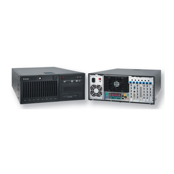
Page 14: Panels And Cabling
Panels and Cabling This section provides information on: Installation Overview • • Front Panel Features • Rear Panel Features Installation Overview Turn off and disconnect the VNM Recorder and all existing devices. Mount the recorder, if necessary, as described in the Mounting section on page 72. - Page 15 SCA / SATA drive panel — This panel houses the RAID5 hard drives. One hard drive is referred to as a hot spare drive, which is a drive that is inactive until an active drive fails. When an active drive fails, the hot spare drive rebuilds the data of the failed drive so that the system can recover.
-
Page 16: Rear Panel Features
USB (Universal Serial Bus) ports — Insert any compatible USB device into these ports. Use an external USB storage device with these ports to update the system. CD/DVD drive — Insert any compatible CD or DVD into this drive. This drive is used for system updates or software installation. - Page 17 Ethernet connector (eth0) — Connect a RJ-45 cable to this port. This port connects to a primary network and is the default network port that should be used to connect to a VN-Matrix network. Ethernet connector (eth1) — Connect a RJ-45 cable to this port. This port connects to a secondary network.
-
Page 18: Recorder Configuration And Hardware Setup
Connect a mouse, a keyboard, and a computer monitor (for configuration purposes) to the VNM Recorder (see Rear Panel Features on page 10). Use a network switch to connect a primary VN-Matrix network to the rear panel Ethernet connector ( ) of the VNM Recorder (see Rear Panel Features). -
Page 19: Vnm Recorder Power Up Procedure
VNM Recorder Power Up Procedure Use the following procedure to power up the VNM Recorder. NOTE: Before turning on the VNM Recorder, ensure that all necessary devices are powered on and connected properly. Press the power button on the front of the unit to initialize the bootup sequence. After bootup is complete, the following login screen appears if a local monitor is connected. -
Page 20: Login Information
Login Information NOTES: • A mouse, keyboard, and monitor must be connected to the VNM Recorder to log in to the unit itself. • Login information is case sensitive. • It is only necessary to log in to the VNM Recorder when it requires configuration. The VNM Recorder does not require login information for normal operation. -
Page 21: Vnm Recorder Power Down Procedure
VNM Recorder Power Down Procedure Use the following methods to safely power down the VNM Recorder. Using the Front Panel If the VNM Recorder is not logged into: Press and release the front panel power button. The recorder takes approximately 20 to 30 seconds to power-down. If the VNM Recorder is logged into: Press and hold the power button until the LED of the power button turns off. -
Page 22: Using The Keyboard And Mouse
Mouse and Keyboard Shut Down Confirmation Window Choosing the Controller Device In any VN-Matrix system, one device needs to be configured as a controller. The controller acts as a central point of reference for each device, manages all of the system communications to every matrix device present, and also serves the web-based control interface to the user. -
Page 23: Configuring The Vnm Recorder
255.255.255.0 Controller IP Address: 192.168.254.254 NOTE: Using these settings, the VN-Matrix encoder/decoder unit(s) must use IP addresses within the range 192.168.254.1 through 192.168.254.253 and use the same subnet mask. The default network settings can also be changed to match an existing network setup. - Page 24 Select the (upper Ethernet connector; primary network) device line to highlight it. If eth0 there is a network cable present and it is connected to a switch, the status should read Active. Click . The status of the device should now read Inactive. Deactivate eth0 Double-click on the...
- Page 25 If changes were made, a dialog box appears asking to confirm the changes. Click to confirm and save the changes (see figure 13). Figure 13. Confirm Settings Window The following dialog box appears (see figure 14). Click to continue. Figure 14. Settings Saved Window A loading dialog box appears and the necessary changes are made to the system.
- Page 26 Stage 2 — Setting the controller IP address If necessary, enter the administrator username and password at the login screen (see Login Information on page 14 for username and password information). From the desktop, double-click on Computer > Filesystem > home > matrix_rec (see figure 15, , and Double-click on the folder that contains the latest release of the recorder software...
- Page 27 Near the bottom of this file are two values named with st_controlIp st_localIp0 an IP address listed under each (see figure 16). Edit these values as follows. If the VNM Recorder is the controller device, edit both values to match the •...
-
Page 28: Configuring The Vn-Matrix Encoders And Decoders
15). Configuring the VN-Matrix Encoders and Decoders For the VNM Recorder to function properly, update each VN-Matrix device to point to the new IP address of the controller device. For information on how to configure the encoders and decoders, see the VN-Matrix 200 Series User Guide, VN-Matrix 225 Series User Guide, VN-Matrix 300 User Guide, and the VN-Matrix 325 User Guide. -
Page 29: About The Web-Based User Interface
The web-based user interface is an application that is used to configure the devices in a VN-Matrix network. It is accessed by using a web browser and entering in the IP address of the controller device. The user interface allows for system level configuration and can be used with any VN-Matrix device that is connected to the controller device. -
Page 30: Accessing The Web-Based User Interface
® ® any PC or laptop connected to the VN-Matrix network. With a web browser open, use the following steps to access the user interface. Type in the IP address of the controller device into the address bar of the web browser (for example, http://192.168.254.254). -
Page 31: Web-Based User Interface Control Options
Click or press <Enter> on the keyboard. The Device List page appears Log In (see figure 18). Figure 18. Device List Page For more information on how to control and navigate the user interface, see Web‑based User Interface Control Options below and Advanced Configuration on page 38. -
Page 32: Device List Page
Device List Page The Device List page lists all of the VN-Matrix devices detected on the network. This is also the first page that is seen after logging in (see figure 19). Figure 19. Device List Page NOTE: If devices are added after the page has been displayed, they may not automatically appear on this list. - Page 33 NOTE: To avoid compatibility issues, all devices must have the same version of firmware installed onto each device. Del — This column is used to remove devices from the VN-Matrix network. Clicking on the red icon brings up a confirmation dialog. Click to delete the selected device from the database.
-
Page 34: Recorder Device Page
Recorder Device Page Device List This page is accessed by selecting the VNM Recorder device on the (see page 26). Figure 20. Recorder Device Page The Recorder Device page shows the basic status for a VNM Recorder device. The device information is presented in four panels. NOTE: This guide references the Device page for the VNM Recorder only. - Page 35 — Using this mode on a source device stops streaming and disables • pass-through output. Using this mode on a display device disables all output. VN-Matrix 300 / 325 devices do not support standby mode. test — Using this mode on a device (source or display) shows a splash screen •...
-
Page 36: Recorder Page
Bandwidth statistics. For more information on monitoring bandwidth, see the VN-Matrix 200 Series User Guide, VN-Matrix 225 Series User Guide, VN-Matrix 300 User Guide, and the VN-Matrix 325 User Guide. VNM Recorder • About the Web-based User Interface... - Page 37 — This drop-down menu is used to select the RTP or TCP stream of each • available VN-Matrix stream. group — Checking this box allows channel recordings to be grouped together. • Grouped channels start, record, and stop together.
-
Page 38: Navigate Page
Navigate Page This page is accessed by selecting the VNM Recorder device on the Device List page (see page 26), clicking the icon located on the Configuration panel of the Recorder Recorder Device page (see page 28), and clicking on the tab. - Page 39 Group Recordings — A recording file is made up of a group of files sharing a common prefix all grouped together into a directory. When the box is checked, the content directory lists a logical • Group Recordings view of each type of stream that is present in the recording (this is the default setting).
- Page 40 Make Directory — Use this field to add a new directory. NOTE: It is recommended that a new directory is created for each recording so that they are easier to identify and retrieve for playback. Use the Content Directory to navigate to the appropriate location. Enter the name of the new directory into the field.
-
Page 41: Player Page
Player Page Device List This page is accessed by selecting the VNM Recorder device on the page (see page 26) and then selecting the icon located on the Configuration panel of the Player Recorder Device page (see page 28). Figure 23. Player Page The Player page is used to play back recorded media files that are stored on the VNM Recorder. - Page 42 Selecting a recording for replay The initial selection of a recorded stream is made by clicking on the appropriate filename shown in the Listing Directory (also known as the Content Directory; see figure 23 on the previous page and About the Content Directory on page 43).
- Page 43 channel — There are five channels that can be used for playback. Each playback channel contains the following parameters. prefix — Displays the name of the selected file. Only the first 11 characters of the • filename are displayed. sid — Displays the identification number of the filename. •...
-
Page 44: Advanced Configuration
Transport protocols must be kept consistent between the video and audio elements. The Config page modifies a single channel element of a VN-Matrix stream. This page is primarily used to monitor the current number of transport connections as well as to select... - Page 45 name — The channel name can be modified by editing this field and clicking Update This name is visible during source selection on a decoder (display) as well as during file selection on a recorder. The name should be comprised of letters, numbers and the underscore character.
- Page 46 • FEC is intended to be used for correcting network packet loss when using VN-Matrix 300 or 325 devices. This feature is currently not supported. Streams panel — This panel contains the following parameters. Multicast Enable — Checking this box allows the user to control whether a player •...
-
Page 47: Accounts Page
The Accounts page is primarily used to change the password that is used for logging into the designated controller device of the VN-Matrix system. This page is also used to manage the license that is assigned to the controller device and adjust the internal clock. -
Page 48: Vn-Matrix Encoder And Decoder Configuration
The user interface pages discussed in this guide are associated with the VNM Recorder. The VN-Matrix encoders and decoders may need to be configured using the other pages of the web-based user interface for the system to operate properly. For more information on how... -
Page 49: About The Content Directory
About the Content Directory This section discusses how to use the Content Directory for organizing and locating files. The following sections give an overview of how it is used and details some of the functionality of the Content Directory. This section provides information on: •... -
Page 50: Content Directory Basics
Figure 26. Navigate Page — Content Directory Figure 26 shows the Navigate page with a list of recorded files and contains the following settings: • check box is selected (by default). Group Recordings • The default storage path is initially set to . -
Page 51: Setting A Stream Storage Location
Switching between directories may take some time and the folder icon changes to a loading icon while waiting. After the directory has loaded, the field is updated with Update Path the current location. If the directory is not made available after ten seconds, an alert icon is displayed (see the icons below). -
Page 52: Understanding Saved Recordings With Multiple Elements
Understanding Saved Recordings With Multiple Elements Figure 27. Navigate Page — Multiple Element Recording When a recording contains multiple elements (such as video, audio, data, and whiteboard), the stream is saved as multiple directories containing multiple files. Figure 27 shows an example of a stream that has been saved using multi-channel recording, viewed on the Navigate page of the web-based user interface. -
Page 53: Renaming A Stream Or Directory
File Naming Table Channel Number Filename Section Description This is the text that was entered by CH1_M_UXGA_Audio_M the user in the filename column on Recorder page (see page 30). This is entered automatically by the VNM Recorder software. • 620032 = The serial number of the 620032.0.0_r0_s0 encoder unit •... -
Page 54: Recording And Playing Streams
25 while following the various procedures below. Initial Setup and Configuration This section talks about how to set up each VN-Matrix as a decoder or encoder. NOTE: All connections (streams) must be removed from the VN-Matrix system before a codec can be assigned as an encoder or a decoder. -
Page 55: Setting Up A Vn-Matrix Codec As An Encoder
The codec is now configured as a basic Save All decoder. For information on advanced decoder setup, see the VN-Matrix 200, 225, 300, or 325 user guides. Setting up a VN-Matrix Codec as an Encoder... -
Page 56: Switching A Codec Between Encoder And Decoder
Switching a Codec between Encoder and Decoder Device List From the page (see page 26), click on a VN-Matrix codec device. The Device page appears. Click (see figure 31, change device type NOTE: All connections (streams) must be removed from the codec before it can be assigned as an encoder or a decoder. -
Page 57: Initialize Recording
NOTE: Recording does not actually stop until is clicked. Update Creating Still Frames from a VN-Matrix Video Recording The gcode Frame Translator Utility allows existing VN-Matrix video recordings to be converted to a series of individual still frames (see gcode Frame Translator Utility Instructions on page 76). -
Page 58: Playing A Recorded Stream
Playback Preparation To prepare a stream for playback, follow the procedure below. Ensure that the VN-Matrix codec is configured as a decoder with a VNM Recorder channel set as the device (see Setting up a VN‑Matrix Codec as a Decoder Source on page 48). -
Page 59: Initialize Playback
Play Stop of the media stream. When playback is paused or stopped, the VN-Matrix decoder will behave as if the source data stream has stopped. If the feature is enabled on the decoder, the NoData Splash display will show the "No Source Datastream"... -
Page 60: Using Bookmarks
Using Bookmarks Bookmarks are used to set and quickly retrieve reference points within a stream. When a bookmark is created, it is stored in the Content Directory. Bookmarks are created by pressing the button while recording a stream using the Recorder page (see Bookmark... -
Page 61: About Alarms
Alarm Reference Tables Overview The VN-Matrix system is configured to generate alarms for error conditions. A list of these error conditions and their meanings are presented on the following pages. Alarms can be monitored using the web interface at the following locations. -
Page 62: Alarms Page
57). • Alarm Source — Select the device where the alarm is to change. Alarm filters may be set for either a single, specific unit or for all VN-Matrix 200, 225, 300, or 325 devices in the system. •... -
Page 63: Alarm Type
Applying Alarm Filter Settings Apply the alarm filter settings by clicking Apply Filter Change NOTE: Changes will be lost after the VN-Matrix system is powered down unless the tab is clicked to make changes permanent. Save All VNM Recorder • About Alarms... -
Page 64: Alarm List
Alarm List The alarm list provides information on all alarm events that are currently active. The alarm list is refreshed each time the tab is selected and is located at the bottom of the Alarms Alarms page. Alarm events that are listed may be sorted by Type (see figure 36, ), Raise Time ( and Severity ( ). -
Page 65: Alarm Logs Page
Alarm Logs Page This page is accessed by selecting the tab on the Device List page (see page 26) Alarms and then selecting the tab. Alarm Logs Figure 37. Alarm Logs Page The Alarm Logs page provides data on when an alarm condition was raised and cleared. The log holds a historical record of the last 200 alarm events. -
Page 66: Alarm Reference Tables
No SDI source Source is present, unable to lock. Critical, reporting lock Applicable to the VN-Matrix 300 / 325, ignore for VN-Matrix 200 / 225. Unsupported SDI Source is present, mode not Critical, reporting mode supported. Applicable to the VN-Matrix 300 / 325, ignore for VN-Matrix 200 / 225. -
Page 67: Alarm Type Description - Decoder
Alarm Type Description — Decoder Alarm Type Description Action Default Settings No decoder video Indicates that there is a valid Warning, reporting data connection, no video data present. Usually accompanied by "no source data stream" message in the web interface. No decoder mode No matching decoder mode for Warning, reporting... -
Page 68: Alarm Type Description - System Controller
Alarm Type Description — System Controller Alarm Type Description Action Default Settings Bad device The controller is unable to contact Check the device in question. Critical, reporting the specified device. The device is Is power applied? not available or has failed. Is the network cable or Note that this alarm is only network connection present? -
Page 69: Firmware Updates
Firmware Updates NOTE: The Update page on the web-based user interface is unable to update the firmware of the VNM Recorder directly. Use the procedure detailed in this section to update the firmware. This section provides information on: • Preparing the Firmware •... -
Page 70: Gathering Firmware Installation Information
From the matrix_rec window, right-click on the firmware package file and select the option. Extract Here NOTE: The firmware files are extracted to a subdirectory that is automatically named according to the package file, e.g. (where VNRecorder_verx.xx.x represents the version number). The directory path can be changed by renaming the folder after extraction has been completed (optional). -
Page 71: Installing The Firmware
Figure 38 shows example files. The text in bold and underlined config.xml admin.xml represents important information that will be needed during firmware installation. Figure 38. Config.xml and Admin.xml Text Files Installing the Firmware Use the following procedure to install the firmware onto the VNM Recorder. From the menu bar of the VNM Recorder desktop, select Applications >... - Page 72 Run the installation program by typing in the following command and pressing the <Enter> key. ./vnrecorder_install A series of prompts will start to request configuration information. Use the config.xml and the admin.xml files (see Gathering Firmware Installation Information on page 64) while using the Firmware Installation Table below to fill in the requested configuration information.
- Page 73 The firmware installation is complete when the command prompt is displayed in the terminal window. Manually close the terminal window. NOTE: The recording application is a service, which means that no application window will open after the installation has completed. To finalize the firmware installation, reboot the VNM Recorder by powering down and powering up the unit (see VNM Recorder Power Down Procedure...
-
Page 74: Browser Configuration
VN-Matrix systems operate correctly when using security that does not exceed the setting. Medium High NOTE: Setting the security slider to block all cookies prevents the VN-Matrix web interface from operating. VNM Recorder • Browser Configuration... - Page 75 TIP: If a high security level is required, click on the button and allow the Edit VN-Matrix web interface to use cookies (see figure 40). Figure 40. Per Site Internet Options To enable JavaScript, select the tab (see figure 41).
- Page 76 Scroll down to the Scripting setting and under Active scripting, select Enable (see figure 42). Figure 42. Custom Level Security Options Click on both dialogs to close and save the new settings. VNM Recorder • Browser Configuration...
-
Page 77: Mozilla Firefox (Version 1.3 Or Above)
Mozilla Firefox (version 1.3 or above) Open Mozilla Firefox and select . The Preferences window Edit > Preferences appears. To enable cookies, go to the category and choose Privacy & Security Cookies (see figure 43). Figure 43. Cookie Preferences Ensure that either the Enable all cookies Enable cookies for the option is selected. -
Page 78: Mounting
Mounting This section outlines the various mounting options available for the VNM Recorder. Tower Installation • • Rack Installation Tower Installation Attach the appropriate feet to the unit and place it in a well ventilated area. The tower can be placed on its side (horizontally) on a hard surface with the cover latch facing up or placed standing up (vertically) on a flat surface. -
Page 79: Rack Mounting
Rack Mounting The supplied rack mount kit includes two rack rail assemblies. Each of these assemblies consist of three sections: an inner fixed rail that secures to the recorder frame, an outer rack rail that secures directly to the rack itself, and two rail brackets that also attach to the rack (see figure 45). - Page 80 Top Cover Feet (4) Figure 46. Preparing to Install the Rails Attach the rack handles to the inner rails. Align each inner rail (with the rack handle attached) to the screw holes located on the left and right side of the recorder. Secure the rails to the sides of the recorder frame (see figure 47).
- Page 81 Secure the outer rails to the rail brackets. NOTE: The two outer rails are left and right specific. Line up the inner rails on the recorder with the outer rails on the rack. Gently slide the recorder into the outer rails of the rack (see figure 48).
-
Page 82: Gcode Frame Translator Utility Instructions
To create a media file from a VN-Matrix recording: Use VN-Matrix encoders and recorders to create a VN-Matrix recording. Create a directory on the VN-Matrix recorder, where the still frames and audio file will be Recording File Directory Nomenclature stored (see on page 80). -
Page 83: Preparation For Using The Gcode Frame Translator Utility
Preparation for Using the gcode Frame Translator Utility The gcode utility is run in a command window on the recorder where the required recording is stored. A command window may be opened from a remote Windows PC using WinSCP. Using WinSCP and PuTTY Open WinSCP and enter the IP address of the VN-Recorder. -
Page 84: Opening A Command Line Window
Opening a command line window Use PuTTY to open a command window session from WinSCP. From the Commands menu, select (see figure 51, Open in PuTTY Figure 51. Open a Command Window Session A command line window opens with a password prompt: Using username "matrix_rec". -
Page 85: Description Of The Frame Translator Utility
Description of the Frame Translator Utility The Frame Translator utility is a command line utility that is run from a terminal window on the VN-Matrix Recorder. The command line follows this structure: ./gcode command flags The available command flags are:... -
Page 86: Recording File Directory Nomenclature
Naming element Explanation Refers to the name assigned to the VN-Matrix encoder at the time of the recording. Refers to the serial number of the VN-Matrix encoder. _5400036 This digit refers to the type of recorded content. The options are: •... -
Page 87: Frame Translation Procedure
Enter the name of the folder and click in the dialog box. Navigate to the directory holding the Frame Translator utility. The gcode frame translator utility may be found in the same directory as the VN-Matrix recorder application at the following location: /home/matrix_rec/VNRecorder_verx.y.z where denotes the version number of the VN-Matrix application files. -
Page 88: Example Strings
Press <Enter> to run the command. If an error is detected in the command line, an indicator message appears in the terminal window. If the command line is valid, the utility exports one image file per video frame to the designated output directory. -
Page 89: Example 2 - Decoding A File To Targa Files And Placing Them In A Specified Output Directory
Example 2 — decoding a file to Targa files and placing them in a specified output directory The command is: ./gcode ‑t ‑o /home/matrix_rec/Targa ‑i /home/matrix_rec/Storage/SAC_ Test/ Dave_Gilmour_Dimming_of_the_Day_620027.0.0_r0_s0.rec • Since there is no flag, the frames are not displayed as they are generated. ‑g •... -
Page 90: Example 3 - Start Decoding A File At A Time Other Than The Beginning Of The Recording
Example 3 — start decoding a file at a time other than the beginning of the recording The command is: ./gcode ‑g ‑s 17:45:37.53 ‑i /home/matrix_rec/Storage/SAC_Test/ Dave_Gilmour_Dimming_of_the_Day_620027.0.0_r0_s0.rec • The file conversion starts ten seconds into the recording at 17:45:37.53 Example 4 — finish decoding a file at a time other than the end of the recording The command is: ./gcode ‑g ‑f 17:46:27.53 ‑i /home/matrix_rec/Storage/SAC_Test/... -
Page 91: Example 1
Example 1: VideoStartTime=17:43:13.84 Video Finish Time = 17:49:11.36 Video file Audio Start Time = 17:45:35.41 Audio Finish Time = 17:49:11.20 Audio file In the above diagram, the start and end times of the video and audio files are different. NOTE: The difference in start time is exaggerated to illustrate this point. In practice, the difference will be much smaller. - Page 92 Extron Electronics makes no further warranties either expressed or implied with respect to the product and its quality, performance, merchantability, or fitness for any particular use. In no event will Extron Electronics be liable for direct, indirect, or consequential damages resulting from any defect in this product even if Extron Electronics has been advised of such damage.
Need help?
Do you have a question about the VN-Matrix and is the answer not in the manual?
Questions and answers