
Related Manuals for Extron electronics Universal Interfaces RGB 130xi


Summary of Contents for Extron electronics Universal Interfaces RGB 130xi
- Page 1 User’s Manual RGB 130 xi xi xi xi xi , 134 xi xi xi xi xi , 150 xi xi xi xi xi Universal Interfaces 68-410-02 Printed in the USA...
- Page 2 Precautions Safety Instructions • English This symbol is intended to alert the user of important operating and maintenance (servicing) instructions in the literature provided with the equipment. This symbol is intended to alert the user of the presence of uninsulated dangerous voltage within the product's enclosure that may present a risk of electric shock.
-
Page 3: Table Of Contents
Table of Contents Chapter 1 • Introduction About this Manual About the Interfaces Features ... 1-1 Chapter 2 • Controls and Installation Front and Rear Panels RGB 150xi front panel features ... 2-1 RGB 150xi rear panel features ... 2-2 RGB 130xi front panel features ... - Page 4 RGB 130xi xi xi xi xi , 134xi xi xi xi xi , 150xi xi xi xi xi Table of Contents...
-
Page 5: About The Interfaces
RGB 130 xi xi xi xi xi , 134 xi xi xi xi xi , 150 xi xi xi xi xi Chapter One Introduction About this Manual About the Interfaces Features RGB 130xi xi xi xi xi , 134xi xi xi xi xi , 150xi xi xi xi xi Table of Contents... -
Page 6: About This Manual
Introduction About this Manual This manual documents three universal interfaces: RGB 130xi, RGB 134xi, and RGB 150xi. Unless otherwise specified, any references to “the interface” shall refer to the features or operation of all three interfaces. About the Interfaces The RGB 130xi, 134xi, and 150xi are universal interfaces with a video bandwidth of 300 MHz and a horizontal frequency range of 15-150 kHz. -
Page 7: Chapter 2 • Controls And Installation
RGB 130 xi xi xi xi xi , 134 xi xi xi xi xi , 150 xi xi xi xi xi Chapter Two Controls and Installation Front and Rear Panels Installation RGB 130xi xi xi xi xi , 134xi xi xi xi xi , 150xi xi xi xi xi Introduction... -
Page 8: Front And Rear Panels
Controls and Installation Front and Rear Panels RGB 150xi xi xi xi xi front panel features AUDIO Figure 2-1 — RGB 150 xi xi xi xi xi front panel RGB 130xi xi xi xi xi , 134xi xi xi xi xi , 150xi xi xi xi xi Controls and Installation INPUTS BUFFERED LOCAL MONITOR OUTPUT... - Page 9 RGB 150xi xi xi xi xi rear panel features 100-240 0.5A MAX. GAIN/ PEAK 100% UNITY 50/60 Hz Figure 2-2 — RGB 150 xi xi xi xi xi rear panel AC power input — standard IEC AC power connector (100 - 240VAC 50/60 Hz) 3-position gain/peak switch —...
-
Page 10: Rgb 130Xi Front Panel Features
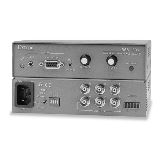
Controls and Installation, cont’d RGB 130xi xi xi xi xi front panel features AUDIO Figure 2-3 — RGB 130 xi xi xi xi xi front panel RGB 130xi xi xi xi xi , 134xi xi xi xi xi , 150xi xi xi xi xi Controls and Installation INPUTS ANALOG/ECL H. -
Page 11: Rgb 130Xi Rear Panel Features
RGB 130xi xi xi xi xi rear panel features 100-240 0.5A MAX. GAIN/ PEAK 100% UNITY 50/60 Hz Figure 2-4 — RGB 130 xi xi xi xi xi rear panel * Unity sets the output level equivalent to the input, with no added peaking. -
Page 12: Rgb 134Xi Front Panel Features
Controls and Installation, cont’d RGB 134xi xi xi xi xi front panel features Figure 2-5 — RGB 134 xi xi xi xi xi front panel RGB 130xi xi xi xi xi , 134xi xi xi xi xi , 150xi xi xi xi xi Controls and Installation INPUTS AUDIO ANALOG/ECL... -
Page 13: Rgb 134Xi Rear Panel Features
RGB 134xi xi xi xi xi rear panel features 100-240 0.5A MAX. GAIN/ PEAK 100% UNITY 50/60 Hz Figure 2-6 — RGB 134 xi xi xi xi xi rear panel AC power input — standard IEC AC power connector (100 - 240VAC 50/60 Hz) 3-position gain/peak switch —... -
Page 14: Installation
Controls and Installation, cont’d Installation Easy setup procedure Except where noted, the installation procedures for the RGB 130xi, 134xi, and 150xi are the same. See “Cabling” in this chapter for more information. * RGB 150xi is analog only RGB 130xi xi xi xi xi , 134xi xi xi xi xi , 150xi xi xi xi xi Controls and Installation If desired, mount the interface to a desk or other suitable surface using Extron’s optional mounting kit. -
Page 15: Mounting The Interface
Mounting the interface To mount the interface under a desk or in a podium, do the following: Attach the mounting brackets to the interface using six machine screws supplied with the mounting kit (see figure 2-7). Figure 2-7 — Attaching the under desk brackets Using the to-scale template at the back of this manual to guide you, mark the four screw holes on the underside of the surface to which you are mounting... - Page 16 Controls and Installation, cont’d To mount the interface through a desk or table, do the following: Figure 2-9 — Attaching the through desk Figure 2-10 — Mounting the interface in a RGB 130xi xi xi xi xi , 134xi xi xi xi xi , 150xi xi xi xi xi Controls and Installation Attach the mounting brackets to the interface using four machine screws and washers (supplied with the mounting kit), as indicated in figure 2-9.
-
Page 17: Cabling
Cabling Each interface can connect to the computer or workstation’s local monitor and to a projector or other display device. The diagrams below show how to connect each of the interfaces. Connect the computer to the interface’s Analog/ECL connector. Front MBC Buffer MBC/LBC Cable... - Page 18 Controls and Installation, cont’d PC Computer Figure 2-13 — RGB 150xi xi xi xi xi installation RGsB RGBS RGBHV 2-11 RGB 130xi xi xi xi xi , 134xi xi xi xi xi , 150xi xi xi xi xi Controls and Installation Front IN P IV E...
-
Page 19: Connecting Audio Output
Connecting audio output Before connecting audio, determine whether your audio system is unbalanced or balanced. Then, follow the instructions below to connect unbalanced audio, or the instructions for “Balanced audio” to connect balanced audio. Unbalanced audio To attach the interface to an unbalanced audio system, do the following: Attach the audio cable to an unbalanced powered speaker input connector (tip and sleeve), as shown... - Page 20 Controls and Installation, cont’d Balanced audio To attach the interface to a balanced audio system, do the following: 2-13 RGB 130xi xi xi xi xi , 134xi xi xi xi xi , 150xi xi xi xi xi Controls and Installation Slide the audio cable connector into the audio output connector on the interface.
-
Page 21: Setting The Dip Switches
Setting the DIP switches DIP switches can be found on the front panel of the RGB 150xi and on the rear panels of the RGB 150xi, 130xi, and 134xi. The switches may be either the rocking type or the sliding type. The RGB 150xi has two pin termination DIP switches to provide proper ID bit termination for a laptop computer that is not attached to a local... - Page 22 Controls and Installation, cont’d 2-15 RGB 130xi xi xi xi xi , 134xi xi xi xi xi , 150xi xi xi xi xi Controls and Installation devices, such as LCD (liquid crystal display), DLP (digital lamp processing) and plasma displays. OFF —...
-
Page 23: Setting Internal Jumpers
Setting internal jumpers The jumpers inside the interface(s) are set at the factory for optimal use by most systems. However, you can change a jumper setting to meet the needs of a particular system. The user-configurable, internal jumpers control the following functions: •... - Page 24 Controls and Installation, cont’d Figure 2-16 — Circuit board jumper locations Figure 2-17 — Changing jumper settings 2-17 RGB 130xi xi xi xi xi , 134xi xi xi xi xi , 150xi xi xi xi xi Controls and Installation pins 1 and 2 connected: pins 2 and 3 connected: Rear J20: Sync polarity...
- Page 25 The jumpers perform the following functions: J20: Sync polarity jumper — This jumper adjusts the output sync polarity. Horizontal (H) and vertical Negative Follow (V) sync output can either follow input sync polarity, or be forced to negative. • If the jumper is placed on pins 1 and 2, output H and V sync polarities will be forced to negative.
- Page 26 2-19 RGB 130xi xi xi xi xi , 134xi xi xi xi xi , 150xi xi xi xi xi Controls and Installation...
-
Page 27: Appendix
RGB 130 xi xi xi xi xi , 134 xi xi xi xi xi , 150 xi xi xi xi xi Appendix Specifications Accessories and Part Numbers Mounting Templates RGB 130xi xi xi xi xi , 134xi xi xi xi xi , 150xi xi xi xi xi Operation... -
Page 28: Video Output
Appendix Specifications — RGB 130xi, 134xi, 150xi Video input Number/type ... 1 analog RGBHV, RGBS, RGsB, Connectors ... 1 15-pin HD male (150xi) Nominal level(s) ... Analog — 0.3V to 1.5V p-p Maximum level(s) ... Analog — 1.5V p-p Impedance ... 75 ohms or (for 130xi and 134xi) HI Horizontal frequency ... -
Page 29: Audio Input
Max. rise/fall time ... 3.5 nS Polarity ... RGBHV: when RGBHV is input,polarity Audio input Number/type ... 1 PC level stereo, unbalanced Connectors ... 1 3.5 mm stereo jack, 2 channel; tip (L), Impedance ... 10 kohms, DC coupled Minimum level ... 100mV Maximum level ... - Page 30 Appendix, cont’d Enclosure type ... Metal Enclosure dimensions of 130xi and 150xi ... 1.70" H x 6.35" W x 6.00" D Enclosure dimensions of 134xi ... 1.68" H x 8.70" W x 6.00" D Shipping weight ... 6 lbs (2.7 kg) Vibration ...
-
Page 31: Accessories And Part Numbers
Accessories and Part Numbers Thunder™ Mounting Kits Under desk mounting kit ... Through desk mounting kit ... Monitor breakout cables: RGB 130xi xi xi xi xi and RGB 134xi xi xi xi xi MBC VGA/XGA HR ... MBC Mac/Quadra ... MBC SUN Sparc HR ... - Page 32 Appendix, cont’d BNC cables BNC-5 3’ HR ... BNC-5 6’ HR ... BNC-5 12’ HR ... BNC-5 25’ HR ... BNC-5 50’ HR ... BNC-5 75’ HR ... BNC-5 100’ HR ... BNC-5 3’ HRP ... BNC-5 6’ HRP ... BNC-5 12’...
- Page 33 RGB 130xi xi xi xi xi , 134xi xi xi xi xi , 150xi xi xi xi xi Appendix...
- Page 34 RGB 130xi xi xi xi xi , 134xi xi xi xi xi , 150xi xi xi xi xi Appendix...
- Page 35 RGB 130xi xi xi xi xi , 134xi xi xi xi xi , 150xi xi xi xi xi Appendix...
- Page 36 RGB 130xi xi xi xi xi , 134xi xi xi xi xi , 150xi xi xi xi xi Appendix...
-
Page 37: Fcc Class A Notice
FCC Class A Notice Note: This equipment has been tested and found to comply with the limits for a Class A digital device, pursuant to part 15 of the FCC Rules. These limits are designed to provide reasonable protection against harmful interference when the equipment is operated in a commercial environment. - Page 38 Beeldschermweg 6C, 3821 AH Amersfoort 1230 South Lewis Street, Anaheim, CA 92805 800.633.9876 714.491.1500 F AX 714.491.1517 +31.33.453.4040 FAX +31.33.453.4050 The Netherlands EXTRON ELECTRONICS, ASIA EXTRON ELECTRONIC INFORMATION 41B Kreta Ayer Road, Singapore 089003 WEB™: www.extron.com XTRON +65.226.0015 FAX +65.226.0019 FAX™: 714.491.0192...
Need help?
Do you have a question about the Universal Interfaces RGB 130xi and is the answer not in the manual?
Questions and answers