Extron electronics Extron IPL T S4 Setup Manual
Extron electronics interfaces setup guide
Hide thumbs
Also See for Extron IPL T S4:
- User manual (79 pages) ,
- Setup manual (29 pages) ,
- User manual (79 pages)
Table of Contents
Advertisement
Quick Links
Download this manual
See also:
User Manual
Advertisement
Table of Contents

Related Manuals for Extron electronics Extron IPL T S4


Summary of Contents for Extron electronics Extron IPL T S4
-
Page 1: Setup Guide
Setup Guide IPL T S Series Interfaces 68-1377-01 Rev. C 11 08... - Page 2 Safety Instructions • English This symbol is intended to alert the user of important operating and maintenance (servicing) instructions in the literature provided with the equipment. This symbol is intended to alert the user of the presence of uninsulated dangerous voltage within the product’s enclosure that may present a risk of electric shock.
-
Page 3: Fcc Class A Notice
安全须知 • 中文 这个符号提示用户该设备用户手册中 有重要的操作和维护说明。 这个符号警告用户该设备机壳内有暴 露的危险电压,有触电危险。 注意 阅读说明书 • 用 户 使 用 该 设 备 前 必 须 阅 读 并 理 解 所 有 安 全 和 使 用 说 明 。 保存说明书 • 用户应保存安全说明书以备将来使 用。 遵守警告 • 用户应遵守产品和用户指南上的所有安 全和操作说明。... -
Page 5: Table Of Contents
Chapter One • Introduction About this Manual IPL T S Series Products IPL T S1 ... 1-3 IPL T S2 ... 1-3 IPL T S4 ... 1-3 IPL T S6 ... 1-3 Global Configurator System requirements ... 1-5 Installing Global Configurator ... 1-5 Chapter Two •... - Page 6 Table of Contents, cont’d Launching the GlobalViewer Interface Step fourteen: launch GlobalViewer ... 3-22 All trademarks mentioned in this manual are the properties of their respective owners. IPL T S Series Interfaces • Table of Contents ... 3-22 68-1377-01 Rev. C 11 08...
-
Page 7: Chapter One • Introduction
IPL T S Series Interfaces Chapter One Introduction About this Manual IPL T S Series Products Global Configurator... -
Page 8: About This Manual
About this Manual This setup guide describes the: • IPL T S Series products • Global Configurator application • IPL T S Series hardware installation • IPL T S Series software configuration IPL T S Series Products The Extron IPL T S Series interface boxes can be installed as nodes on an Ethernet-based audio/video (A/V) network. -
Page 9: Ipl T S1
The IPL T Series products include: IPL T S1 • 12 VDC power supply • RJ-45 Ethernet receptacle • 9-pin D RS-232 serial port IPL T S2 • 12 VDC power supply • RJ-45 Ethernet receptacle • Two 9-pin D RS-232, RS-422, or RS-485 serial ports - or - •... -
Page 10: Global Configurator
Introduction, cont’d Global Configurator Global Configurator (GC) is a software application that gives users the ability to create a single configuration file of all the controlled devices on their audio/video (A/V) network. There are two types of devices in an A/V system: •... -
Page 11: System Requirements
Using GC you can configure a single room controller, or create a web-based remote monitoring system for hundreds of A/V devices in multiple locations. You may configure an IPL T S Series interface using GC without having the device physically connected to the A/V network. System requirements The minimum system requirements for the PC on which you install Global Configurator include:... - Page 12 Introduction, cont’d Insert the Extron Software Products CD into your drive. Wait for the Extron Software Products page to load. Click on the Software icon. Scroll down to the Global Configurator description and click the Install link in the far right column. Follow the remaining system prompts.
-
Page 13: Chapter Two • Hardware Setup
IPL T S Series Interfaces Chapter Two Hardware Setup Front Panel Rear Panel Power Connection Local Area Network (LAN) Connection Serial Device Connection... -
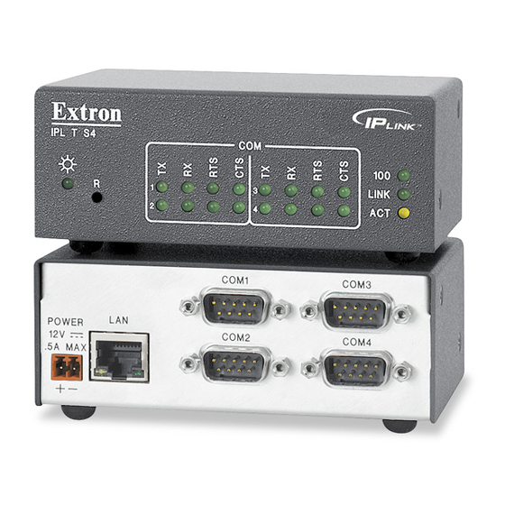
Page 14: Front Panel
Front Panel The front panel has a recessed Reset button and the LED indicators described below: Power LED — green when power is on Reset button — recessed multiple function reset button TX LED — green when data is being transmitted RX LED —... -
Page 15: Rear Panel
Rear Panel The rear panel has connectors for power, control, signal input, and signal output, and indicators as described below. Power receptacle — connects the supplied 12 VDC power supply LAN Activity LED — yellow LED blinks when sending and receiving data LAN receptacle —... -
Page 16: Power Connection
Hardware Setup, cont’d Power Connection To connect the power supply: Insert the 2-pole captive screw connector into the power supply receptacle on the rear panel of the interface. Connect the female end of the power supply AC cord into the power supply and connect the male plug end into a 110 VAC receptacle. -
Page 17: Serial Device Connection
Pinouts for the two types of Ethernet cables are shown below: Pins: 1 2 3 4 5 6 7 8 Side View Insert Twisted Pair Wires RJ-45 Connector Serial Device Connection There are two types of serial connections: • 9-pin D connectors •... -
Page 18: 9-Pin D Connector
Hardware Setup, cont’d 9-pin D connector Connect any audio/video device using a serial cable with a 9-pin D connector to any one of the COM ports on the rear panel of an IPL T S Series interface. 00-05-A6-00-00-02 POWER .5A MAX COM Ports with 9-pin D Connectors Pinouts for the 9-pin D connector are shown in the illustration and table below. - Page 19 00-05-A6-00-00-02 POWER COM1 .5A MAX TX RX COM Ports with Captive Screw Connectors The IPL T S6 has four COM ports (3 thru 6) with captive screw connectors that are independent of COM ports 1 and 2, which have 9-pin D connectors. 00-05-A6-00-00-06 POWER COM3...
- Page 20 Hardware Setup, cont’d IPL T S Series Interfaces • Hardware Setup...
-
Page 21: Chapter Three • Software Setup
IPL T S Series Interfaces Chapter Three Software Setup Creating a Global Configurator Project File Configuring a New Device Building and Uploading a GC File Launching the GlobalViewer Interface ®... -
Page 22: Creating A Global Configurator Project File
Creating a Global Configurator Project File After you have installed the Global Configurator (GC) application on your PC, follow the steps in this chapter to download device drivers, create a GC project file, configure your IPL T S Series devices, and launch the GlobalViewer Step one: download device drivers Software drivers for your audio/video devices are available free from the Extron web site at www.extron.com. - Page 23 Click the right arrow (Subscribe) button. Repeat steps 3 through 5 for each type of device you plan to add to your audio/video network. Click the Download button. The Download Complete dialog box opens. Click the Close button. Click OK. IPL T S Series Interfaces •...
-
Page 24: Step Two: Create A New Project
Software Setup, cont’d Step two: create a new project To create a new Global Configurator project file: Click File > New. The Start Options dialog box opens. Select Create a New Project. Click OK. The Project Settings dialog box opens (see next page). IPL T S Series Interfaces •... - Page 25 Enter the IP address of the first device you will add to your GC project file in the Next Assigned IP Address field. Make the desired date/time selections. Click OK. The Add Device dialog box opens. IPL T S Series Interfaces • Software Setup...
-
Page 26: Step Three: Add A Device
Software Setup, cont’d Step three: add a device There are four ways to launch the Add Device dialog box: • Press Ctrl+A on the keyboard • Click Edit > Add Device... • Click the Add Device icon • When you select Create a Project in the Start Options dialog box, and follow the prompts, the Add Device dialog is the second dialog box to open. - Page 27 If the device you are adding is password protected, enter the appropriate admin and user passwords. (The default condition is no admin or user password.) Click Auto Configure IP Address. Enter the device’s MAC address (found on a label on the rear of the device).
-
Page 28: Step Four: Define The Location Of The New Device
Software Setup, cont’d Step four: define the location of the new device Global Configurator allows you to keep track of the devices on your audio/video network by creating a custom tree of folders in which you can place and organize your audio/video devices. This GlobalViewer Tree can be up to eight levels deep and have multiple folders in each level. -
Page 29: Step Five: Save The New Global Configurator File
Step five: save the new Global Configurator file To save the new GC project file: Click File > Save - or - click the Save icon. If the file has not previously been saved, the Save As dialog box opens. Enter a unique name in the Project Name field. -
Page 30: Configuring A New Device
Software Setup, cont’d Configuring a New Device Step six: configure contacts The Contact Manager dialog box is used to enter the name, e-mail address, and company name of the network’s contacts. To configure contacts: Click Edit > Contact Manager... Complete the Name, Email, and Company fields. Click Add. -
Page 31: Step Seven: Configure E-Mail
Step seven: configure e-mail The Email Manager dialog box is used to create custom e-mails that are delivered as directed by the settings in the GC Schedule and Monitor dialog boxes. To create custom e-mails: Click Edit > Email Manager... Complete the Name, Subject, and Body fields. -
Page 32: Step Eight: Assign Device Drivers
Software Setup, cont’d Step eight: assign device drivers The Driver Configuration tab of Global Configurator allows you to assign a device driver to each serial port of the device. To assign a device driver: Select a serial port in the IP Link Tree window. The Driver Configuration tab opens. -
Page 33: Step Nine: Set Scheduled Actions And E-Mail Deliveries
Step nine: set scheduled actions and e-mail deliveries The Schedule tab is used to set scheduled actions and e-mail deliveries. A single schedule can include both actions and e-mail assignments. To schedule an action: Click the Schedule tab. Click the Add Schedule button. The Scheduled Actions Wizard dialog box opens. - Page 34 Software Setup, cont’d Enter a unique schedule name. Select the schedule times. Click Next. Click Actions. Select a subject port (device). Select an available option (action). Click Apply Action. IPL T S Series Interfaces • Software Setup 3-14...
- Page 35 To schedule an e-mail delivery: Click the Schedule tab. Click the Add Schedule button. The Scheduled Actions Wizard dialog box opens. Enter a unique scheduled action name. Select the schedule times. Click Emails. IPL T S Series Interfaces • Software Setup 3-15...
- Page 36 Software Setup, cont’d The Add an Email window opens in the right pane. Select an e-mail message. Select a recipient (Contact). Click Apply Email/Contacts. The new e-mail and recipient is now displayed in the left pane. Click the Contact Manager button to create new contacts (if desired).
-
Page 37: Step Ten: Set Monitored Conditions
Step ten: set monitored conditions The Monitor tab is used to respond with an action or e-mail to a specified condition or event. Actions vary by selected device, and include options such as Enable/Disable PINs, Lockout Front Panel, Time Delay, etc. Custom e-mails can be created and sent to specified e-mail addresses following specified conditions or events. - Page 38 Software Setup, cont’d Enter a unique monitored condition name. Click Next. Click Conditions. Select a subject port (device). Select an available option. Edit the Name field (if desired). Set the desired condition test parameters (if available). Click Apply Condition. Click Next. IPL T S Series Interfaces •...
-
Page 39: Building And Uploading A Gc File
Click Next again to add an e-mail notification. Select an e-mail message and contacts, and click Apply Email/Contacts. Click Done. The dialog box closes. Building and Uploading a GC File Before a Global Configuration (GC) file is active in the GlobalViewer interface, the GC file must be “built”... -
Page 40: Step Twelve: Upload The Global Configurator File
Software Setup, cont’d Step twelve: upload the Global Configurator file When the build process completes, the Upload dialog box opens. Click the Begin button. When the upload process completes, the Progress and Status fields are updated to indicate completion. Click the Test GV System button to view the GlobalViewer Host interface. -
Page 41: Step Thirteen: Change Device Settings (If Desired)
Step thirteen: change device settings (if desired) If for any reason you need to change any of the previously configured settings: Click Tools > Change Device Settings. Select a device. Click Settings to open the Settings drop-down listing. Select and change the desired setting(s), for example: Set Mail Server..., Set Gateway..., Set Subnet Mask..., etc. -
Page 42: Step Fourteen: Launch Globalviewer
Software Setup, cont’d Launching the GlobalViewer Interface GlobalViewer is a graphical user interface that is generated by Global Configurator (GC). When a GC file is built and uploaded to a GlobalViewer host device, you can launch the GlobalViewer interface by opening an Internet browser and entering the host device’s IP address in the browser address field. - Page 43 IPL T S Series Interfaces • Software Setup 3-23...
- Page 44 Extron Electronics warrants this product against defects in materials and workmanship for a period of three years from the date of purchase. In the event of malfunction during the warranty period attributable directly to faulty workmanship and/or materials, Extron Electronics will, at its option, repair or replace said products or components, to whatever extent it shall deem necessary to restore said product to proper operating condition, provided that it is returned within the warranty period, with proof of purchase and description of malfunction to:...
-
Page 45: Add A Device
Setup Guide Checklist Chapter 1: Download and install Global Configurator. Chapter 2: Make the IPL T S cable connections. Chapter 3: Create a Global Configurator project file. Add and configure a device. Build and upload the GC project file. Launch the GlobalViewer Extron USA - West Extron USA - East Headquarters...
Need help?
Do you have a question about the Extron IPL T S4 and is the answer not in the manual?
Questions and answers