
Subscribe to Our Youtube Channel
Related Manuals for Orban OPTIMOD 6300


Summary of Contents for Orban OPTIMOD 6300
- Page 1 Operating Manual OPTIMOD 6300 Digital Multipurpose Audio Processor Version 2.3 Software...
- Page 2 European Parliament, this product must not be discarded into the municipal waste stream in any of the Member States. This product may be sent back to your Orban dealer at end of life where it will be reused or recycled at no cost to you.
-
Page 3: Important Safety Instructions
IMPORTANT SAFETY INSTRUCTIONS All the safety and operating instructions should be read before the appliance is operated. Retain Instructions: The safety and operation instructions should be retained for future reference. Heed Warnings: All warnings on the appliance and in the operating instructions should be adhered to. Follow Instructions: All operation and user instructions should be followed. - Page 4 Safety Instructions (German) Gerät nur an der am Leistungsschild vermerkten Spannung und Stromart betreiben. Sicherungen nur durch solche, gleicher Stromstärke und gleichen Abschaltverhaltens ersetzen. Sicherungen nie überbrücken. Jedwede Beschädigung des Netzkabels vermeiden. Netzkabel nicht knicken oder quetschen. Beim Abziehen des Netzkabels den Stecker und nicht das Kabel enfassen.
- Page 5 (2) Check the other sections of the Manual (consult the Table of Contents and Index) to see if there might be some sug- gestions regarding your problem. (3) After reading the section on Factory Assistance, you may call Orban Customer Service for advice during normal Cali- fornia business hours. The number is (1) 510 / 351-3500.
- Page 6 20,000 volts. This is the spark or shock you may have felt when touching a doorknob or some other conductive surface. A much smaller static discharge is likely to destroy one or more of the CMOS semiconductors employed in OPTIMOD 6300. Static damage will not be covered under warranty.
- Page 7 Operating Manual OPTIMOD 6300 Digital Multipurpose Audio Processor Version 2.3 Software...
-
Page 8: Table Of Contents
OPTIMOD 6300 ..................1-11 OCATION OF At the transmitter is best ....................1-11 Where access to the transmitter is not possible ............1-12 OPTIMOD 6300 at the transmitter: gain control before the STL ......... 1-12 OPTIMOD 6300 ..........1-13 SING AS A... - Page 9 ............1-26 ONITORING ON OUDSPEAKERS AND EADPHONES ..............1-27 TREAMING AND ETCASTING PPLICATIONS Using OPTIMOD 6300 in Streaming Applications ............1-27 Loudness.......................... 1-27 Choosing your Encoder ....................1-27 EAS T ........................1-28 PC C ................1-29 ONTROL AND ECURITY ASSCODE ...................1-29 ARRANTY EEDBACK User Feedback......................1-29 LIMITED WARRANTY .....................1-29...
- Page 10 Distortion in Processing ....................3-4 Loudness and Distortion ....................3-5 Processing for Low Bit Rate Codecs................. 3-5 Speech/Music Detector..................... 3-6 Optimod 6300 in Radio-Oriented Applications: From Bach to Rock ....3-6 Sound-for-Picture Applications: Controlling Dynamic Range ......3-7 6300’ ..............3-8 BOUT THE...
- Page 11 : ..................3-69 UTOMATION To group multiple 6300s: ..................3-69 Navigation Using the Keyboard ................3-69 To Quit the Program....................3-70 About Aliases created by Optimod 6300 PC Remote Software ......3-70 Multiple Installations of Optimod 6300 PC Remote ...........3-70 6300 ............3-72 SING THE RODUCTION AND...
- Page 12 Discussion and Conclusions.................... 3-88 Section Maintenance ............................4-1 ....................4-1 OUTINE AINTENANCE ...............4-2 UBASSEMBLY EMOVAL AND EPLACEMENT ..................4-6 IELD UDIT OF ERFORMANCE Table 4-1: Typical Power Supply Voltages and AC Ripple ..........4-8 Section Troubleshooting ............................5-1 ................5-1 ROBLEMS AND OTENTIAL OLUTIONS RFI, Hum, Clicks, or Buzzes....................5-1 Poor Peak Modulation Control..................
- Page 13 IC O ..................5-14 ROUBLESHOOTING PAMPS .......................5-14 ECHNICAL UPPORT ......................5-14 ACTORY ERVICE ....................5-15 HIPPING NSTRUCTIONS Section Technical Data ............................6-1 ........................6-1 PECIFICATIONS Performance......................6-1 Installation .......................6-2 ......................6-5 IRCUIT ESCRIPTION Overview ........................6-5 Control Circuits ......................6-5 User Control Interface and LCD Display Circuits ...........6-6 Input Circuits......................6-8 Output Circuits......................6-9 DSP Circuit......................6-10 Power Supply ......................6-11...
-
Page 14: Index
Function Description Drawing Page DSP Chips; Local regulators. Contains: L and R Analog Inputs Schematic 1 of 9 6-31 L and R Analog Outputs Schematic 2 of 9 6-32 Digital Input and Sync Input Schematic 3 of 9 6-33 Digital Outputs Schematic 4 of 9 6-34 DSP Extended Serial Audio Inter-... - Page 15 analog output bit depth of internal processing 6- · 1 block diagram 6- · 43 circuit description 6- · 9 analog output 2- · 6 breakpoint 3- · 54 analog television Brilliance control 3- · 38 processing for 2- · 25, 28 BS.1770 analog TV LF accuracy ·...
- Page 16 MAX LPF 2- · 13, 20 cleaning front panel 4- · 1 soft buttons 3- · 1 clipper SYNC DELAY 2- · 19 control list 3- · 46 corrosion 4- · 1 clipper, bass 3- · 10 coupling controls 3- · 60 clipping 3- ·...
- Page 17 distortion Final Limit control 3- · 47 Firewall 2- · 54, 65 excessive 5- · 5 testing 4- · 9 Firmware troubleshooting 5- · 2 updating 8500 2- · 86 vs. loudness 3- · 5 five-band dither 2- · 27, 31, 34 attack time controls 3- ·...
- Page 18 Hard Clip Shape 3- · 47 J.17 headphones and 6300 digital I/O 1- · 10 deemphasis applied to digital audio input 6- low-delay monitoring 2- · 14, 24, 27 · 3 headphones 1- · 26 defined 1- · 10 headroom preemphasis applied to digital audio output in codecs 1- ·...
- Page 19 XE "presets:AGC 3-" XE "presets:protection AGC 3- · 44 Max Delta GR 3-" using 6300 as 3- · 23 look-ahead limiter 3- · 10 AGC 3- · 44 look-ahead limiting 3- · 4 MB Limit Drive control lossy data reduction etting 3- ·...
- Page 20 2- · 41 NEXT button 3- · 1 recovering from lost 2- · 44 NICAM 1- · 16 noise Orban installer program 2- · 53 PC board locator diagram 6- · 23 specification 6- · 1 PC control troubleshooting 5- · 2 null modem cable security 1- ·...
- Page 21 TV 5B Drama 3- · 33 video oriented 3- · 7 processing structures TV 5B Drama Coupled 3- · 33 TV 5B GEN PUR W/NR 3- · 32 two-band 3- · 32 TV 5B Gen Purp –LC 3- · 33 Proof of Performance 1- ·...
- Page 22 obtaining 6- · 14 specifications 6- · 1 spectral truncation safety limiter overshoot caused by 1- · 16 BS.1770 1- · 23 speech/music detector 3- · 6 BS.1770 3- · 13 Sports format 3- · 30 sample rate station ID at digital output 6- ·...
- Page 23 archiving 3- · 20 test tone creating 3- · 9, 15, 18, 19 frequencies 2- · 26 user presets 1- · 8 Threshold Bass Delta 3- · 45 Master Delta 3- · 45 Multiband Compression 3- · 58 time VPN, setting up 2- · 54, 65 daylight saving 2- ·...
-
Page 25: Section 1 Introduction
OPTIMOD 6300 DIGITAL INTRODUCTION Section 1 Introduction Crucial Information for Video Applications— Please Read! To make automatic loudness control as straightforward and dependable as possible, the 6300 operates somewhat differently from other Optimods. Dialnorm: The 6300 works very easily with Dolby Digital® transmission systems if you do one crucial thing: You must tell the 6300 what value of Dolby Digital Dialnorm metadata you are transmitting to your audience. - Page 26 INTRODUCTION ORBAN MODEL 6300 value of D that the Dolby Digital encoder is transmitting to your IALNORM audience. Setting Output Loudness: To set the 6300’s output loudness, adjust its value or adjust the MB L IALNORM IMITER RIVE control in the active Processing Preset.
-
Page 27: Using This Manual
Adobe Acrobat Reader’s text search function. The OPTIMOD 6300 Digital Audio Processor Orban’s all-digital Optimod 6300 Audio Processor can help you achieve the highest possible quality digital audio broadcast, digital television, and netcast audio process- ing. -
Page 28: User-Friendly Interface
The rest of Chapter 1 explains how OPTIMOD 6300 fits into the DAB and DTV broad- cast plants and how to use it for netcasting. Chapter 2 explains how to install it. -
Page 29: Flexible Configuration
OPTIMOD 6300’s outputs can be independently configured to emit the output of the AGC or the output of the multiband compressor/limiter, all configurable to use or bypass look-ahead limiting. So a 6300 can be configured to drive an... -
Page 30: Adaptability Through Multiple Audio Processing Structures
INTRODUCTION ORBAN MODEL 6300 OPTIMOD 6300 controls the audio bandwidth as necessary to accommodate the transmitted sample frequency. OPTIMOD 6300’s high frequency bandwidth can be switched instantly (typically in 1 kHz increments) between 10 kHz and 20 kHz. 20 kHz is used for highest-quality systems. 15 kHz meets the requirements of any system that uses 32 kHz sample frequency, while 10 kHz is appropriate for 24 kHz sample frequency. -
Page 31: Controllable
INTRODUCTION A special 2-band preset creates a no-compromise “Protect” function that is func- tionally similar to the “Protect” structures in earlier Orban digital processors. The 5-band and the 2-band structures can be switched via a mute-free crossfade. The 6300 includes third-generation CBS Loudness Controllers™ for DTV appli- cations. -
Page 32: Presets In Optimod 6300
(by connecting a Windows® computer to the 6300’s serial port through the sup- plied null modem cable). Presets in OPTIMOD 6300 There are two distinct kinds of presets in OPTIMOD 6300: factory presets and user presets. Factory Presets The Factory Presets are our “factory recommended settings” for various program formats or types. -
Page 33: Input/Output Configuration
Digital AES3 left/right inputs and dual outputs. Analog left/right inputs and outputs. OPTIMOD 6300 can be operated in either stereo or dual-mono mode. In dual-mono mode, processing parameters that determine the “sound” of the processor are the same on both channels. -
Page 34: Analog Left/Right Input/Output
You select whether OPTIMOD 6300 uses the digital or analog input either locally or by remote interface. If OPTIMOD 6300 is set to accept a digital input and the feed fails, OPTIMOD 6300 will automatically switch back to the analog input. -
Page 35: Computer Interface
6300 is to be used as a studio AGC. At the transmitter is best The best location for OPTIMOD 6300 is as close as possible to the transmitter or en- coder so that OPTIMOD 6300’s AES3 output can be connected to the transmitter or encoder through a circuit path that introduces no change in OPTIMOD 6300’s output... -
Page 36: Where Access To The Transmitter Is Not Possible
To achieve the full audible benefit of OPTIMOD 6300 processing, use a studio- transmitter link (STL) that is as flat as the bandwidth of OPTIMOD 6300 as used in your plant (usually 20 kHz). Ideally, you should use a 20-bit (or better) uncompressed... -
Page 37: Using Optimod 6300 As A Studio Level Controller
Using OPTIMOD 6300 as a Studio Level Controller See page 6-43 for a block diagram of the 6300’s signal processing and routing. Because of its versatile signal routing, OPTIMOD 6300 can be used as a combined studio AGC, digital radio/netcast processor, and low-delay talent headphone proces- sor. - Page 38 ORBAN MODEL 6300 The 6300’s AGC uses the same dual-band, window-gated, matrix technol- ogy as the AGCs in Orban’s 2300, 5300, 8300, 8382, 8400, 8500, 9300, and 9400 Optimods. It can therefore accurately substitute for the AGCs in these devices and can help maintain an all-digital signal path throughout the facility.
-
Page 39: Studio-Transmitter Link
It is practical (though not ideal) to use lossy data reduction to pass unprocessed au- dio to OPTIMOD 6300’s input. The data rate should be at least of “contribution qual- ity”—the higher, the better. If any part of the studio chain is analog, we recommend... - Page 40 The installing engineer should be aware of all of these potential problems when designing a transmission system. You can minimize any problems by always driving a digital STL with OPTIMOD 6300’s AES3 digital output, which will provide the most accurate interface to the STL. The...
-
Page 41: Microwave Stls
Nevertheless, in a system using a microwave STL OPTIMOD 6300 is sometimes located at the studio and any overshoots induced by the link are tolerated or removed by the transmitter’s protection limiter (if any). -
Page 42: Using Lossy Data Reduction In The Audio Chain Before The 6300
Sometimes, several encode/decode cycles will be cascaded before the material is finally presented to OPTIMOD 6300’s input. All such algorithms operate by increasing the quantization noise in discrete fre- quency bands. -
Page 43: Aes User Bits
Mondiale (DRM) system also allows reduced audio bandwidths and sample rate for speech-grade services. OPTIMOD 6300’s bandwidth can be adjusted from 10 kHz to 20 kHz to provide cor- rectly anti-aliased audio for any of these systems. As long as any anti-aliasing filters following OPTIMOD 6300’s output are phase-linear, these filters will pass the band-... -
Page 44: About Transmission Levels And Metering
1-20 INTRODUCTION ORBAN MODEL 6300 About Transmission Levels and Metering Meters Studio engineers and transmission engineers consider audio levels and their meas- urements differently, so they typically use different methods of metering to monitor these levels. The VU meter is an average-responding meter (measuring the approxi- mate RMS level) with a 300ms rise time and decay time;... -
Page 45: Transmission Levels
1-21 OPTIMOD 6300 DIGITAL INTRODUCTION In facilities that use the BBC-standard PPM, maximum program level is usually PPM4 for music, PPM6 for speech. Line-up level is usually PPM4, which corresponds to +4dBu. Instantaneous peaks will reach +17dBu or more on voice. - Page 46 1-22 INTRODUCTION ORBAN MODEL 6300 subjective loudness. Input levels are displayed using a VU-type scale 0 to –40dB), but the metering indicates absolute instantaneous peak (much faster than a standard PPM or VU meter). The maximum digital word at the input corresponds to the 0 dB point on the 6300’s input meter.
- Page 47 TV viewers but that the BS.1770-2 meter, because of its longer integration time, may not take fully into ac- count. Created using Orban-developed modeling software, the DSP im- plementation typically matches the original CBS analog meter within 0.5 dB on sinewaves, tone bursts and noise.
- Page 48 1-24 INTRODUCTION ORBAN MODEL 6300 mally heard. They published this work along with results from other tests whose goal was to model the loudness integration time constants of human hearing. These studies concentrated on the moderate sound lev- els typically preferred by people listening to broadcasts (60 to 80 phons and did not attempt to characterize loudness perception at very low and high levels.
-
Page 49: Test Modes
Test Tone. Setting Output/Modulation Levels In a perfect world, one could set the peak level at OPTIMOD 6300’s output to 0 dBFS. However, there are at several potential problems that may make it desirable to set the modulation level slightly lower. -
Page 50: Monitoring On Loudspeakers And Headphones
Monitoring on Loudspeakers and Headphones In live operations, highly processed audio often causes a problem with the DJ or presenter’s headphones. The delay through OPTIMOD 6300 can be as much as 25ms (or more, if the installer purposely adds frame-makeup delay). This delay, al- though not usually audible as a distinct echo, can cause bone conduction comb fil- tering of the DJ/presenter’s voice in his/her ears. -
Page 51: Streaming And Netcasting Applications
See Processing for Low Bit Rate Codecs on page 3-5. Loudness You can expect a significant increase in loudness from OPTIMOD 6300 processing by comparison to most unprocessed audio. An exception is recently mastered CDs, which may have already been ag- gressively processed for loudness when they were mastered. -
Page 52: Eas Test
Thanks to the Apple iPod®, AAC/MP4/M4A is rap- idly becoming the defacto standard for downloadable music. OPTIMOD 6300 is well matched to AAC/aacPlus and to MP3. It can effectively pre- process audio intended for playback from either format. If you decide to use MP3, choose your MP3 encoder wisely, as not all MP3 encoders are created equal and pro- vide different levels of quality for a given bitrate. -
Page 53: Pc Control And Security Passcode
PC Control and Security Passcode PC software control provides access to OPTIMOD 6300 via network, modem or direct (null modem cable) connection, with IBM PC-compatible computers running Win- dows 2000 or XP. PC access is permitted only with a valid user-defined passcode. -
Page 54: International Warranty
Warranty (yielding a total Warranty period of five years) by remitting to Orban ten percent of the gross purchase price of your Orban product. This offer applies only to new Orban products purchased from an authorized Orban Dealer. -
Page 55: Section 2 Installation
Complete the Registration Card and return it to Orban. (please) The Registration Card enables us to inform you of new applications, per- formance improvements, software updates, and service aids that may be... - Page 56 INSTALLATION ORBAN MODEL 6300 2. Install the appropriate power cord. TYPE 18/3 SVT COR, TYP (3 x .82 mm WIRE COLOR CONDUCTOR NORMAL LINE BROWN BLACK NEUTRAL BLUE WHITE EARTH GND GREEN-YELLOW GREEN PLUG FOR 115 VAC (USA) TYPE H05VV - F - 0.75...
- Page 57 OPTIMOD 6300 DIGITAL INSTALLATION 4. Connect inputs and outputs. See the hookup and grounding information on the following pages. TOPIC PAGE Audio Input and Audio Output Connections..........2-5 AES3 Digital Input and Output ..............2-7 Wordclock / AES11id Sync Input ..............2-7 Grounding ....................2-7...
-
Page 58: 6300 Rear Panel
INSTALLATION ORBAN MODEL 6300 In a high-RF environment, these wires should be short and should be run through foil-shielded cable, with the shield connected to CHASSIS GROUND at both ends. 6. Connect tally outputs (optional) See the schematic on page 6-28. -
Page 59: Input And Output Connections
OPTIMOD 6300 DIGITAL INSTALLATION An RS-232 (PC Remote) Computer Interface, labeled S ERIAL , is provided to connect the 6300 to IBM PC-compatible computers, directly or via modem, for re- mote control, metering and software downloads. A Remote Interface Connector (GPI connector) allows you to connect the 6300 to your existing transmitter remote control or other simple contact-closure control de- vices. -
Page 60: Analog Audio Input
INSTALLATION ORBAN MODEL 6300 Analog Audio Input Nominal input level between –14dBu and +8dBu will result in normal operation of the 6300. (0dBu = 0.775Vrms. For this application, the dBm @600 scale on voltme- ters can be read as if it were calibrated in dBu.) ... -
Page 61: Aes3 Digital Input And Output
OPTIMOD 6300 DIGITAL INSTALLATION At the 6300’s output (and at the output of other equipment in the system), do not connect the cable’s shield to the CHASSIS GROUND terminal (pin 1) on the XLR-type connector. Instead, connect the shield to the chassis ground at the in- put destination. -
Page 62: Grounding
INSTALLATION ORBAN MODEL 6300 To permit daisy-chaining sync signals, the input impedance is greater than 1 K. If the 6300 is the last device driven by the sync coaxial cable, you should terminate it by using a BNC Tee connector and a 75 BNC terminator. This will prevent perform- ance-degrading reflections in the cable. -
Page 63: Studio Level Controller Installation (Optional)
OPTIMOD 6300 as a Studio Level Controller on page 1-13.] As of this writing, the currently manufactured Orban products that can be used as external AGCs are Optimod-PC 1101 and Optimod 6300. Their manuals con- tain instructions on how to use them in this application. They are the preferred choices because their AGCs are identical to the AGC in the 6300. - Page 64 2-10 INSTALLATION ORBAN MODEL 6300 TOP OF MAIN BOARD Clipper Jumpers Output Pre-Emphasis Jumpers FLAT PRE-EMPHASIZED CLIPPER ON CLIPPER OFF LEFT RIGHT LEFT RIGHT OUTPUT OUTPUT OUTPUT OUTPUT Line-up Level Jumpers *PEAK LEFT RIGHT LEFT RIGHT OUTPUT OUTPUT OUTPUT OUTPUT...
- Page 65 2-11 OPTIMOD 6300 DIGITAL INSTALLATION 2. Set 8200ST Output Level with tone. A) Press the TONE button on the 8200ST. The TONE lamp should light and the modulation meters should indicate “0.” If they do not, re-strap jumpers JB and JC to “peak.” (Refer to Figure 2-3 on page 2-10.)
-
Page 66: Quick Setup
2-12 INSTALLATION ORBAN MODEL 6300 Quick Setup Quick Setup guides you through 6300 setup. It is appropriate for users without spe- cial or esoteric requirements. It does not cover setting D in Dolby Digital ap- IALNORM plications. Following this section, you can find more detailed information regarding setup beyond the Quick Setup screens, including how to set up the 6300 to drive a Dolby Digital channel. - Page 67 6300 AGC status to be determined by the selected preset. If you are using an Orban 4000 Transmission Limiter, set field to N that the AGC function in the 6300 continues to work). The Orban 4000 is intended for transmission system overload protection; it is normally op- erated below threshold.
- Page 68 10 dB gain reduction. 10. Set the analog output source. Because of its versatile signal routing (see page 6-43), OPTIMOD 6300 can be used as a combined studio AGC, digital radio/netcast processor, and low-delay talent headphone processor. Its analog output is most commonly used for moni- toring.
- Page 69 2-15 OPTIMOD 6300 DIGITAL INSTALLATION AGC (stereo enhancement, equalization, and AGC without peak limiting) AGC+LIM (stereo enhancement, equalization, AGC, and look-ahead peak limiting) MULTIBAND (stereo enhancement, equalization, AGC, and 2-Band or 5- Band compression without peak limiting) ...
- Page 70 2-16 INSTALLATION ORBAN MODEL 6300 MB+LIM (stereo enhancement, equalization, AGC, 2-Band or 5-Band com- pression, and look-ahead peak limiting) See the notes for step 10 above. 12. Set the digital output #2 source. A) Press the N button. B) [Skip this step if you will not be using digital output #2.] Turn the knob to choose one of the following: ...
- Page 71 2-17 OPTIMOD 6300 DIGITAL INSTALLATION To use program material, press the N button. 16. Set the analog output level. A) Press the N button. B) [Skip this step if you are not using the analog output.] Turn the knob to set the desired analog output level corresponding to 100% modulation, in units of dBu (0 dBu = 0.776 Vrms).
- Page 72 The Station ID is an optional setting that you can provide to name a given 6300. The name can be up to eight characters long. It is used to identify your 6300 to Orban’s 6300 PC Remote application and appears on the Main Screen when PC Remote is controlling the 6300.
- Page 73 2-19 OPTIMOD 6300 DIGITAL INSTALLATION C) To send “two-channel mode” and “stereophonic mode” bits indicating the 6300's current operating mode, set M >O to O If this parameter is set to O , then the 6300 will output “0000” (“mode not indicated’).
-
Page 74: Analog And Digital I/O Setup
2-20 INSTALLATION ORBAN MODEL 6300 Note that this control does not affect the delay to a given output if that output is in AGC or M ULTIBAND mode. 24. Set the main display mode (optional). You can choose how the main display indicates active operating parameters by navigating to S >... - Page 75 > E AGC and set E AGC to N ETUP If you are using a external AGC like the Orban 8200ST, you should restore this setting to Y after the setup procedure is complete. 3. Adjust Input selector. A) Navigate to S >...
- Page 76 (typically 0VU if your console uses VU meters). If you are using a studio level controller that performs an AGC function, such as an Orban 8200ST OPTIMOD-Studio, adjust it for normal opera- tion. c) Adjust the AI R (VU or PPM) control to make the 6300’s AGC meter...
- Page 77 2-23 OPTIMOD 6300 DIGITAL INSTALLATION This is not a balance control like those found in consumer audio prod- ucts. This control changes gain of the right channel only. Use this control if the right analog input to the 6300 is not at exactly the same level as the left input.
- Page 78 The 6300 cannot process for high loudness on pre-emphasized radio channels. Use an Orban Optimod-FM for such applications. 10. Set analog output and configuration level.
- Page 79 If you use a TVAxxx preset (intended to process audio for analog preem- phasized FM aural carriers), loudness will be correct compared to an Orban processor for analog TV (like Optimod 8282 or 8382) if you set the 6300’s AO 100% level so that the 6300’s test tone generator, when set to 100 Hz and 100%, produces 100% modulation of the aural carrier.
- Page 80 2-26 INSTALLATION ORBAN MODEL 6300 when you set up modulation with the 6300’s test tone oscillator, correct the peak modulation by turning down the AO 100% control and then turning up D by the same amount. This will drive the look-ahead...
- Page 81 2-27 OPTIMOD 6300 DIGITAL INSTALLATION I NTERNAL (the output sample rate is synchronized to the 6300’s internal crys- tal-controlled clock), I NPUT (the output sample rate is synchronized to the sample rate appearing at the 6300’s AES3 input), or ...
- Page 82 If you use a TVAxxx preset (intended to process audio for analog preem- phasized FM aural carriers), loudness will be correct compared to an Orban processor for analog TV (like Optimod 8282 or 8382) if you set the 6300’s AO 100% level so that the 6300’s test tone generator, when set to 400 Hz and 100%, produces 100% modulation of the aural carrier.
- Page 83 2-29 OPTIMOD 6300 DIGITAL INSTALLATION setting. In addition, changing Dialnorm adds a hidden offset to the L OUDNESS and BS.1770 T controls’ displayed settings, which ensures HRESHOLD HRESH that the CBS loudness controller’s and BS.1770 safety limiter’s gain reductions do not change when D is changed.
- Page 84 2-30 INSTALLATION ORBAN MODEL 6300 you have adjusted the 6300’s D IALNORM EFERENCE EVEL to match the Dial- norm you are transmitting (step (B)a) below). The 6300’s D IALNORM value can be set in two places: There is a global set-...
- Page 85 2-31 OPTIMOD 6300 DIGITAL INSTALLATION When you are using D ¸ you must assign one of the 6300’s two IALNORM digital outputs as the “Dialnorm reference output.” In this step, you have made digital output 1 the Dialnorm reference output.
- Page 86 2-32 INSTALLATION ORBAN MODEL 6300 When set to In, the 6300 adds “high-pass” dither before any truncation of the output word. The amount of dither automatically tracks the set- ting of the W control. This first-order noise shaped dither consid- erably reduces added noise in the midrange by comparison to white PDF dither.
- Page 87 2-33 OPTIMOD 6300 DIGITAL INSTALLATION active because it has the smallest effect on the sonic texture of the 6300’s audio processing. Adjusting MB L changes the Loudness Level meter’s indication IMITER RIVE and the amount of gain reduction in the loudness controller and peak limiter.
- Page 88 2-34 INSTALLATION ORBAN MODEL 6300 change but the maximum peak output level is constrained to –2 dBFS. This unconventional arrangement results from the 6300’s handling of —if you have set D correctly on the 6300, you can IALNORM IALNORM change the 6300 output level control freely without causing your on-air loudness to be incorrect with respect to other Dolby Digital transmis- sions.
- Page 89 2-35 OPTIMOD 6300 DIGITAL INSTALLATION J) Using the DO1 S button, set the digital 1 output source to MB+LIM (ste- OURCE reo enhancement, equalization, AGC, 2-Band or 5-Band compression, and look-ahead peak limiting). No other output source will work correctly with Dialnorm.
- Page 90 2-36 INSTALLATION ORBAN MODEL 6300 100% Turning down the DO1 control reduces the peak modulation without significantly affecting the average modulation. Hence, using this technique keeps the 6300’s L meter correctly calibrated and OUDNESS EVEL provides correct on-air loudness. O) Check loudness with respect to other stations in your market and correct your average modulation if necessary.
- Page 91 2-37 OPTIMOD 6300 DIGITAL INSTALLATION 14. Set the 6300’s response to AES3 status bits. See step (B) on page 2-18. 15. Choose whether the 6300 digital output will emit status bits depending on whether the 6300 is in stereo or dual mono modes.
- Page 92 2-38 INSTALLATION ORBAN MODEL 6300 If silence is detected at the analog input as well as the digital input (as in the case of a studio operational fault), automatic switching will not oc- cur. When an active signal is restored to the digital input, the 6300 will automatically switch back to that input.
-
Page 93: Automation Using The 6300'S Internal Clock
2-39 OPTIMOD 6300 DIGITAL INSTALLATION C) Program tally output #2 if you wish, following the procedure in step (B) above with the T 2 button. ALLY Automation Using the 6300’s Internal Clock 1. If you have not already done so, set the system clock. - Page 94 2-40 INSTALLATION ORBAN MODEL 6300 3. To add an automation event: A) Push the A button. VENT B) Choose whether you wish to program an event that occurs only once or an event that follows a daily or weekly schedule.
-
Page 95: Security And Passcode Programming
2-41 OPTIMOD 6300 DIGITAL INSTALLATION F) When you have programmed an event to your satisfaction, press the S button. VENT You will return to the automation menu. 4. To edit an existing event: A) Press the V > E button. -
Page 96: To Create A Passcode
2-42 INSTALLATION ORBAN MODEL 6300 5. Presets and Automation 6. Presets There is no default passcode. The Optimod’s front panel cannot be locked out unless the Optimod has been assigned at least one All Access passcode. Your Optimod secures User Presets by encrypting them (using the Advanced Encryp- tion Standard algorithm with the session passcode as its key) when PC Remote fetches them. -
Page 97: To Delete A Passcode
2-43 OPTIMOD 6300 DIGITAL INSTALLATION D) Turn the knob to set the desired permission level for the passcode you are ed- iting. E) Press the N button to confirm your choice. Your new permission level is stored and the Security menu appears. -
Page 98: Dial-Up Networking And The Passcode
2-44 INSTALLATION ORBAN MODEL 6300 The P ASSCODE screen will appear. B) Enter a passcode using the four soft buttons. The 6300 functionality that you can access depends on the security level of the passcode that you entered. After you have finished working, the panel will automatically re-lock af- ter the time delay you set in S >... -
Page 99: Remote Control Interface Programming
2-45 OPTIMOD 6300 DIGITAL INSTALLATION Remote Control Interface Programming [Skip this step if you do not wish to program the GPI (contact closure) remote con- trol interface.] 1. Navigate to S > N > N & R > R ETUP... -
Page 100: Networking And Remote Control
2-46 INSTALLATION ORBAN MODEL 6300 Reset Clock To Hour: resets the internal clock to the nearest hour. For example, 3:03:10 would be reset to 3:00:00, while 3:53:40 would be reset to 4:00:00. Use this function to periodically re-sync the 6300’s internal clock to your station’s master clock. - Page 101 2-47 OPTIMOD 6300 DIGITAL INSTALLATION a) Use the N and P keys to move the cursor in turn to each digit in the IP address. Use the knob to set the digit to the desired value. Repeat until you have selected all the numbers in the IP address assigned by your...
-
Page 102: Synchronizing Optimod To A Network Time Server
You will need two modems and two available phone lines, one of each for your PC and your 6300. Orban Customer Service supports only the 3Com / U.S. Robot- ics® 56kbps fax modem EXT on the 6300 side of your connection, although other 56kbps modems will often work OK. - Page 103 2-49 OPTIMOD 6300 DIGITAL INSTALLATION 1. Navigate to SETUP > NEXT > TIME DATE AND ID > NEXT > TIME SYNC. A) Use the P control to choose either T or SNTP. ROTOCOL Select T if the Optimod is behind a firewall that does not pass UDP packets.
- Page 104 2-50 INSTALLATION ORBAN MODEL 6300 4. Specify the time sync parameters from your Optimod’s front panel: [Skip this step if you wish to specify the timeserver and time sync parameters from your Windows XP computer.] A) Press the T button.
-
Page 105: Installing 6300 Pc Remote Control Software
This section briefly summarizes the procedure for installing 6300 PC Remote soft- ware on existing 6300s. If required, you will find more detailed instructions in the .pdf file automatically installed on your computer by Orban’s installer program, Setup6300_x.x.x.x.exe, where “x.x.x.x” represents the software version you are... -
Page 106: Installing The Necessary Windows Services
6300’s serial port. (These services are also used to upgrade your 6300’s firmware when updates are available from Orban.) The exact process will vary, depending on how you wish to set up the communications. That is: ... -
Page 107: Running The Orban Installer Program
You might have obtained the automatic installer application from some other source than Orban’s CD, like Orban’s ftp site or another computer on your net- work. If so, just run the application and follow the on-screen instructions. ... -
Page 108: Setting Up Ethernet, Lan, And Vpn Connections
6300 questions, please contact Orban Customer Service: phone: +1 510 351-3500 email: custserv@orban.com For details on your new 6300 software, from new features to operational sugges- tions, refer to our FTP site (ftp.orban.com/6300). -
Page 109: Appendix: Setting Up Serial Communications
Windows 7, use the instructions that Microsoft provides for this operating system. (Note that the screen shots were prepared for Orban’s Optimod-FM 8300 and refer to that product. They are directly applicable to the 6300 too.) Preparing for Communication through Null Modem Cable 1. - Page 110 2-56 INSTALLATION ORBAN MODEL 6300 If you cannot access the Internet after making a Direct or Modem connection, you will have to reconfigure certain networking parameters in Windows. Please see You Cannot Access the Internet After Making a Direct or Modem Connection of the 6300 on page 5-9.
- Page 111 2-57 OPTIMOD 6300 DIGITAL INSTALLATION i) In the drop-down box, select the serial port you will be using to make the connection. j) Click “Next.” k) Select either “For all users” or “Only for myself.” The correct setting depends on how your network and security are configured.
- Page 112 2-58 INSTALLATION ORBAN MODEL 6300 o) Click “Yes.” B) Edit your new Direct Connection properties: a) Click “Settings.” b) Click the “General” tab. c) Select the device you set up in step (i) on page 2-57. This will usually be “Communications...
- Page 113 2-59 OPTIMOD 6300 DIGITAL INSTALLATION e) Set “Maximum speed (bps)” “115200.” f) Check “Enable hardware flow con- trol.” g) Make sure that all other boxes are not checked. h) Click “OK.” i) Select the Networking tab. j) Make sure that “PPP: Windows 95 / 98 / NT 4 / 2000, Internet”...
-
Page 114: Connecting Using Windows Xp Direct Serial Connection
2-60 INSTALLATION ORBAN MODEL 6300 2. Launch an existing Windows 2000 Direct connection. Once you have set up a “connection” specifying Direct Connect in the 6300 PC Remote application (see To set up a new connection on page 3-64), choosing this connection from 6300 PC Remote automatically opens a Windows Direct Connec- tion to your 6300. - Page 115 2-61 OPTIMOD 6300 DIGITAL INSTALLATION c) Give your 6300 a name (e.g., “KABC”) by entering this name in the “6300 Alias” field. d) If you wish to have 6300 PC Remote remember password this Optimod, enter the password in the “Password“...
- Page 116 2-62 INSTALLATION ORBAN MODEL 6300 k) Type in a name for your Connection such “Connection to 6300.” l) Click “Finish.” m)Click “Yes.” B) Edit your new Direct Connection properties: a) Click “Settings.”...
- Page 117 2-63 OPTIMOD 6300 DIGITAL INSTALLATION b) Click the “General” tab. c) Select the device you set up in step (i) on page 2-61. This will usually be “Communications cable between two computers (COM1).” d) Click “Configure.” e) Set the “Maximum Speed (bps)” to 115200.
- Page 118 2-64 INSTALLATION ORBAN MODEL 6300 i) Select the Networking tab. j) Make sure that “PPP: Windows 95 / 98 / NT 4 / 2000, Internet” appears in the “Type of dial-up server I am calling” field. k) Make sure that “Internet Protocol (TCP/IP) is checked.
-
Page 119: Connecting Using Windows 7 Direct Serial Connection
2-65 OPTIMOD 6300 DIGITAL INSTALLATION 3. To change the properties of an existing connection: Right-click the connection in the “connection List” window and choose “Proper- ties.” The “Connection properties” window opens (see page 2-56). Connecting Using Windows 7 Direct Serial Connection: You must install the Windows 7 direct serial connection as a modem device using the Modem setup procedures as shown in the steps below. - Page 120 2-66 INSTALLATION ORBAN MODEL 6300 B) In the Phone and Modem applet, click on the Mo- dems tab and click “Add.” You need ad- ministrator's rights to do this. If UAC comes up, provide the relevant creden- tials and pro- ceed.
- Page 121 2-67 OPTIMOD 6300 DIGITAL INSTALLATION D) The Install New Modem window will appear. a) Select Communications cable between two computers. b) Proceed to next step by clicking on the NEXT button. E) Select the Serial com port to which the NULL cable is con- nected.
- Page 122 2-68 INSTALLATION ORBAN MODEL 6300 F) At the Modem installation is finished window, click FINISH to complete the in- stallation. G) Once you are back at the Phone and Modem win- dow, you will see your newly installed communi- cation cable attached to the serial com port that you specified earlier.
- Page 123 2-69 OPTIMOD 6300 DIGITAL INSTALLATION A) Go to the Network and Sharing Center and click on Set up a new connection or network link. B) In the Choose a connection op- tion window, select Set up a dial-up connection.
- Page 124 2-70 INSTALLATION ORBAN MODEL 6300 C) If you are asked Which mo- dem do you want to use?, se- lect Communications cable between com- puters/modem. This only query will open appear if you have configured more than modem device. D) When prompted to “Type...
- Page 125 2-71 OPTIMOD 6300 DIGITAL INSTALLATION Windows will emit a message stating The connection is ready for use. How- ever, you must to configure some of the PPP settings before you can make a connection to your Optimod Although you did not...
- Page 126 2-72 INSTALLATION ORBAN MODEL 6300 B) In the Network adapter window, right-click the Direct Serial PPP icon and click on the properties. You need ad- ministrator rights to pro- ceed from here. If UAC comes up, pro- vide the rele-...
- Page 127 2-73 OPTIMOD 6300 DIGITAL INSTALLATION c) If it is not correct, reset it to 115200 bps. d) Click OK to close the window. e) Click OK to dismiss the Properties window. f) Restart your computer. Restarting should ensure that the bps setting is saved.
- Page 128 2-74 INSTALLATION ORBAN MODEL 6300 H) In the Advance TCP/IP Set- tings window, click on the Advance button. a) Unselect default gateway remote network. b) Click OK to close this window. This prevents Win- dows 7 from rout- ing all networking...
-
Page 129: Preparing For Communication Through Modems
You will need two modems and two available phone lines, one of each for your PC and your 6300. Reminder: Orban supports only the 3Com / U.S. Robotics® 56kbps fax modem EXT on the 6300 side (although other 56kbps modems will often work OK). - Page 130 2-76 INSTALLATION ORBAN MODEL 6300 b) On your PC, click “Start / Settings / Control Panel / Phone and Modem Op- tions.” c) Click the “Modems” tab. d) Verify that your modem appears in the list available under “The following Modems are installed.”...
- Page 131 2-77 OPTIMOD 6300 DIGITAL INSTALLATION g) Select “Dial-up to private network.” h) Click “Next.” i) Enter the phone number of the modem connected to the 6300 that you are set- ting up. j) Click the “Next” button. k) Select either “For all users” or “Only for myself.”...
- Page 132 2-78 INSTALLATION ORBAN MODEL 6300 m)Click the “Next” but– ton. n) Type in a name for your Connection such “Connection 6300 – Modem.” o) Click the “Finish” but– ton. p) Click “Yes.” D) Edit your new Direct Connection properties: a) Click “Settings.”...
- Page 133 2-79 OPTIMOD 6300 DIGITAL INSTALLATION b) Click the “General” tab. c) In the “Connect using” field, select the modem you will be using to make the connection on the PC side. d) Click “Configure.” e) Set “Maximum speed (bps)” “115200.”...
- Page 134 2-80 INSTALLATION ORBAN MODEL 6300 k) Select the Networking tab. l) Make sure that “PPP: Windows 95 / 98 / NT 4 / 2000, Internet” ap- pears in the “Type of dial-up server I am calling” field. m)Make sure that “Inter- net Protocol (TCP/IP) is checked.
-
Page 135: Connecting Using Windows Xp Modem Connection
2-81 OPTIMOD 6300 DIGITAL INSTALLATION 3. To change the properties of an existing connection: Right-click the connection in the “connection List” window and choose “Proper- ties.” The “Connection properties” window opens (see page 2-76). Connecting using Windows XP Modem Connection 1. - Page 136 2-82 INSTALLATION ORBAN MODEL 6300 If you are using an external modem, connect the modem to a serial port on your PC and make sure the modem is connected to a working phone line. b) On your PC, click “Start / Settings / Control Panel / Phone and Modem Op- tions.”...
- Page 137 2-83 OPTIMOD 6300 DIGITAL INSTALLATION e) Click “Add.” The Windows New Connection Wizard starts up. f) Select “Serial Connection.” g) Click the “Add” button. h) Select “Dial-up to private network.” i) Click “Next.” j) Enter the phone number of the mo- dem connected to the 6300 you are setting up.
- Page 138 2-84 INSTALLATION ORBAN MODEL 6300 n) Click “Yes.” D) Edit your new Direct Con- nection properties: a) Click “Settings.” b) Click the “General” tab. c) Select the modem you will be using to make the connection on the PC side.
- Page 139 2-85 OPTIMOD 6300 DIGITAL INSTALLATION e) Set “Maximum speed (bps)” “115200.” f) Check “Enable hardware flow con- trol.” g) Check “Enable modem error control.” h) Check “Enable modem compression.” i) Make sure that no other box is checked. j) Click “OK.”...
-
Page 140: Updating Your 6300'S Software
2-86 INSTALLATION ORBAN MODEL 6300 You can connect by selecting the desired con- nection from the drop-down list in the C ONNECT menu. You can also connect by double-clicking the connection in the “Connection List” window. If the connection is successful, a dialog bubble will appear on the bottom right hand corner of the screen verifying your connection. - Page 141 2-87 OPTIMOD 6300 DIGITAL INSTALLATION 4. Update your 6300. A) Attempt to initiate communication to your 6300 via your connection. See To initiate communication on page 3-65. 6300 PC Remote will automatically detect that the 6300 software version on your 6300 is not the same as the version of 6300 PC Remote. PC Re- mote will then offer to update your 6300 automatically.
-
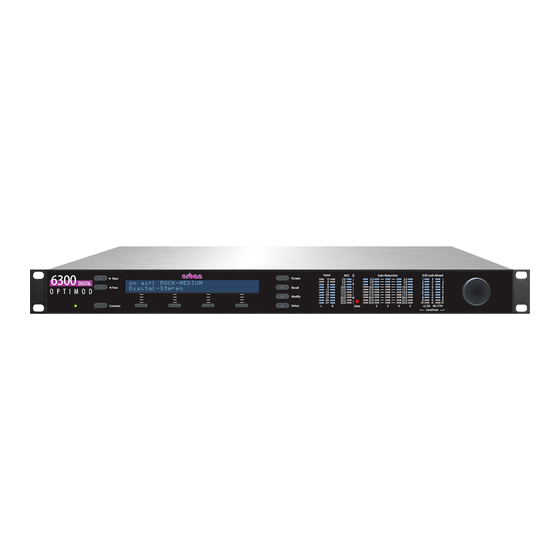
Page 143: Section 3 Operation
OPTIMOD 6300 DIGITAL OPERATION Section 3 Operation 6300 Front Panel Screen Display labels the four soft buttons and provides control-setting infor- mation. Screen Contrast button adjusts the optimum viewing angle of the screen dis- play. Four Soft buttons provide access to all 6300 functions and controls. The func-... - Page 144 OPERATION ORBAN MODEL 6300 Escape button provides an escape from current screen and returns user to the next higher-level screen. Repeatedly pressing Escape will always return you to the Idle screen, which is at the top level of the screen hierarchy.
- Page 145 OPTIMOD 6300 DIGITAL OPERATION the gain reduction of the Multiband output channel’s look-ahead lim- iters in units of dB; the action of the High Frequency Enhancer and Stereo Enhancer proc- essing, in arbitrary units. Newer 6300s have redesigned front-panel graphics that do not show scales for the Enhancers.
-
Page 146: Introduction To Processing
OPERATION ORBAN MODEL 6300 See also Figure 1-1: Simplified Block Diagram of Dialnorm Control on page 1-2. avoid having toggle meters between functions, we recommend using PC Remote for doing serious setup and tuning. Introduction to Processing Some Audio Processing Concepts Reducing the peak-to-average ratio of the audio increases loudness. -
Page 147: Loudness And Distortion
In processing, there is a direct trade-off between loudness and distortion. You can improve one only at the expense of one or both of the other two. Thanks to Orban’s psychoacoustically optimized designs, this is less true of Orban processors than of any others. -
Page 148: Speech/Music Detector
Speech that is not located in the center of the stereo sound field will always be de- tected as “music” because the detector always identifies stereo material as “music.” Optimod 6300 in Radio-Oriented Applications: From Bach to Rock The 6300 can be adjusted so that the output sounds: ... -
Page 149: Sound-For-Picture Applications: Controlling Dynamic Range
OPTIMOD 6300 DIGITAL OPERATION In professional broadcasting environments, you will achieve best results if Engineer- ing, Programming, and Management go out of their way to communicate and co- operate with each other. It is important that Engineering understand the sound that... -
Page 150: About The 6300'S Signal Processing Features
Multiband Compression in either two or five bands, depending on the proc- essing structure Automatic Loudness Control using Orban’s third-generation CBS Loudness Controller™ algorithm plus a BS.1770 Safety Limiter Look-Ahead Limiting A sample rate converter converts the sample rate at the digital input to the 6300’s internal 48 kHz rate. - Page 151 2-band Gated AGC: The AGC is a 2-band device, using Orban’s patented “master / bass” band coupling. It has an additional important feature: target-zone gating. If the input program material’s level falls within a user-settable window (typically 3dB), then the release time slows to a user-determined level.
- Page 152 3-10 OPERATION ORBAN MODEL 6300 enhancing bright material. It interacts synergistically with the 5-band compressor to produce sound that is bright and present without being excessively shrill. Multiband Compression: The multiband compressor can be operated in 5-band or 2-band mode. In 5-band mode, each band compressor has a K...
- Page 153 3-11 OPTIMOD 6300 DIGITAL OPERATION Unlike some familiar compressors and limiters (whose gain reduction is adjusted via threshold controls), the 6300 limiter’s threshold is fixed with respect to the input of the 6300’s digital output level control so the limiter’s drive level solely determines the gain reduction.
- Page 154 3-12 OPERATION ORBAN MODEL 6300 loudness controller from causing too much dynamic bass boost, you can use the OUDNESS ONTROLLER OUPLE control to limit the maximum difference be- tween the gain of the band below 200 Hz and the band above 200Hz. For example, when this control is set to 3 and the loudness controller’s gain reduction is 10 dB,...
-
Page 155: Bs.1770 Safety Limiter
3-13 OPTIMOD 6300 DIGITAL OPERATION preset, turn the Loudness Controller off, and then save the result as a User Preset. Using one of the 6300’s remote control mechanisms (like its GPI inputs), recall the “with loudness controller” and “without loudness controller” presets as desired. -
Page 156: 2-Band Purist Processing
3-14 OPERATION ORBAN MODEL 6300 ceeds 2 dB, and is indicated by the amber section of the L OUDNESS meter in 6300 PC Remote. The gain reduction produced by the CBS Loud- ness Controller may change slowly or quickly (depending on the nature of the program material), appears in cyan, and rides on top of the BS.1770 gain reduction. -
Page 157: Customizing The 6300'S Sound
Orban’s audio processing experts on the basis of years of experience designing audio processing and upon hundred of hours of listening tests. -
Page 158: Full Modify
“full con- trol” available in Orban’s 6200 processor. Because of improvements in the 6300’s sig- nal processing by comparison to the 6200, these controls are not extremely danger- ous (although you can still get into trouble if you try hard enough). -
Page 159: Gain Reduction Metering
Because the various compressors have 25 dB of gain reduction range, the meter should never come close to 25 dB gain reduction if OPTIMOD 6300 has been set up for a sane amount of gain reduction under ordinary program conditions. - Page 160 3-18 OPERATION ORBAN MODEL 6300 The instructions below describe how to correctly set the loudness of user presets that you create. You must use 6300 PC Remote for these adjustments. See To Create or Save a User Preset on page 2-19.
-
Page 161: To Create Or Save A User Preset
3-19 OPTIMOD 6300 DIGITAL OPERATION D) If the AGC’s idle gain (i.e. the gain reduction produced by the AGC when its si- lence gate is on) is inappropriate, adjust it with the AGC I control. If you are using a factory processing preset and you have adjusted the... -
Page 162: About The Processing Structures
3-20 OPERATION ORBAN MODEL 6300 B) Press the S RESET button. The Save Preset screen appears. C) Choose a name for your preset. Some non-alphanumeric characters (such as < and >) are reserved and cannot be used in preset names. - Page 163 Both the 2-band and 5-band multiband compressors always operate in the back- ground. Switching between 2-band and 5-band therefore occurs with a seamless cross-fade. Unlike some older Orban processors, no DSP code gets reloaded and no audio mute occurs, although switching can sound obtrusive if the loudness normally produced by the 2-band and 5-band presets are very different.
-
Page 164: Factory Programming Presets
3-22 OPERATION ORBAN MODEL 6300 2-band: The 2-band structure consists of a slow 2-band gated AGC (Automatic Gain Control) for gain riding, followed by a gated 2-band compressor and a look-ahead limiter. By choosing the crossover mode correctly, the 2-band Structure can be made phase-linear throughout to maximize sonic transparency. -
Page 165: Protection And Agc Presets
3-23 OPTIMOD 6300 DIGITAL OPERATION able by those with special, arcane knowledge that we withhold from most of our customers. Start with one of these presets. Spend some time listening critically to your sound. Listen to a wide range of program material typical of your format and listen on sev- eral types of audio systems (not just on your studio monitors). - Page 166 3-24 OPERATION ORBAN MODEL 6300 To produce look-ahead limiter gain reduction, turn up the L control. Each step of the L control increases the drive level to the look-ahead limiter by 1 dB and increases the input/output gain by 1 dB for signals below the limiter = 10, the processor’s gain below threshold has increased to...
-
Page 167: Radio-Style Presets
The presets (Table 3-2 on page 3-26) have been named similarly to their radio coun- terparts in Orban’s OPTIMOD-FM 8400 and 8500. The basic audio texture of corre- sponding 6300 and 8500 presets (heard through the 8500’s digital radio output) is similar, although the 6300 will tend to have 1-2 dB more bass. - Page 168 3-26 OPERATION ORBAN MODEL 6300 because the 6300 performs no high frequency limiting other than that created by gain reduction in Band 5 in the 5-band presets. RADIO-STYLE PRESETS Preset Names Source Preset Normal Less-More CLASSICAL-2 BAND CLASSICAL-2 BAND CLASSICAL-2B SFTKN...
- Page 169 OPTIMOD 6300 DIGITAL OPERATION Unlike the presets in Orban’s FM processors, no 6300 preset uses phase rotation. Therefore, if you use the 6300 to process the main digital chan- nel in HD Radio, some care must be applied in cross fading to avoid mo- mentary audible comb filtering because of the different phase responses of the analog and digital channels.
- Page 170 GREGG: GREGG and GREGG OPEN all use a 200 Hz band1/band2 crossover fre- quency to achieve a bass sound similar to the classic 5-band Gregg Labs FM proces- sors designed by Orban’s Vice President of New Product Development, Greg Ogonowski. Dynamically, these presets produce a slight increase in bass energy be- low 100 Hz and a decrease of bass energy centered at 160 Hz.
- Page 171 3-29 OPTIMOD 6300 DIGITAL OPERATION INSTRUMENTAL: An alias for the JAZZ preset. JAZZ: JAZZ is specifically tailored toward broadcasters that play mostly instrumental music, particularly classic “hard” jazz (Coltrane, Mingus, Monk, etc.). It is a quiet pre- set with a very clean, mellow high end to prevent stridency on saxes and other horns.
- Page 172 3-30 OPERATION ORBAN MODEL 6300 SPORTS: Similar to NEWS-TALK except the AGC Release (AGC Release Time) is slower and the Gate Thresh (Gate Threshold) is higher. This recognizes that most sports programming has very low signal-to-noise ratio due to crowd noise and other on-field sounds, so the preset does not pump this up as the NEWS-TALK preset would tend to do.
-
Page 173: Sound-For-Picture Presets
3-31 OPTIMOD 6300 DIGITAL OPERATION WMA MUSIC: This preset is based on GREGG SLOW but has been edited to mini- mize artifacts in the Windows Media Audio V9 codec when operated at bitrates be- low 64 kbps. See Processing for Low Bit Rate Codecs on page 3-5. - Page 174 The TVAxxx are tuned to produce the same loudness as the general purpose TV presets in Orban’s processors for analog aural carriers, such as Optimod-TV 8282 and 8382. Dialnorm is set to –17 dB, which facilitates this loudness match. See step (10.D) on page 2-25.
- Page 175 3-33 OPTIMOD 6300 DIGITAL OPERATION TV 5B GEN PURP –LC (TV Five-Band General Purpose Without Loudness Controller): This preset is the same as TV 5B-GEN PURPOSE except the Loudness Controller is turned off and the MB D control is backed off by 3 dB to achieve approximately RIVE the same loudness as TV 5B-GEN PURPOSE.
-
Page 176: Equalizer Controls
3-34 OPERATION ORBAN MODEL 6300 common in live news broadcasts). The dynamic single-ended noise reduction is turned on. TV 5B-SPORTS (TV Five-Band Sports): is similar to TV 5B-N , except the AGC re- lease time is slower to resist pumping up crowd noise. - Page 177 3-35 OPTIMOD 6300 DIGITAL OPERATION BASS SLOPE sets the slope ( dB/octave) of the transition between the top and bottom of the shelf. The moderate-slope (12 dB/octave) shelving boost achieves a bass boost that is more audible on smaller receivers, but which can sound boomier on high-quality receivers and home theater systems.
- Page 178 “mellowness” to the sound when boosting. When cutting, it can remove a “woody” or “boxy” sound. The equalizer, like the classic Orban analog parametrics such as the 622B, has con- stant “Q” curves. This means that the cut curves are narrower than the boost curves.
- Page 179 3-37 OPTIMOD 6300 DIGITAL OPERATION MID WIDTH determines the bandwidth of the equalization, in octaves. The range is 0.8-4.0 octaves. If you are unfamiliar with using a parametric equalizer, 1 octave is a good starting point. With 5-band presets, the audible effect of the midrange equalizer is closely associ- ated with the amount of gain reduction in the midrange bands.
- Page 180 The difference will never exceed the difference that would have other- wise occurred if the lowest frequency band were gated independently. If you are familiar with older Orban processors like the 8282, this is the maximum amount of boost that would have occurred if you had set their...
-
Page 181: Stereo Enhancer Controls
Stereo Enhancer Controls You can operate the stereo enhancer in one of two modes or “styles.” The first is called L–R E and emulates the Orban 222 analog stereo enhancer, while the XPAND second mode, called D ELAY , emulates a popular enhancer from another manufac- turer that adds a delayed version of the L–R signal to the original L–R to create ste-... -
Page 182: Agc Controls
3-40 OPERATION ORBAN MODEL 6300 the L-R / L+R Ratio Limit control. In this case, the enhancer prevents further enhancement in order to pre- vent excess L–R energy, which can increase multipath distortion. The stereo enhancer has the following controls: Amount sets the maximum spatial enhancement. - Page 183 OPTIMOD 6300 DIGITAL OPERATION are using a studio level controller (like Orban’s 8200ST). However, in this case it is better to defeat the AGC globally in System Setup. AGC DRIVE control adjusts signal level going into the slow dual-band AGC, there- fore determining the amount of gain reduction in the AGC.
- Page 184 AGC GATE (“AGC Gate Threshold”) control determines the lowest input level that will be recognized as program by OPTIMOD 6300; lower levels are considered to be noise or background sounds and cause the AGC or multiband compressor to gate, effectively freezing gain to prevent noise breathing.
-
Page 185: Advanced Agc Controls
3-43 OPTIMOD 6300 DIGITAL OPERATION AGC B CPL (“AGC Bass Coupling”) control clamps the amount of dynamic bass boost (in units of dB) that the AGC can provide. (In V1.0, the unit of measure was percent.) The AGC processes audio in a master band for all audio above approximately 200 Hz and a bass band for audio below approximately 200 Hz. - Page 186 3-44 OPERATION ORBAN MODEL 6300 AGC Ratio determines the compression ratio of the AGC. The compression ratio is the ratio between the change in input level and the resulting change in output level, both measured in units of dB. The 6300 compressor can be operated at a compression ratio as low as 2:1. This can add a sense of dynamic range and is mostly useful for subtle fine arts formats like classical and jazz.
- Page 187 3-45 OPTIMOD 6300 DIGITAL OPERATION This control works the same regardless of whether the AGC operates in left/right or sum / difference M modes, in both cases controlling the ATRIX maximum gain difference between the “channels.” Depending on the Matrix mode setting, the “channels” will handle left and right signals or will handle sum and difference signals.
-
Page 188: Distortion Control
Distortion Control The distortion control adjustments are common to the 2-band and 5-band structures except as noted in the descriptions on the following pages. Bass Clip threshold controls Orban’s patented embedded bass clipper. Note that The S control overrides the B... -
Page 189: The 2-Band Structure
3-47 OPTIMOD 6300 DIGITAL OPERATION spectrally sparse midrange material (like a singer) and listen for IM distortion in- duced by the bass’ pushing the midrange into the look-ahead limiter. Although the low-IM technology in the 6300’s look-ahead limiter substantially reduces this distor- tion, overdriving the limiter hard enough can still cause problems. -
Page 190: Customizing The Settings
3-48 OPERATION ORBAN MODEL 6300 The 2-band structure has an open, easy-to-listen-to sound that is similar to the source material if the source material is of good quality. We recommend using it when you want to preserve the spectral balance of the source material while not significantly increasing program density. - Page 191 3-49 OPTIMOD 6300 DIGITAL OPERATION 2B REL (“2B Release”) control determines how fast the 2-band compressor releases (and therefore how quickly loudness increases) when the level of the program mate- rial decreases. This release time only applies when the silence gate does not gate the 2-band Compressor.
- Page 192 2B GATE (“2B Gate Threshold”) threshold control determines the lowest input level that will be recognized as program material by OPTIMOD 6300; lower levels are con- sidered to be noise or background sounds and will cause the AGC or 2-band com- pressor to gate, effectively freezing gain to prevent noise breathing.
- Page 193 3-51 OPTIMOD 6300 DIGITAL OPERATION sounds and underscoring from being pumped up, while lower settings are more common with musical programming. BASS CPL (“2B Bass Coupling”) is used to set the balance between bass and the rest of the frequency spectrum.
-
Page 194: Advanced 2-Band Controls
3-52 OPERATION ORBAN MODEL 6300 prefer the more open sound of the 5-band compressor without additional loudness control. The loudness controller sidechain receives the output of the MB Limiter. Hence, the loudness controller responds accurately to all 6300 audio processing except look- ahead limiting, which is a peak limiting process whose gain reduction does not sig- nificantly affect subject loudness. - Page 195 3-53 OPTIMOD 6300 DIGITAL OPERATION BS.1770 Limiter Threshold sets the threshold of the BS.1770 safety limiter (in units of LK or LU) with respect to the active D IALNORM value. See BS.1770 Safety Limiter on page 3-13. 2B Master Compression Threshold sets the level where gain reduction starts to occur in the Master (above 200Hz) band of the 2-band Compressor.
-
Page 196: Nee Atio
3-54 OPERATION ORBAN MODEL 6300 HRESHOLD control affects the sound less and less. 2B Master Attack sets the attack time of the 2-band Compressor master compres- sor (above 200Hz). 2B Bass Attack sets the attack time of the 2-band Compressor bass compressor (be- low 200Hz). -
Page 197: The 5-Band Structure
3-55 OPTIMOD 6300 DIGITAL OPERATION ratio is less than infinite, the effective breakpoint of the compressor will be lower than 2B B setting. REAKPOINT The main use of the 2B B REAKPOINT control is to prevent the compressor from objec- tionably increasing audio density when using low compression ratios and a signifi- cant amount of gain reduction—for example, 10 dB. -
Page 198: Customizing The Settings
3-56 OPERATION ORBAN MODEL 6300 picture-oriented preset is on the air, the L control adjusts the average amount of gain reduction by adjusting the drive level to the 5-band structure's in- put. This also adjusts the idle gain—the amount of gain reduction in the AGC section when the structure is gated. - Page 199 3-57 OPTIMOD 6300 DIGITAL OPERATION trolled without adding excessive density to the audio or re-equalizing to an unnatu- ral extent. The M interacts with the M ULTIBAND RIVE ULTIBAND ELEASE . With slower release time settings, increasing the M control scarcely affects density. Instead, the...
- Page 200 (page 3-6). MB GATE (“Multiband Gate Threshold”) control determines the lowest input level that will be recognized as program by OPTIMOD 6300; lower levels are considered to be noise or background sounds and cause the AGC or multiband compressor to gate, effectively freezing gain to prevent noise breathing.
- Page 201 3-59 OPTIMOD 6300 DIGITAL OPERATION control sets the expansion threshold in Bands 1-4, while the B5 D XPANDER control (first introduced as part of V1.1 software) allows you to fine- ELTA HRESH tune the Band 5 downward expander’s threshold by adding or subtracting an offset...
- Page 202 3-60 OPERATION ORBAN MODEL 6300 Note also that it is virtually impossible to achieve undetectable dynamic noise reduc- tion of program material that is extremely noisy to begin with, because the program never masks the noise. It is probably wiser to defeat the dynamic noise reduction with this sort of material (traffic reports from helicopters and the like) to avoid ob- jectionable side effects.
-
Page 203: Advanced 5-Band Controls
3-61 OPTIMOD 6300 DIGITAL OPERATION (6.2 kHz and above) is determined by and follows the gain of band 4. The sum of the high frequency limiter control signal and the output of the B4>B5 determines the gain reduction in band 5. The B4>B5 CPL control re- CONTROL ceives the independent left and right band 4 gain control signal. - Page 204 3-62 OPERATION ORBAN MODEL 6300 B1-B5 Attack (Time); Speech B1-B5 Attack controls set the speed with which the gain reduction in each band responds to level changes at the input to a given band’s compressor for music and speech respectively, following the 6300’s automatic speech/music detector.
-
Page 205: Test Modes
3-63 OPTIMOD 6300 DIGITAL OPERATION Bx Breakpoint: See page 3-54. B1/B2 Crossover (Band 1 to Band 2 Crossover Frequency) sets the crossover fre- quency between bands 1 and 2 to either 100 Hz or 200 Hz. It significantly affects the bass texture and the best way to understand the differences between the two cross- over frequencies is to listen. -
Page 206: Using The 6300 Pc Remote Control Software
Before running 6300 PC Remote, you must have installed the appropriate Windows communications services on your computer. By default, the installer installs a short- cut to 6300PC.exe on your desktop and in your Start Menu under Orban\Optimod 6300. 6300 PC Remote can control only one 6300 at a time, but it can readily switch be- tween several 6300s. -
Page 207: To Initiate Communication
“Loading system files, please wait.” When run, the Orban PC Remote software installer makes copies of all 6300 fac- tory preset files on your local hard drive. The PC Remote software reads these files to speed up its initialization. -
Page 208: To Modify A Control Setting
3-66 OPERATION ORBAN MODEL 6300 A wheel mouse is the quickest and easiest interface to use—you will rarely (if ever) have to use the keyboard. The help box at the bottom of the screen always presents a short help mes- sage for the function you have selected. -
Page 209: To Back Up User Presets, System Files, And Automation Files Onto Your Computer's Hard Drive
The encryption options prevent archived presets, system files, and auto- mation files from being restored if the user does not have the password used for the encryption. There is no “back door”— Orban cannot help you to decrypt a preset whose password is unknown. -
Page 210: To Restore Archived Presets, System Files, And Automation Files
If the preset, system file, or automation file was encrypted when it was originally saved, PC Remote will request the password under which it was encrypted. All User Presets are compatible with all 6300 software versions. If Orban adds new controls to a software version, the new software will assign a reasonable default value to any control missing in an old User Preset. -
Page 211: To Modify Input / Output And System Setup
3-69 OPTIMOD 6300 DIGITAL OPERATION c) Click the R ESTORE button. E) To restore a system file: a) Set the F field to the System Setup file type (*.orb63setup). ILES b) Select the desired system file in the dialog box. -
Page 212: To Quit The Program
There are a few extra things to know if you have multiple installations. If you install a new version of the Optimod 6300 PC Remote software on your PC, any Alias folders and backup subfolders created in an earlier software version still remain in their original location on your PC (and in its registry). - Page 213 Do not use an external file manager (like Windows Explorer) to do this. The old Alias folders need to be re-created under the Optimod 6300 PC Remote software you wish to use (so that the registry entries can be correctly updated). You can do this two different ways.
-
Page 214: Using The 6300 For Production And Mastering
3-72 OPERATION ORBAN MODEL 6300 Backup directory that you wish to keep, you should therefore move that directory elsewhere (or transfer the desired files to another, active backup directory). Ordinarily, the erasure process will move the Backup directory to your computer’s Recycle Bin, so you can recover a Backup directory that you... - Page 215 3-73 OPTIMOD 6300 DIGITAL OPERATION 2-band and 5-band compressor/limiters with phase-linear crossovers and power- ful controls, including attack time, release time, threshold, knee, and ratio for each band. These compressor/limiters also offer user-adjustable inter-band cou- pling, allowing the user to operate them anywhere from quasi-wideband to fully independent.
- Page 216 3-74 OPERATION ORBAN MODEL 6300 If you are going to use 5-band processing, recall the 5 preset. If you want to do look-ahead peak limiting without any other dynamics processing, recall the L HEAD IMITER preset. See Protection and AGC Presets on page 3-23 for a description of these presets.
- Page 217 3-75 OPTIMOD 6300 DIGITAL OPERATION I) Adjust the A TTACK controls on the individual compressors to trade off overshoot control against transient punch. J) Adjust the R and K controls in each band to taste. ATIO The R ATIO control sets the compression ratio at the threshold of compres- sion.
- Page 218 3-76 OPERATION ORBAN MODEL 6300 Of course, sometimes pumping is desired for certain styles of music and/or recording. The L controls can help achieve this IMITER TTACK sound. N) Adjust the T control to taste. RANSIENT NHANCE This control allows you to insert an audio delay of up to 10 ms in the sidechain of the five-band compressor.
- Page 219 3-77 OPTIMOD 6300 DIGITAL OPERATION S) For a 44.1 or 88.2 kHz output sample rate, set the digital output level (step 11 on page 2-26) to approximately –0.5dBFS; this will prevent overshoots caused by sample rate conversion. For a 48 or 96 kHz output sample rate, set the digi- tal output level to –0.1dBFS.
- Page 220 3-78 OPERATION ORBAN MODEL 6300...
-
Page 221: Appendix A: Using The Itu Bs.1770 And Cbs Loudness Meters To Measure Loudness Controller Performance
CBS Loudness Meter For many years, Orban has used the Jones & Torick loudness controller and loudness measuring technology in its products for loudness control of sound for picture. De- The CALM Act applies only to U.S. -
Page 222: Comparing The Meters
Since first licensing the CBS algorithm and using it in its Optimod-TV 8182 in the early 1980s, Orban has continually refined and developed this technology. In the last 30+ years, audio processors from Orban and CRL using the CBS loudness controller have processed millions of hours of on-air television programming —... - Page 223 3-81 OPTIMOD 6300 DIGITAL OPERATION B S . 1 7 7 0 - 2 I n t e g r a t e d M e t e r ( G a t e d ; I n t e g r a t i o n T i m e = 1 0 s e c o n d s ) H i s t o g r a m o f B S .
- Page 224 OPERATION ORBAN MODEL 6300 B S . 1 7 7 0 - 2 I n t e g r a t e d M e t e r ( G a t e d ; I n t e g r a t i o n T i m e = 1 0 s e c o n d s ) H i s t o g r a m o f B S .
-
Page 225: Test Setup
TV 5B GEN PURPOSE preset. The digital output of the processor was applied to the digital input of an Orban 1101 soundcard, which was adjusted to pass the au- dio without further processing and to apply it to an Orban software-based loudness meter that simultaneously computes the BS.1770-2 Integrated loudness and CBS... -
Page 226: Results
Figure 3-5 and Figure 3-6 narrower than the scales in Figure 3-3 and Figure 3-4.) Both the loudness vs. time graphs and the histograms show the Orban 8685 controls loudness well, although the details of the meters’ indications are different. Both the BS.1770 and CBS measurements indicate that most of the data points are in a... -
Page 227: Problems With Low Peak-To-Rms Ratio Material
3-85 OPTIMOD 6300 DIGITAL OPERATION The peak CBS readings fit within a ±2 dB window. The BS.1770 readings also fit within a ±2 LK window except for four short intervals, which appear as low- probability outliers in the left side of the histogram. These intervals correspond to dialog without background music and in the author’s opinion illustrate a weakness... -
Page 228: Studies Indicating That Bs.1770 Is Inaccurate At Very Low Frequencies
BS.1770-2 “short-term” loudness is always limited to 0 LK.) Regarding this, Orban and Dolby Labs hold similar views. We believe that dialog is the most important element in most television audio and that listeners do not want to turn down their volume controls every time that un- derscoring or effects appear under the dialog. - Page 229 3-87 OPTIMOD 6300 DIGITAL OPERATION Lavoie tried to extend the BS.1770 algorithm to include the LFE channel by sum- ming the K-weighted LFE channel’s power into the current BS.1770 algorithm, where the gain is weighted for the fact that LFE channel receives a 10 dB gain boost on playback, per Dolby’s standards.
-
Page 230: Discussion And Conclusions
(or worse from the broadcaster’s point of view, to mute a commercial). Whether measured via the CBS or BS.1770 algorithms, the CBS loudness controller algorithm in Orban’s current products effectively controls subjective loudness to much better than this +2, –5 dB window. - Page 231 OPTIMOD 6300 DIGITAL OPERATION ingly, the CBS Loudness Controller in Orban products, which uses the CBS loudness metering algorithm as its core loudness reference, produces consistent and naturally balanced dialog levels regardless of the program material and mixing style. Unlike the BS.1770 meter, the CBS technology does not unnaturally penalize material hav-...
-
Page 233: Section 4 Maintenance
6300 is at fault. The troubleshooting information in Section 5 will help you determine if the problem is with OPTIMOD 6300 or is somewhere else in the station's equip- ment. -
Page 234: Subassembly Removal And Replacement
MAINTENANCE ORBAN MODEL 6300 Subassembly Removal and Replacement See page 6-23 for the Circuit Board Locator and Basic Interconnections diagram. 1. Removing the Top Cover: To access any internal board (including the display assembly), you must remove the top cover. - Page 235 EMI. If the power supply fails, please contact Orban Customer Service (custserv@orban.com) to obtain an exact replacement. A) Verify that the 6300 is disconnected from the AC line.
- Page 236 MAINTENANCE ORBAN MODEL 6300 D) Remove the plug that connects the power supply to the AC line socket. E) Unplug the cable connecting the output of the power supply to the I/O+DSP board. F) Using a hex nutdriver, remove the threaded standoff that supports the power supply’s insulating cover.
- Page 237 OPTIMOD 6300 DIGITAL MAINTENANCE d) Evenly tighten all eight screws to reattach the board assembly to the panel. D) Place the two side brackets over the captive screws located on each side of the front panel. Be sure that the large side of each bracket is oriented toward the rack-screw cutouts in the panel.
-
Page 238: Field Audit Of Performance
MAINTENANCE ORBAN MODEL 6300 Field Audit of Performance Required Equipment: Ultra-low distortion sine-wave oscillator / THD analyzer / audio voltmeter With verified residual distortion below 0.01%. Audio Precision System One, or similar high-performance system. The NAB Broadcast and Audio System Test CD is an excellent source of test signals when used with a high-quality CD player. - Page 239 OPTIMOD 6300 DIGITAL MAINTENANCE Note: All analog output measurements are taken with a 620 ±5% resistor tied be- tween pin 2 and 3 of the XLR connector. 1. Prepare the unit. A) Use the front panel controls to set the 6300's software controls to their de- fault settings, as follows.
- Page 240 The power supply is a module. In case of any power supply failure, the entire supply must be replaced by an exact replacement (available from Orban Service). Attempts to repair the supply on a component level and/or to replace the supply with a non-approved supply may compromise your Optimod’s compliance with...
- Page 241 OPTIMOD 6300 DIGITAL MAINTENANCE H) Using VR201, repeat steps (C) through (G) for the Right Analog Output. 4. Check frequency response of Analog I/O. A) Verify 6300 software controls are set to their default settings. [Refer to step (1.A) on page 4-7.] B) Be sure you are still in B mode [see step (3.F)].
- Page 242 4-10 MAINTENANCE ORBAN MODEL 6300 G) Repeat the above measurements for the right channel. Connect the oscillator to the right analog input and the distortion analyzer to the right analog out- put. H) Disconnect the oscillator and THD analyzer from the 6300.
- Page 243 PC through a null modem cable. See Networking and Remote Con- trol starting on page 2-46 (in particular, step 4 on page 2-48). 10. Return OPTIMOD 6300 to service. A) Remove the 620 resistors connected across the outputs.
-
Page 245: Section 5 Troubleshooting
OPTIMOD 6300 DIGITAL TROUBLESHOOTING Section 5 Troubleshooting Problems and Potential Solutions Always verify that the problem is not the source material being fed to the 6300, or in other parts of the system. RFI, Hum, Clicks, or Buzzes For good RFI resistance, always use balanced inputs and outputs. -
Page 246: Audible Distortion
TROUBLESHOOTING ORBAN MODEL 6300 Audible Distortion Make sure that the problem can be observed on more than one monitoring system and at several locations. Verify that the source material at the 6300's audio inputs is clean. Heavy processing can exaggerate even slightly distorted material, pushing it over the edge into unac- ceptability. -
Page 247: Gain Pumping When High Frequency Energy Is Present
STL may only be 70-75 dB. In this case, it is wise to use an Orban Studio AGC to perform the AGC function prior to the STL transmitter and to control the STL's peak modulation. This will optimize the signal-to-noise ratio of the entire transmission system. -
Page 248: Excessive Sibilance ("Ess" Sounds)
TROUBLESHOOTING ORBAN MODEL 6300 In applications where you are protecting a pre-emphasized link, if the 6300’s output is set to F in S > O YSTEM ETUP UTPUT , there will be no preemphasis unless it is supplied somewhere else in the system. This will cause very dull sound. -
Page 249: Sound Is Unexpectedly Quiet
OPTIMOD 6300 DIGITAL TROUBLESHOOTING Sound is Unexpectedly Quiet The CBS Loudness Controller and/or BS.1770 Safety Limiter may be turned on acci- dentally. Their threshold controls are located in the M page of the active ULTIBAND processing preset. To defeat them, set their threshold controls to OFF. -
Page 250: Commercials Too Loud In Sound For Picture Applications
TROUBLESHOOTING ORBAN MODEL 6300 Commercials too loud in sound for picture applications Make sure that the Loudness Controller is activated on the preset that you are using—the L control must not be set O (see page OUDNESS ONTROLLER HRESH 3-51) and is normally set to –10 dB. -
Page 251: A Bs.1770 Loudness Meter Indicates Higher Loudness Than Expected With Some Program Material
OPTIMOD 6300 DIGITAL TROUBLESHOOTING Once D is correct, be sure that your active preset is causing the 6300’s IALNORM OUDNESS AIN REDUCTION meter to indicate approximately 3 dB of gain reduction on normal dialog. Adjust its MB L control if it does not. When the loud-... -
Page 252: Troubleshooting Connections
TROUBLESHOOTING ORBAN MODEL 6300 visible as the yellow section of the L . See BS.1770 Safety Lim- OUDNESS METER iter on page 3-13 for a more detailed discussion. Connection Issues between the 6300 and a PC, Modem, or Net- work ... -
Page 253: You Cannot Access The Internet After Making A Direct Or Modem Connection To The 6300
OPTIMOD 6300 DIGITAL TROUBLESHOOTING A) Ensure that the modem cables and phone lines are connected properly. B) Check that you have entered the correct phone number for connection. C) Check that you have entered the passcode correctly on the 6300, and the passcode has also been entered correctly on your PC. - Page 254 A) Click “Start / Programs / Accessories / Communications / Network and Dialup Connections” to bring up the Network Connections screen. B) In the “Network Connections” window, right-click “Optimod 6300 - Direct” and choose “Properties.” C) The “Properties” window opens for “Optimod 6300 - Direct D) Click the “Networking”...
-
Page 255: Troubleshooting Windows 2000 Modem Connect
A) Click “Start / Programs / Accessories / Communications / Network and Dialup Connections” to bring up the Network Connections screen. B) In the “Network Connections” window, right-click “Optimod 6300 - Modem” and choose “Properties.” C) The “Properties” window opens for “Optimod 6300 – Modem.”... -
Page 256: Troubleshooting Windows Xp Direct Connect
A) Click “Start / Programs / Accessories / Communications / Network Connections” to bring up the Network Connections screen. B) In the “Network Connections” window, right-click “Optimod 6300 - Direct” and choose “Properties.” C) The “Properties” window opens for “Optimod 6300 - Direct.”... -
Page 257: Troubleshooting Windows Xp Modem Connect
OPTIMOD 6300 DIGITAL TROUBLESHOOTING L) Click “OK” to dismiss the “Advanced TCP/IP Settings” window. M) On the “Properties” window for “Optimod 6300 – Modem” click the “Ad- vanced” tab. N) Click “OK” to dismiss the window whose name is your new connection. -
Page 258: Technical Support
Technical Support If you require technical support, contact Orban customer service. Be prepared to de- scribe the problem accurately. Know the serial number of your 6300 this is printed on the rear panel of the unit. Current contact information is found at http://www.orban.com/contact/. - Page 259 Returned units will be returned C.O.D. if the unit is not under warranty. Orban will pay return shipping if the unit is still under warranty. In all cases, the customer pays transportation charges to the factory (which are usually quite nominal).
-
Page 261: Specifications
OPTIMOD 6300 DIGITAL TECHNICAL DATA Section 6 Technical Data Specifications It is impossible to characterize the listening quality of even the simplest limiter or compressor based on specifications, because such specifications cannot adequately describe the crucial dynamic processes that occur under program conditions. There- fore, the only way to evaluate the sound of an audio processor meaningfully is by subjective listening tests. - Page 262 TECHNICAL DATA ORBAN MODEL 6300 Delay: The minimum available input/output delay is approximately 20 ms with look-ahead limiting active and 6 ms with look-ahead limiting bypassed. This can be padded to ex- actly one frame of 24, 25, 29.97, or 30 frames / second video up to a maximum delay of 50 ms.
- Page 263 OPTIMOD 6300 DIGITAL TECHNICAL DATA Analog Audio Output Configuration: Stereo. Flat or pre-emphasized (at 50µs or 75µs), software-selectable. Source Impedance: 50, electronically balanced and floating. Load Impedance: 600 or greater, balanced or unbalanced. Termination not required or recommended. Output Level (100% peak modulation): Adjustable from –6 dBu to +24 dBu peak, into 600...
- Page 264 TECHNICAL DATA ORBAN MODEL 6300 Termination: Unterminated. For wordclock, use an external 75 terminator if the 6300 is the last item in the chain. For AES11id, always use a 75 terminator. Remote Computer Interface Configuration: TCP/IP protocol via direct cable connect, modem, or Ethernet interface.
-
Page 265: Control Circuits
OPTIMOD 6300 DIGITAL TECHNICAL DATA Warranty Two Years, Parts and Service: Subject to the limitations set forth in Orban's Standard Warranty Agreement. Because engineering improvements are ongoing, specifications are subject to change with- out notice. Circuit Description This section provides a detailed description of user-serviceable circuits used in the 6300. -
Page 266: User Control Interface And Lcd Display Circuits
TECHNICAL DATA ORBAN MODEL 6300 The flash memory holds the operating system, the Orban executable program, and all preset files, both factory and user. It also contains a write-protected “boot seg- ment” that functions as a boot ROM. The control circuits process and execute user-initiated requests to the system. The source of these requests is the front panel buttons and rotary encoder, the rear panel RS-232 port, Ethernet port, and the remote contact closures. - Page 267 OPTIMOD 6300 DIGITAL TECHNICAL DATA Component-Level Description: After being current limited by resistors, the GPI control signals are applied to two quad optoisolators, U17, 19, and then to the control circuitry. U12 is the RS323 port interface chip. It is socketed for easy field replacement in the event of overload, lightning damage, etc.
-
Page 268: Input Circuits
TECHNICAL DATA ORBAN MODEL 6300 Input Circuits This circuitry interfaces the analog and digital inputs to the DSP. The analog input stages scale and buffer the input audio level to match it to the analog-to-digital (A/D) converter. The A/D converts the analog input audio to digital audio. The digi- tal input receiver accepts AES3-format digital audio signals from the digital input connector and sample rate-converts them as necessary. -
Page 269: Output Circuits
OPTIMOD 6300 DIGITAL TECHNICAL DATA 2. Stereo Analog-to-Digital (A/D) Converter Located on input/output/DSP board The A/D converter, IC107, is a stereo 24-bit sigma-delta converter. (This is a sur- face-mount part and is not field-replaceable,) The A/D oversamples the audio, applies noise shaping, and emits a bitstream at 48 kHz sample rate. -
Page 270: Dsp Circuit
6-10 TECHNICAL DATA ORBAN MODEL 6300 right analog output connectors. These analog signals can represent either the transmitter or monitor output of audio processing. Component-Level Description: IC201 and associated components filter the left channel signal emerging from IC211. The purpose of these stages is to reduce the out-of-band noise energy resulting from the delta-sigma D/A’s noise-shaping filter and to translate the... -
Page 271: Power Supply
During system initialization, the SC520 queries the DSP hardware about its opera- tional status and will display an error message on-screen if the DSP fails to initialize normally. Please note any such messages and be ready to report them to Orban Cus- tomer Service. - Page 272 6-12 TECHNICAL DATA ORBAN MODEL 6300 composite isolation transformer CMOS complementary metal-oxide semiconductor COFDM Coded Orthogonal Frequency Division Multiplex—a robust type of digital modulation using many narrow-bandwidth, low data rate, mutually non-interfering carriers to achieve an ag- gregate high data rate with excellent multipath rejection.
- Page 273 6-13 OPTIMOD 6300 DIGITAL TECHNICAL DATA random-access memory resistor / capacitor RDS / RBDS Radio (Broadcasting) Data Service—a narrowband digital subcarrier centered at 57 kHz in the TV baseband that usually provides program or network-related data to the consumer in the form of text that is displayed on the radio.
-
Page 274: Parts List
Consult the factory if the listing of a part includes the note “selected” or “realignment required.” Orban normally maintains an inventory of tested, exact replacement parts that can be supplied quickly at nominal cost. Standardized spare parts kits are also available. - Page 275 6-15 OPTIMOD 6300 DIGITAL TECHNICAL DATA Control Board PART # DESCRIPTION COMPONENT IDENTIFIER 20130.475.01 RESISTOR, 4.75K, 0805 (R36, NO, STUFF), R205, R207, R209, R211, R213, R215, R217 20130.562.01 RESISTOR, 1/8W, 1%, 5.62K, 0805 20131.100.01 RESISTOR, 10K, 0805 R1, R2, R9, R33, R37, R38, R39, 20131.113.01...
- Page 276 6-16 TECHNICAL DATA ORBAN MODEL 6300 Control Board PART # DESCRIPTION COMPONENT IDENTIFIER 24972.520.01 IC MICROPROCESSOR ELANSC520 BGA388 24979.000.01 IC, BAT54C-7 CR11, CR12 24983.000.01 IC, 7064STC100-10 25008.000.01 IC, PS2506-4 * U17, U19 27017.009.01 CONNECTOR, RT AGL, PC MNT, 9P 27017.025.01 CONNECTOR, RT AGL, PC MNT, 25P 27147.124.01...
- Page 277 6-17 OPTIMOD 6300 DIGITAL TECHNICAL DATA I/O+DSP BOARD PART # DESCRIPTION COMONENT IDENTIFIER 20128.022.01 RESISTOR 22 Ω 1% 0805 R806, R807, R808, R809, R810, R811, R813, R820 20128.075.01 RESISTOR, 75Ω, 1%, 0805 R158, R303 20129.100.01 RESISTOR, 100 Ω, 0805 R257, R258, R259, R260 20129.110.01...
- Page 278 6-18 TECHNICAL DATA ORBAN MODEL 6300 I/O+DSP BOARD PART # DESCRIPTION COMONENT IDENTIFIER C1012, C1013 21140.000.01 CAPACITOR, NPO, 470PF, 1%, 0805 C217, C218, C219, C220 21141.000.01 CAPACITOR, NPO, 1000PF, 1%, 0805 C236, C237, C238, C239, C305 21142.000.01 CAPACITOR, NPO, 100PF, 1%, 0805 C989 21143.000.01...
- Page 279 6-19 OPTIMOD 6300 DIGITAL TECHNICAL DATA I/O+DSP BOARD PART # DESCRIPTION COMONENT IDENTIFIER 27421.010.01 CONNECTOR, HEADER, DBL RW, 23", J800, J903 2 X 5 27426.003.01 CONNECTOR, HEADER, 3 PIN, SINGLE J801 27451.009.01 HEADER STR DBLRW 60P PCMT J701 27630.001.01 JUMPER, PC MNT, TEST POINT...
- Page 280 6-20 TECHNICAL DATA ORBAN MODEL 6300 Display Board (Back) PART # DESCRIPTION COMPONENT IDENTIFIER 42007.100 FLAT CABLE 26P 10" JP203 15065.355.01 LED-MNT-1 POS-0.355 FOR, CR1 USE 2 20122.110.01 RESISTOR, TF, 1/8W, 1%, 110 ohm R17, R18, R19, R20, R21, R22, R23, 20124.100.01...
- Page 281 6-21 OPTIMOD 6300 DIGITAL TECHNICAL DATA Function Description Drawing Page 6-23 Chassis Circuit Board Locator and Basic In- Top view terconnections (not to scale) 6-24 Control microprocessor. Services Parts Locator Control board front panel, serial port, Ethernet, Drawing and DSP+I/O board.
- Page 283 6-23 OPTIMOD 6300 DIGITAL TECHNICAL DATA WARNING: INPUT/OUTPUT PARTS SECTION UNDER SHIELD ARE EXPOSED TO AC LINE CONTROL INPUT/OUTPUT+DSP BOARD BOARD POWER SUPPLY DSP SECTION DISPLAY ASSEMBLY...
- Page 284 6-24 TECHNICAL DATA ORBAN MODEL 6300 CONTROL BOARD PARTS LOCATOR...
- Page 285 6-25 OPTIMOD 6300 DIGITAL TECHNICAL DATA C44 10UF +3.3V 10.0K 0.1UF SYSTEM_RESET-N (SHT 5) U5 MIC8115TU +3.3V U1B SC520 MR-n PIO14/GPIRQ9 RESET-n PWRGOOD PIO14/GPIRQ9 AC22 GP_RESET GPRESET PRGRESET PRGRESET MCP120-475I/TT 10.0K (SHT 5) 7x 4.75K DACK1-N PIO11/GPDACK1 AF10 DREQ1 PIO7/GPDRQ1...
- Page 286 6-26 TECHNICAL DATA ORBAN MODEL 6300 MD[0..31] MA[0..12] U2A MT48LC16 U3A MT48LC16 U1A SC520 MA12 MA12 MD15 MA12 MD31 MA12 DQ15 DQ15 MA11 MA11 MD14 MA11 MD30 MA11 DQ14 DQ14 MD31 MA10 +3.3V MA10 MD13 MA10 MD29 MD31 MA10 A10/AP...
- Page 287 6-27 OPTIMOD 6300 DIGITAL TECHNICAL DATA +3.3V PCI_AD[0..31] RNET4.7K +3.3V U1C SC520 U10A DP83816AVNG +3.3V PCI_AD31 PCI_AD31 REQ4 AD31 AD31 PCI_AD30 PCI_AD30 REQ3 AD30 AD30 PCI_AD29 PCI_AD29 REQ2 AD29 AD29 PCI_AD28 PCI_AD28 REQ1 AD28 AD28 PCI_AD27 PCI_AD27 AD27 AD27 PCI_AD26...
- Page 288 6-28 TECHNICAL DATA ORBAN MODEL 6300 PWRGOOD +3.3V (SHT2) +3.3V 100K 100K 100K 0 OHM U1D SC520 (NO-STUFF) 4.75K AF25 AC13 TRIG/TRACE TRIG/TRACE AF23 AD24 BR/TC BR/TC AE21 JTAG_TMS JTAG_TMS AE25 AF21 JTAG_TDI JTAG_TDI AE24 AD21 JTAG_TCK JTAG_TCK AD26 PIO31/RING2-N...
- Page 289 6-29 OPTIMOD 6300 DIGITAL TECHNICAL DATA +3.3V U10B DP83816AVNG +3.3V +3.3V (NO-STUFF) +3.3V U2B MT48LC16 U3B MT48LC16 U4B E28F128 C201 RESERVED 1.0UF RESERVED RESERVED +3.3V VCCQ VSSQ VDDQ VSSQ VDDQ VSSQ VDDQ VSSQ VDDQ VSSQ VDDQ VSSQ VDDQ VSSQ VDDQ...
- Page 290 6-30 TECHNICAL DATA ORBAN MODEL 6300 I/O+DSP BOARD PARTS LOCATOR...
- Page 291 6-31 OPTIMOD 6300 DIGITAL TECHNICAL DATA LEFT ANALOG INPUT +15V R130 R131 J100 FEMALE L100 IC100A 3.65K 1.50K FILTER 0.1% R100 L101 R101 OPA2134PA C108 E101 1200µH ????? C101 47PF 1000PF C100 47PF 5%,100V -15V 5%,100V R132 C132 R159 IC104B...
- Page 292 6-32 TECHNICAL DATA ORBAN MODEL 6300 LEFT ANALOG OUTPUT (6300) ANALOG OUTPUT 1 (9300) L204 +5VA J201 L200 MALE C201 FILTER 1.0µF R253 R257 C232 1.0µF L208 ????? 1000PF Servo R261 C203 C236 C240 f-3dB = 0.10Hz 0.1µF +15V C233 0.1µF...
- Page 293 6-33 OPTIMOD 6300 DIGITAL TECHNICAL DATA E313 PICSDI (SHT8) AES/EBU AESINCS-N (SHT8) DIGITAL INPUT R301 49.9K AESINLRCK (SHT5) J300 L300 FEMALE AESINSCLK (SHT5) C300 PICSCK (SHT8) T300 IC300 IC302 R300 PICSDO (SHT8) FERRITE SC937-02 SDA/CDOUT SCL/CCLK ????? 0.1µF 110OHM MMODE_2...
- Page 294 6-34 TECHNICAL DATA ORBAN MODEL 6300 IC400 IC403 AES/EBU DIGITAL PICSDI PICSCK OUTPUT 1 IC410A MMODE_2 (SHT8) SDA/CDOUT SCL/CCLK (SHT8) IC409A IC410B J400 L400 MCLK_C AESOUT1CS-N PICSDO (SHT9) MCLK_IN MMODE_1 (SHT8) AD0/CS AD1/CDIN (SHT8) MALE R400 T400 74ACT32 MCLK_OUT MMODE_0...
- Page 295 6-35 OPTIMOD 6300 DIGITAL TECHNICAL DATA E34 E35 IC501A IC502A IC503A IC504A E36 E37 DSP56367-150 DSP56367-150 DSP56367-150 DSP56367-150 SD03 SD32 (SHT9) SDI0 SDO0 SDI0 SDO0 SDI0 SDO0 SDI0 SDO0 (SHT9) SD04 SD33 (SHT9) SDI1 SDO1 SDI1 SDO1 SDI1 SDO1 SDI1...
- Page 296 6-36 TECHNICAL DATA ORBAN MODEL 6300 IC501C IC502C IC503C IC504C DSP56367-150 DSP56367-150 DSP56367-150 DSP56367-150 AA0/RAS0 AA0/RAS0 AA0/RAS0 AA0/RAS0 AA1/RAS1 AA1/RAS1 AA1/RAS1 AA1/RAS1 AA2/RAS2 AA2/RAS2 AA2/RAS2 AA2/RAS2 SSI_DO (SHT8) SSI_DI (SHT8) SSI_CLK (SHT8) DSPEN0-N DSPEN1-N DSPEN2-N DSPEN3-N (SHT8) (SHT8) (SHT8) (SHT8)
- Page 297 6-37 OPTIMOD 6300 DIGITAL TECHNICAL DATA IC702 74LVX4245 +3.3V IC703 C700 PIC16C67-20L IC700 0.1µF E712 ISA_D[0..7] E713 E714 E703 (SHT4) RD0/PSP0 RC0/T1OSO/T1CKI E704 IORD-N E715 B to A ADRST-N RD1/PSP1 RC1/T1OSI/CCP2 E705 ISA_D0 DSP_BUSEN-N (SHT9) DARST-N RD2/PSP2 RC2/CCP1 ISA_D1 (SHT9)
- Page 298 6-38 TECHNICAL DATA ORBAN MODEL 6300 +3.3V +3.3V +3.3V JTAG PORT +3.3V IC807G R816 R817 R818 IC800 74ACT04D 100.0K 100.0K 100.0K C809 +3.3V VCCINT 0.1µF J800 VCCINT VCCIO VCCIO VCCIO VCCIO VCCIO HDR 5X2 VCCIO UNSHRD +3.3V IC804A IC807E C804...
- Page 299 6-39 OPTIMOD 6300 DIGITAL TECHNICAL DATA FROM POW ER SUPPLY TO CONTROL COMBO PCA TP902 (NO-STUFF) TP-DUAL J900 J901 C946 10µF C1003 C1004 C947 C948 C949 C950 C951 C952 C953 C954 C955 C956 C957 C958 C959 + C995 C996 0.1µF 0.1µF...
- Page 300 6-40 TECHNICAL DATA ORBAN MODEL 6300 FRONT VIEW REAR VIEW FRONT PANEL PARTS LOCATOR DIAGRAM...
- Page 301 6-41 OPTIMOD 6300 DIGITAL TECHNICAL DATA CR1A CR1B CR1C CR1D CR1E CR1F CR1G CR1H CR1I CR1J CR2A CR2B CR2C CR2D CR2E CR2F CR2G CR2H CR2I CR2J CR3A CR3B CR3C CR3D CR3E CR3F CR3G CR3H CR3I CR3J CR4A CR4B GNDF T O GND PLA NE ON LY...
- Page 302 6-42 TECHNICAL DATA ORBAN MODEL 6300 RP 2 IC7C IC7F 74HC14A 74HC14A IC7D RES_NET 74HC14A D[0..7] D[0..7] 100 OHM 74AC574 74FCT574 IC7E DI SROW A DI SCOL B FY10 FY11 74HC14A FY12 FY13 SPARES 47PF FY14 FY15 8x2 POSTS 8x2 POSTS...
- Page 303 6-43 OPTIMOD 6300 DIGITAL TECHNICAL DATA...
Need help?
Do you have a question about the OPTIMOD 6300 and is the answer not in the manual?
Questions and answers