Table of Contents
Advertisement
Quick Links
Advertisement
Table of Contents
Troubleshooting

Related Manuals for Orban OPTIMOD-FM 5700i


Summary of Contents for Orban OPTIMOD-FM 5700i
- Page 1 Operating Manual OPTIMOD-FM 5700i Digital Audio Processor Version 2.1 Software...
- Page 2 European Parliament, this product must not be discarded into the municipal waste stream in any of the Member States. This product may be sent back to your Orban dealer at end of life where it will be reused or recycled at no cost to you.
- Page 3 IMPORTANT SAFETY INSTRUCTIONS All the safety and operating instructions should be read before the appliance is operated. Retain Instructions: The safety and operation instructions should be retained for future reference. Heed Warnings: All warnings on the appliance and in the operating instructions should be adhered to. Follow Instructions: All operation and user instructions should be followed.
- Page 4 Safety Instructions (German) Gerät nur an der am Leistungsschild vermerkten Spannung und Stromart betreiben. Sicherungen nur durch solche, gleicher Stromstärke und gleichen Abschaltverhaltens ersetzen. Sicherungen nie überbrücken. Jedwede Beschädigung des Netzkabels vermeiden. Netzkabel nicht knicken oder quetschen. Beim Abziehen des Netzkabels den Stecker und nicht das Kabel enfassen.
- Page 5 (2) Check the other sections of the Manual (consult the Table of Contents and Index) to see if there might be some sug- gestions regarding your problem. (3) After reading the section on Factory Assistance, you may call Orban Customer Service for advice during normal Ari- zona business hours. The number is +1 856.719.9900...
- Page 6 This manual was published November 2018. © Copyright Orban. This manual may be freely printed out and distributed if this copyright notice is not removed. However, no derivative works may be made from the contents of this manual without written permission from Orban.
- Page 7 Operating Manual OPTIMOD-FM 5700i Digital Audio Processor Version 2.1 Software...
-
Page 8: Table Of Contents
Table of Contents Index.........................0-9 Section Introduction ............................1-1 .......................1-1 BOUT THIS ANUAL OPTIMOD-FM 5700 ............1-1 IGITAL UDIO ROCESSOR User-Friendly Interface....................1-2 Absolute Control of Peak Modulation..............1-3 Flexible Configuration ....................1-4 Adaptability through Multiple Audio Processing Structures .......1-6 ... - Page 9 Circuit Ground .......................2-12 ) ............2-12 TUDIO EVEL ONTROLLER NSTALLATION OPTIONAL If you are using Orban 8200ST external AGC ............2-12 Figure 2-4: 8200ST Jumper Settings (*Factory Configuration) ........2-13 .........................2-15 UICK ETUP I/O S ..................2-26...
- Page 10 Installing the Necessary Windows Services............2-58 Check Hardware Requirements................2-58 Running the Orban Installer Program ..............2-59 Setting Up Ethernet, LAN, and VPN Connections ..........2-60 Conclusion......................2-60 .............2-61 PPENDIX ETTING ERIAL OMMUNICATIONS Preparing for Communication through Null Modem Cable ......2-61 ...
- Page 11 Two-Band Purist Processing ..................3-13 Digital Radio Processing..................3-13 BS.1770 Compliance for Digital Radio ..............3-14 Input/Output Delay ....................3-14 5700 ’ ...................3-15 USTOMIZING THE OUND Basic Modify......................3-15 Advanced Modify ....................3-16 Gain Reduction Metering ..................3-17 To Create or Save a User Preset ................3-17 ...
- Page 12 .........................3-77 ODES Table 3-13: Test Modes ....................3-77 ................3-78 ETTING THE OUND Summary ......................... 3-80 5700 PC R ............3-80 SING THE EMOTE ONTROL OFTWARE To set up a new connection:.................3-81 To initiate communication:...................3-81 ...
- Page 13 Talent Complains About Delay in Their Headphones............. 5-6 HD Output Sounds Too Bright ..................5-6 Harsh Sibilance (“Ess” Sounds) in the HD Channel ............5-7 HD and FM Levels Do Not Match When the Receiver Crossfades ........5-7 Digital Radio Loudness Cannot be Set Using the Digital Output 100% Peak Level ...
- Page 14 Function Description Drawing Page Chassis Circuit Board Locator and Basic In- Top view 6-27 terconnections (not to scale) Control board Control microprocessor. Services Parts Locator 6-28 front panel, serial port, Ethernet, Drawing and DSP+I/O board. Contains: General Purpose bus, address de- Schematic 1 of 5 6-29 coder, I/O+DSP interface...
-
Page 15: Index
Index Analog delay remote control 2- · 44 analog fallback 2- · 28 analog I/O 1- · 10 19 K Ref control 2- · 10 analog input circuit description 6- · 9 ref level, I/O setup 2- · 26 analog input 2- · 6 analog landline 1- ·... - Page 16 Multiband 3- · 58 activate via GPI 2- · 43 Bandwidth Setting HD 3- · 67 base board removing 4- · 3 cable replacing 4- · 4 shielding 2- · 11 baseband spectrum 5- · 4 type recommended for analog I/O 2- · 5 Baseband spectrum diagram 3- ·...
- Page 17 pilot tone protection 2- · 9 AGC 3- · 37 Composite meter 3- · 2 Band 1 / Band 2 3- · 62 composite output cable specification 2- · 9 I/O setup 2- · 20, 29 impedance 2- · 8 D/A converter level adjustment range 2- ·...
- Page 18 control via GPI 2- · 44 Pilot Protection 3- · 43 diversity delay 2- · 30, 31, 38 final clip drive 3- · 41 diversity delay 3- · 67, 75 Final clipper diversity delay 5- · 2 Defeating 2- · 28 Firewall 2- ·...
- Page 19 power 2- · 11 grounding 2- · 11 grouping 5700s 3- · 86 AES/EBU 2- · 7 connections 2- · 2 I/O board replacing 4- · 4 Half-cosine interpolation limiter 3- · 11, IC opamps troubleshooting 5- · 14 Hard Clip Shape 3- · 41 Idle Gain 3- ·...
- Page 20 deemphasis applied to digital audio input 6- NICAM 1- · 18 · 3 used in STLs · 17 loudness defined 1- · 10 preemphasis applied to digital audio output insufficient 5- · 7 6- · 3 insufficient due to poor peak control 5- · 1 Jazz format 3- ·...
- Page 21 5- · 3 recovering from lost 2- · 42 null modem cable communicating through 2- · 61 Orban installer program 2- · 59 null modem cable 2- · 58 PC board locator diagram 6- · 27 PC control security 1- · 28 PC hardware requirements 2- ·...
- Page 22 PuTTY power supply direct control using 2- · 48 circuit description 6- · 13 PuTTY 6- · 49 Orban part # 6- · 14 testing 4- · 7 power supply board reattaching 4 · 4 pre-emphasis quick setup 2- · 15 defeating 2- ·...
- Page 23 terminal timeout 2- · 104 composite meter does not indicate 1- · 23 timeout 2- · 102 input, specifications 6- · 4 RDS -2 · 97 inputs 1- · 11 interference from stereo 5- · 4 rear panel 2- · 4 modulation reduction 2- ·...
- Page 24 quick setup 2- · 15 spectrum analyzer 4- · 6 System Setup screen 2- · 15 Speech Detect control 3- · 9 Speech Mode forcing 3- · 63 speech mode 3- · 9 speech/music detector Talk format 3- · 25 overriding 3- ·...
- Page 25 Two-band structure 3- · 19 warranty 6- · 6 whistle on-air troubleshooting 5- · 4 Window Release 3- · 36 Window Size 3- · 35 Ultra-low Latency Windows and clipping distortion controller 3- · 9 installing services 2- · 58 and compressor look-ahead 3- ·...
-
Page 27: Section 1 Introduction
Because OPTIMOD-FM incorporates several audio processing innovations exclusive to Orban products, you should not assume that it can be operated in the same way as less sophisticated processors. If you do, you may get disappointing results. -
Page 28: User-Friendly Interface
If you wish to place level protection prior to your studio / transmitter link (STL), use the Orban Optimod 6300 or Optimod-PC 1101 or 1101e. These processors can be ad- justed so that they substitute for the AGC circuitry in OPTIMOD-FM, which is then defeated. -
Page 29: Absolute Control Of Peak Modulation
OPTIMOD-FM DIGITAL INTRODUCTION Absolute Control of Peak Modulation • The 5700i provides universal transmitter protection and audio processing for FM broadcast. It can be configured to interface ideally with any commonly found transmission system in the world, analog or digital. •... -
Page 30: Flexible Configuration
• OPTIMOD-FM 5700i is supplied with analog and AES3 digital inputs and outputs. The digital input and the two digital outputs are equipped with sam- ple-rate converters and can operate at 32 kHz, 44.1 kHz, 48 kHz, 88.1 kHz, and 96 kHz sample rates. - Page 31 FM exciter. Both the 5700i and 5700iFM offer this feature, making it con- venient to use the 5700iFM in dual-processor HD installations where the digital channel receives independent processing from a processor like Orban’s Optimod- DAB or Optimod-PC. Each output (Analog, Digital 1, Digital 2, Composite) can be independently configured to emit the delayed or undelayed signal.
-
Page 32: Adaptability Through Multiple Audio Processing Structures
A special Two-Band preset creates a no-compromise “Protect” function that is functionally similar to the “Protect” structures in earlier Orban digital processors. • The 5700i can increase the density and loudness of the program material by multiband compression, limiting, and clipping—improving the consistency of the... -
Page 33: Upgradeable To 8600S
Via a purchased upgrade kit, the 5700i can be upgraded to full 8600S func- tionality via a network connection without removing the unit from the rack. This upgrade adds Orban’s exclusive MX limiter technology, which uses a built-in psychoacoustic model and other advanced signal processing techniques to add about 2.5 dB more high frequency power handling capability, lower distortion,... -
Page 34: Factory Presets
INTRODUCTION ORBAN MODEL 5700i Factory Presets The Factory Presets are our “factory recommended settings” for various program formats or types. The description indicates the processing structure and the type of processing. Each Factory Preset on the Preset list is really a library of more than 20... -
Page 35: Input/Output Configuration
OPTIMOD-FM DIGITAL INTRODUCTION Input/Output Configuration The 5700i offers: • One digital AES left/right input on XLR that can also be used as a sync reference to lock the digital output sample rate and the 19 kHz pilot tone frequency. • One AES3id input on BNC that can be used as an audio input in “ratings en- coder Loopthrough mode.”... -
Page 36: Analog Left/Right Input/Output
1-10 INTRODUCTION ORBAN MODEL 5700i Level control of the AES3 input is accomplished via software control through System Setup (see step 5 on page 2-28) or through PC Remote. Both analog and digital outputs are active continuously. The 5700i’s output sample rate and 19 kHz pilot tone frequency can be locked to the 5700i’s internal crystal clock, to the sample rate present at its AES3 input, or to a... -
Page 37: Subcarriers
1-11 OPTIMOD-FM DIGITAL INTRODUCTION Subcarriers The stereo encoder has two unbalanced 600Ω subcarrier (SCA) inputs with rear- panel BNC connectors to accept any subcarrier at or above 23 kHz. The subcarriers are mixed into each composite output and their level is not affected by the compos- ite level control for that output. -
Page 38: Computer Interface
1-12 INTRODUCTION ORBAN MODEL 5700i The remote control of overshoot compensation and SCA modulation (see page 2-43) is not latching. You must supply a continuous current to the programmed remote input to hold the gain at its compensated level. Use... -
Page 39: Rj45 Ethernet Connector
1-13 OPTIMOD-FM DIGITAL INTRODUCTION RJ45 Ethernet Connector The 5700i can be connected to a 10, 100, or 1000 Gb/sec Ethernet network that sup- ports the TCP/IP protocol and is connected via CAT5 or CAT6 cabling. See Networking and Remote Control on page 2-44 for more information. Wordclock/10 MHz Sync Reference Input The sync reference input appears on a female BNC jack grounded to the 5700i’s chassis. -
Page 40: Best Location For Optimod-Fm
1-14 INTRODUCTION ORBAN MODEL 5700i 1) The system group delay must be essentially constant throughout the frequency range containing significant energy (30-15,000Hz). If low-pass filters are present, this may require the use of delay equalization. The deviation from linear-phase must not exceed ±10° from 30-15,000Hz. -
Page 41: If The Transmitter Is Accessible
1-15 OPTIMOD-FM DIGITAL INTRODUCTION the STL. Then feed the output of the STL receiver directly into the transmitter’s ex- citer with no intervening processing. If an uncompressed AES3 digital link is available to the transmitter, this is also an ex- cellent means of transmission, although it will not pass the effects of the 5700i’s composite processor (if you are using it). -
Page 42: Transmission From Studio To Transmitter
You will achieve a louder sound on the air, with better control of peak modulation, than if you use most external stereo encoders. An exception is Orban’s 5518 stereo encoder, which does not add overshoot and contains its own overshoot limiter and composite limiter equivalent to the one in the 5700i when operated in its stand-alone stereo encoder mode. -
Page 43: Digital Links
75μs preemphasis must then be applied to the codec’s output signal. This usually oc- curs in the FM transmitter’s stereo encoder or in a stand-alone stereo encoder like an Orban 5518. Some links may use straightforward PCM (pulse-code modulation) without lossy da- ta reduction. -
Page 44: Composite Baseband Microwave Stls
1-18 INTRODUCTION ORBAN MODEL 5700i kHz, it can be passed without additional overshoot by equally well by any link with 44.1 kHz or higher sample frequency. Currently available sample rate converters use phase-linear filters (which have con- stant group delay at all frequencies). If they do not remove spectral energy from the original signal, the sample rate conversion, whether upward or downward, will not add overshoot to the signal. -
Page 45: Dual Microwave Stls
Nevertheless, in a dual-microwave system, the 5700i is usually located at the main FM transmitter and is driven by the microwave receivers. One of Orban’s studio level control systems, such as the 1101e, protects the microwave transmitters at the studio from overload. -
Page 46: Analog Landline (Ptt/Post Office Line)
Some consultants presently offer modifications to minimize or eliminate this prob- lem. If your exciter or STL has this problem, you may contact Orban Customer Service for the latest information on such services. Analog Landline (PTT/Post Office Line) Analog landline quality is extremely variable, ranging from excellent to poor. -
Page 47: About Transmission Levels And Metering
1-21 OPTIMOD-FM DIGITAL INTRODUCTION In addition, at least one other mechanism can cause the noise to become audible at the radio. OPTIMOD-FM’s multiband limiter performs an “automatic equalization” function that can radically change the frequency balance of the program. This can cause noise that would otherwise have been masked to become unmasked because the psychoacoustic masking conditions under which the masking thresholds were originally computed have changed. -
Page 48: Transmission Levels
1-22 INTRODUCTION ORBAN MODEL 5700i Fig. 1-1: Absolute Peak Level, VU and PPM Reading The studio engineer is primarily concerned with calibrating the equipment to pro- vide the required input level for proper operation of each device, and so that all de- vices operate with the same input and output levels. -
Page 49: Line-Up Facilities
1-23 OPTIMOD-FM DIGITAL INTRODUCTION Line-Up Facilities Metering of Levels and Subjective Loudness The meters on the 5700i show left/right input levels and composite modulation. Left and right input level is shown on a VU-type scale (0 to –27 dB), while the metering indicates absolute instantaneous peak (much faster than a standard PPM or VU me- ter). -
Page 50: Built-In Calibrated Line-Up Tones
1-24 INTRODUCTION ORBAN MODEL 5700i integration time of the Short-Term Meter is always 3 seconds, while the Integrated Meter uses silence gating and its integration time is user-adjustable to 10, 20, 30, or 60 seconds. Because the meter is always monitoring program material, it integrates the previous 10, 20, 30, or 60 seconds of program material and weights all program material equally within the specified time window. -
Page 51: Built-In Calibrated Bypass Test Mode
1-25 OPTIMOD-FM DIGITAL INTRODUCTION driven equipment will undo the effect of the 5700i’s internal de-emphasis, so the 5700i’s output level should be adjusted such that the tone produces 100% modula- tion of the transmission link as measured after the link’s pre-emphasis filter. At 100Hz, switching the de-emphasis out or in will have negligible effect on the level appearing at the 5700i’s left and right audio outputs. -
Page 52: Low-Delay Monitoring
1-26 INTRODUCTION ORBAN MODEL 5700i • prevents the bass clipper from switching to Medium mode whenever speech is detected. By constraining the system in these ways, it ensures that the delay is always 13 ms. Switching the B to LLH (from any other mode) removes five milliseconds of delay from the signal path. -
Page 53: Eas Test
1-27 OPTIMOD-FM DIGITAL INTRODUCTION The front panel headphone jack provides output matching the Analog Output, ex- cept that it is always de-emphasized (even if the Analog Output is set with pre- emphasis). EAS Test For stations participating in the Emergency Alert System (EAS) in the United States, broadcast of EAS tones and data can be accomplished in three different ways: 1. -
Page 54: Pc Control And Security Passcode
However, the limitation of any right or remedy shall not be effective where such is prohibited or restricted by law. Simply take or ship your Orban products prepaid to our service department. Be sure to include a copy of your sales slip as proof of purchase date. We will not repair transit damage under the no-charge terms of this warranty. -
Page 55: International Warranty
INTERNATIONAL WARRANTY Orban warrants Orban products against evident defects in material and workman- ship for a period of five years from the date of original purchase for use. This war- ranty does not cover damage resulting from misuse or abuse, or lack of reasonable care, or inadequate repairs performed by unauthorized service centers. -
Page 57: Section 2 Installation
C) Complete the Registration Card and return it to Orban. (please) The Registration Card enables us to inform you of new applications, per- formance improvements, software updates, and service aids that may be... - Page 58 INSTALLATION ORBAN MODEL TYPE 18/3 SVT COR, TYP (3 x .82 mm WIRE COLOR CONDUCTOR NORMAL LINE BROWN BLACK NEUTRAL BLUE WHITE EARTH GND GREEN-YELLOW GREEN PLUG FOR 115 VAC (USA) TYPE H05VV - F - 0.75 CONDUCTOR WIRE COLOR...
- Page 59 OPTIMOD-FM DIGITAL INSTALLATION TOPIC PAGE Audio Input and Audio Output Connections..........2-5 AES3 Digital Input and Outputs..............2-7 Composite Output and Subcarrier Inputs ..........2-7 Wordclock/10 MHz Sync Reference Input ..........2-10 AES3id Ratings Encoder Input..............2-11 Grounding ....................2-11 5. Connect remote control interface. (optional) For a full listing of 5700i’s extensive remote control provisions, refer to Remote Control Interface Programming on page 2-43.
-
Page 60: 5700I Rear Panel
Procedures and instructions for connecting to a PC are subject to development and change. We advise you to download the latest version of this manual in pdf format from ftp.orban.com/5700i/Documentation. You can use Adobe’s .pdf reader application to open and read this file. If you do not have the .pdf reader, it is available for free download from www.adobe.com. -
Page 61: Input And Output Connections
OPTIMOD-FM DIGITAL INSTALLATION mono-right, mono-sum), selecting analog, digital or digital+J.17 input, overshoot compensation, SCA modulation compensation, and clock synchronization. (See Re- mote Control Interface Programming on page 2-43.) The 5700i remote control ac- cepts a DB-25 connector. The Ethernet Port accepts a 10Mb/second or 100Mb/second Ethernet connection terminated with an RJ45 connector. -
Page 62: Connectors
INSTALLATION ORBAN MODEL Connectors • Input and output connectors are XLR-type connectors. In the XLR-type connectors, pin 1 is CHASSIS GROUND, while pin 2 and pin 3 are a balanced, floating pair. This wiring scheme is compatible with any studio-wiring standard: If pin 2 or 3 is considered LOW, the other pin is automatically HIGH. -
Page 63: Aes3 Digital Input And Output
OPTIMOD-FM DIGITAL INSTALLATION • If an unbalanced output is required (to drive unbalanced inputs of other equip- ment), it should be taken between pin 2 and pin 3 of the XLR-type connector. Connect the L pin of the XLR-type connector (#3 or #2, depending on your organization’s standards) to circuit ground;... -
Page 64: Connecting A Ratings Encoder
INSTALLATION ORBAN MODEL with 44.1 kHz links even if it undergoes intermediate sample rate conversions (for example, 44.1 kHz to 96 kHz to 44.1 kHz) at various points in the program chain. The audio bandwidth of the HD-processed signal is adjustable from 15 kHz to 20 kHz in 1 kHz steps. - Page 65 OPTIMOD-FM DIGITAL INSTALLATION Connect the 5700i’s composite output to the exciter input with up to 100 feet (30.5m) of RG-58/U or RG-59/U coaxial cable terminated in BNC connectors. Longer runs of coax may increase problems with noise, hum, and RF pickup at the exciter.
-
Page 66: Wordclock/10 Mhz Sync Reference
2-10 INSTALLATION ORBAN MODEL 100% modulation). See Figure 5-1 on page 5-4. The subcarrier (SCA) inputs are provided for convenience in summing subcarriers into the baseband prior to their presentation to the FM exciter. The subcarrier inputs will accept any subcarrier (or combinations of sub- carriers) above 23 kHz. -
Page 67: Aes3Id Ratings Encoder Input
2-11 OPTIMOD-FM DIGITAL INSTALLATION ance-degrading reflections in the cable. This is required for both wordclock and 10 MHz operation. WARNING: Do not apply an AES3 or AES3id signal to this input. Doing so will even- tually cause your Optimod to suffer a “communications board error.” AES3id Ratings Encoder Input The AES3id Input accepts an AES3 signals on a 75Ω... -
Page 68: Circuit Ground
[Skip this section if you are not using a studio level controller ahead of the 5700i. Continue with “Quick Setup” on page 2-15.] • If you are using an Orban 6300 as a studio level controller, refer to its Operating Manual. If you are using Orban 8200ST external AGC... - Page 69 2-13 OPTIMOD-FM DIGITAL INSTALLATION TOP OF MAIN BOARD Clipper Jumpers Output Pre-Emphasis Jumpers FLAT PRE-EMPHASIZED CLIPPER ON CLIPPER OFF LEFT RIGHT LEFT RIGHT OUTPUT OUTPUT OUTPUT OUTPUT Line-up Level Jumpers *PEAK LEFT RIGHT LEFT RIGHT OUTPUT OUTPUT OUTPUT OUTPUT Figure 2-4: 8200ST Jumper Settings (*Factory Configuration)
- Page 70 2-14 INSTALLATION ORBAN MODEL 1. Configure the 8200ST’s internal jumpers. A) Remove all screws holding the 8200ST’s cover in place; then lift it off. Refer to Figure 2-4 on page 2-13. B) Place jumper JA in the C position. LIPPER C) If you have defeated the STL transmitter’s pre-emphasis, place jumpers JE and...
-
Page 71: Quick Setup
2-15 OPTIMOD-FM DIGITAL INSTALLATION GATE ....................12:00 RELEASE ....................12:00 VOICE ......................OFF AGC ......................ON COUPLE ....................ON C) Feed the 8200ST either with tone at your system reference level (0VU), or with typical program material at normal levels. D) Adjust the G control for the desired amount of gain reduction. - Page 72 2-16 INSTALLATION ORBAN MODEL If you leave Quick Setup before you complete all of the setup screens, re- invoking Quick Setup will return you to the screen you were on before you left Quick Setup. 3. Set the time. Note that if your 5700i can be connected to the Internet via its Ethernet jack, you can configure the 5700i’s internal clock to sync to an Internet...
- Page 73 • If you are using an Orban 4000 Transmission Limiter, set field to (so that the AGC function in the 5700i continues to work). The Orban 4000 is a transmission system overload protection device; it is normally operated be- low threshold. It is not designed to perform an AGC or gain-riding function, and it cannot substitute for the AGC function in the 5700i.
- Page 74 2-18 INSTALLATION ORBAN MODEL C) Play program material from your studio, peaking at normal program levels (typically 0VU if your console uses VU meters). D) [Skip this step if you are not using the analog input.] Hold down the A...
- Page 75 2-19 OPTIMOD-FM DIGITAL INSTALLATION and Digital Output #1 to drive the HD input of your transmission system. a) Press the Next button. b) Turn the knob to assign FM or FM+D as the source driving Digital ELAY Ouput #2. FM+D is used in HD Radio installations where the 5700i supplies the ELAY diversity delay.
- Page 76 2-20 INSTALLATION ORBAN MODEL be defeated. To set this control internally you must have the P ILOT set to Internal and the DO S set to P ILOT D) Set Digital Output #1 sample rate. a) Press the Next button.
- Page 77 2-21 OPTIMOD-FM DIGITAL INSTALLATION The most accurate way to set this control is by observing a modulation monitor or analyzer connected to your transmitter. D) Set the Digital Output #1 level. a) Press the Next button. b) [Skip this step if you are not using Digital Output #1.] Turn the knob to set the maximum desired output level in units of dB below full-scale (dBFS).
- Page 78 (e.g., “Z-100”). The name can be up to eight characters long. It is used to identify your 5700i to Orban’s PC Re- mote application, and appears on the Main Screen when the 5700i is being con- trolled by the PC Remote application.
- Page 79 2-23 OPTIMOD-FM DIGITAL INSTALLATION 1. Activate the 5700i’s ITU-R BS412-9 multiplex power controller (op- tional). [Skip this step if ITU-R BS412 is not enforced in your country. At the time of this writing, it is only enforced in certain European countries. If your country does not enforce ITU-R BS412, set the ITU412-9 control to OFF.] [If you are planning to use the 5700i in its stand-alone stereo encoder mode, make sure that the multiplex power controller is turned off until you have fin-...
- Page 80 2-24 INSTALLATION ORBAN MODEL B) Hold down the appropriate M button and turn the knob to set EDUCTION the amount of modulation reduction produced by the M 1 and EDUCTION 2 functions. EDUCTION You can program these to be activated via any rear-panel GPI input or by the 5700i’s clock-based automation.
- Page 81 2-25 OPTIMOD-FM DIGITAL INSTALLATION A) Navigate to Setup > S and set the Silence Threshold to the level be- ILENCE low which the 5700i will interpret the input as being silent. This setting is with respect to the current analog reference level and digi- tal reference level.
-
Page 82: Analog And Digital I/O Setup
AGC to N . (It may be set to N already.) If you are using a external AGC like the Orban 6300, you should restore this setting to Y after the setup procedure is complete. 2. Adjust Input selector. A) Navigate to Setup > I/O C >... - Page 83 (typically 0VU if your console uses VU meters). If you are using a studio level controller that performs an AGC function, such as an Orban 8200ST OPTIMOD-Studio, adjust it for normal opera- tion. c) Adjust the AI R (VU or PPM) control to make the 5700i’s AGC meter...
- Page 84 Refer to step 3 on page 2-24 7. Defeat final clipper (optional). If you are using the 5700i to drive a network with protection audio processors (like Orban’s Optimod-FM 5700i) at each transmitter, you may wish to defeat the...
- Page 85 2-29 OPTIMOD-FM DIGITAL INSTALLATION 5700i’s final clipper to prevent double clipping, which will unnecessarily increase distortion on-air. To do this: A) Navigate to the Setup > F . If F does not appear, repeatedly INAL INAL press the Next button until it does. In PC Remote, this control is located in I/O >...
- Page 86 2-30 INSTALLATION ORBAN MODEL E) Press the Next button. If you need to apply the 5700i’s diversity delay to the composite outputs, set D to I . Otherwise, set it to O VRSTY It is not possible to apply the delay to only one of the two composite outputs.
- Page 87 2-31 OPTIMOD-FM DIGITAL INSTALLATION processed output when the 5700i’s output is set F . This can introduce overshoots in the overall transmission chain.) However, if you cannot de- feat the pre-emphasis in your stereo encoder or if you will use the analog output for monitoring, set the output F If you are sending the analog output of the 5700i through a digital link that uses lossy compression (like MPEG, APT-X, or Dolby), set the output...
- Page 88 2-32 INSTALLATION ORBAN MODEL The most accurate way to set this control is by observing a modulation analyzer connected to your transmitter. If you have (inappropriately) set AO S in step (B) above, OURCE ONITOR the peak level will not be well controlled because no peak limiting has been applied to this signal.
- Page 89 2-33 OPTIMOD-FM DIGITAL INSTALLATION is locked to this frequency.) The choices are D (the AES3 signal ap- pearing at the 5700i’s XLR digital input), R (the 10 MHz or 1x word- clock applied to the 5700i’s R BNC connector), or I (the inter- NTERNAL nal crystal-controlled DSP clock oscillator).
- Page 90 2-34 INSTALLATION ORBAN MODEL I) Set the DO S to FM, FM+D , HD or M OURCE ELAY ONITOR See the notes in step (10.B) in page 2-31. J) Navigate to Setup > I/O C > D . If you will not be using the...
- Page 91 2-35 OPTIMOD-FM DIGITAL INSTALLATION od for matching the loudness of the analog and HD1 channels in HD Radio transmission. If the BS.1770 Safety Limiter is active, the DO 100% control does not affect loudness, only peak headroom. Refer to the explanation in step (12.A) on page 2-35.
-
Page 92: Automation Using The 5700I's Internal Clock
2-36 INSTALLATION ORBAN MODEL is inserted before the input of the peak limiter. The gain set by the “hid- den” control complements the setting of the Digital Output 1 100% P control. For example, when the Digital Output 1 100% P... - Page 93 2-37 OPTIMOD-FM DIGITAL INSTALLATION a) Set hours and minutes. b) Enter seconds slightly ahead of the correct time. c) Wait until the entered time agrees with the correct time. Then press the button to set the clock. NTER B) Press the S button.
- Page 94 2-38 INSTALLATION ORBAN MODEL c) Use the Prev and Next buttons to move the cursor set the hour, minute, and second (in 24-hour format) when the automation event is to occur. Set the desired values with the knob. D) For events that occur on a daily or weekly schedule: a) Use the Prev and Next buttons to move the cursor the each day of the week in turn, and use the rotary encoder to turn the day on or off.
-
Page 95: Security And Passcode Programming
2-39 OPTIMOD-FM DIGITAL INSTALLATION 4. To edit an existing event: A) Press the V button. VENT B) Select Next/Prev to sort by either the event times or event tasks. C) Turn the knob until you see the event you wish to edit. D) Press the E button. -
Page 96: To Create A Passcode
2-40 INSTALLATION ORBAN MODEL 6. Recall Presets There is a default All-Access passcode: 1234. This allows PC Remote users to connect to the 5700i if they forgot to add a passcode from the 5700i’s front panel. Like any other default passcode, it should be erased and replaced by a strong custom pass- code as soon as possible. -
Page 97: To Delete A Passcode
2-41 OPTIMOD-FM DIGITAL INSTALLATION If the front panel is already password protected, you can only access this screen by entering a passcode with A privileges. CCESS B) Turn the knob until you see the passcode you want to edit. C) Press the Next button. The Permissions screen appears. D) Turn the knob to set the desired permission level for the passcode you are ed- iting. -
Page 98: To Unlock The Front Panel
2-42 INSTALLATION ORBAN MODEL C) Press the Escape button to leave the Security menu. To Unlock the Front Panel: A) On the 5700i front panel, operate any button or the knob. The P screen will appear. ASSCODE B) Enter a passcode using the four soft buttons. -
Page 99: Remote Control Interface Programming
2-43 OPTIMOD-FM DIGITAL INSTALLATION Remote Control Interface Programming [Skip this step if you do not wish to program the GPI (contact closure) remote con- trol interface.] 1. Navigate to Setup > Next > N & R > R ETWORK EMOTE EMOTE NTERFACE 2. -
Page 100: Networking And Remote Control
2-44 INSTALLATION ORBAN MODEL • Reset to Midnight • Monitor Mute is a non-latching function that mutes the analog output if it has been programmed to emit the monitor signal (in the I NPUT UTPUT 1 screen). UTPUT • Analog Out Delay In: Activates the diversity delay for the analog output if it is configured to emit the output of the analog FM processing chain (see page 3-67). - Page 101 2-45 OPTIMOD-FM DIGITAL INSTALLATION 1. Prepare the 5700i for an Ethernet network connection: [Skip this step if you will not be using an Ethernet connection.] See your network administrator to get the data required in the following proce- dure. Note that if you wish to do this from the 5700i PC Remote software, then you must first be able to connect to the 5700i.
- Page 102 You will need two modems and two available phone lines, one of each for your PC and your 5700i. Orban Customer Service supports only the 3Com/U.S. Robot- ics® 56kbps fax modem EXT on the 5700i side of your connection, although oth- er 56kbps modems will often work OK.
-
Page 103: Connecting To The 5700I's Ethernet Port Or Serial Port Via A Terminal Program On A Pc
2-47 OPTIMOD-FM DIGITAL INSTALLATION 4. Prepare the 5700i for direct serial connection through the serial port: [Skip this step if you will not be using a modem connection.] A) Navigate to Setup > N & R ETWORK EMOTE B) Hold down the PC C soft button and turn the knob until you see ONNECT on the display. -
Page 104: Direct Control Using Putty
2-48 INSTALLATION ORBAN MODEL 4. Locate to the first number and press the Enter button; repeat until you have selected all the numbers in the Terminal Port. When the Terminal Port entry is complete, Locate to Save and press the Enter button. -
Page 105: Automated Control Using Putty/Plink
2-49 OPTIMOD-FM DIGITAL INSTALLATION To automate control of the 5700i externally, establish a Telnet/SSH connection and issue commands and parameters, either by typing them directly into a Telnet/SSH cli- ent or by placing them within batch files. Then process them with a scriptable Tel- net/SSH client that supports this operation, such as PuTTY, along with its companion command-line interpreter, Plink. -
Page 106: Automated Control Using Netcat
2-50 INSTALLATION ORBAN MODEL RP GREGG OPEN [PASSWORD] disconnect Automated Control Using Netcat Only one utility is required to use this method: netcat.exe. This is available as a free download. Google “netcat.” This method is scripted with a .cmd file and calls a .txt file. - Page 107 2-51 OPTIMOD-FM DIGITAL INSTALLATION (invalid passcode) [no error message is issued] XXXXXXX = the preset name; In the above table: PASSCODE = any valid passcode. • If a non-existent control value and/or an invalid passcode is entered, the 5700i will ignore the command. If a non-existent preset name is entered, your Optimod will return an error message to indicate that the preset you entered does not ex- ist.
- Page 108 2-52 INSTALLATION ORBAN MODEL X.XXXXXXXXX = the delay time or ?. Acceptable values are In the above table: 0.000015625 to 8.192 for the 8-second board and 0.000015625 to 16.384 for the 16-second board (10 total digits) in increments of 0.000015625 ? returns the current delay time.
- Page 109 2-53 OPTIMOD-FM DIGITAL INSTALLATION 5. To select the analog or digital input as the audio source: Note: When the input is set to D and no valid digital signal is present at the IGITAL input, the setting of the DI A control will determine whether the NALOG ALLBACK...
-
Page 110: Synchronizing Optimod To A Network Time Server
2-54 INSTALLATION ORBAN MODEL AP [PASSCODE]?? Returns active processing preset control settings LP [PASSCODE] Returns a list of all available processing presets 8. To fetch diagnostic information from the 5700i: This provides a status report indicating technical parameters: Command Response... - Page 111 2-55 OPTIMOD-FM DIGITAL INSTALLATION 1. Navigate to SETUP > NEXT > TIME DATE AND ID > NEXT > TIME SYNC. A) Use the P control to choose either T or SNTP. ROTOCOL • Select T if the Optimod is behind a firewall that does not pass UPD packets.
- Page 112 2-56 INSTALLATION ORBAN MODEL 4. Specify the time sync parameters from your Optimod’s front panel: [Skip this step if you wish to specify the timeserver and time sync parameters from your Windows XP or higher computer.] A) Press the T button.
-
Page 113: Installing 5700 Ipc Remote Control Software
This section briefly summarizes the procedure for installing 5700i PC Remote soft- ware on existing 5700i. If required, you will find more detailed instructions in the .pdf file automatically installed on your computer by Orban’s installer program, Setup5700i_x.x.x.x.exe, where “x.x.x.x” represents the software version you... -
Page 114: Installing The Necessary Windows Services
5700i’s serial port. (These services are also used to upgrade your 5700i’s firmware when updates are available from Orban.) The exact process will vary, depending on how you wish to set up the communications. That is:... -
Page 115: Running The Orban Installer Program
• You might have obtained the automatic installer application from some other source than Orban’s CD, like Orban’s ftp site or another computer on your net- work. If so, just run the application and follow the on-screen instructions. •... -
Page 116: Setting Up Ethernet, Lan, And Vpn Connections
5700i questions, please contact Orban Customer Service: phone: +1 856.719.9900 email: custserv@orban.com For details on your new 5700i software, from new features to operational sugges- tions, refer to our FTP site (ftp.orban.com/5700i). -
Page 117: Appendix: Setting Up Serial Communications
Windows Vista and 7, although we recommend using Ethernet connections with Vista or 7. Note that the screen shots were prepared us- ing Orban’s Optimod-FM 8300 but apply equally well to the 5700i. Preparing for Communication through Null Modem Cable 1. - Page 118 2-62 INSTALLATION ORBAN MODEL If you cannot access the Internet after making a Direct or Modem connection, you will have to reconfigure certain networking parameters in Windows. Please see You Cannot Access the Internet After Making a Direct or Modem Connection of the 5700i on page 5-9.
- Page 119 2-63 OPTIMOD-FM DIGITAL INSTALLATION i) In the drop-down box, select the serial port you will be using to make the connection. j) Click “Next.” k) Select either “For all users” or “Only for myself.” The correct setting depends on how your network and security are configured.
- Page 120 2-64 INSTALLATION ORBAN MODEL o) Click “Yes.” B) Edit your new Direct Connection properties: a) Click “Settings.” b) Click the “General” tab. c) Select the device you set up in step (i) on page 2-63. This will usually “Com- munications...
- Page 121 2-65 OPTIMOD-FM DIGITAL INSTALLATION e) Set “Maximum speed (bps)” “115200.” f) Check “Enable hardware flow con- trol.” g) Make sure that all other boxes are not checked. h) Click “OK.” i) Select the Networking tab. j) Make sure that “PPP: Windows 95/98/NT 4/2000, Internet”...
-
Page 122: Connecting Using Windows Xp Direct Serial Connection
2-66 INSTALLATION ORBAN MODEL 2. Launch an existing Windows 2000 Direct connection. Once you have set up a “connection” specifying Direct Connect in the 5700i PC Remote application (see To set up a new connection on page 3-81), choosing this connection from 5700i PC Remote automatically opens a Windows Direct Con- nection to your 5700i. - Page 123 2-67 OPTIMOD-FM DIGITAL INSTALLATION c) Give your 5700i a name (e.g., “KABC”) by entering this name in the “5700i Alias” field. d) If you wish to have 5700i PC Remote remember password this Optimod, enter the password in the “Password“ field. e) Select “Serial Connection.”...
- Page 124 2-68 INSTALLATION ORBAN MODEL k) Type in a name for your Connection such “Connection to 5700i.” l) Click “Finish.” n) Click “Yes.” B) Edit your Direct Connection properties: a) Click “Settings.”...
- Page 125 2-69 OPTIMOD-FM DIGITAL INSTALLATION b) Click the “General” tab. c) Select the device you set up in step (i) on page 2-67. This will usually be “Communications cable between two computers (COM1).” d) Click “Configure.” e) Set the “Maximum Speed (bps)” to 115200.
- Page 126 2-70 INSTALLATION ORBAN MODEL j) Select the Networking tab. k) Make sure that “PPP: Windows 95/98/NT 4/2000, Internet” appears in the “Type of dial-up server I am calling” field. l) Make sure that “Internet Protocol (TCP/IP) is checked. You may leave “File...
-
Page 127: Connecting Using Windows 7 Direct Serial Connection
2-71 OPTIMOD-FM DIGITAL INSTALLATION 3. To change the properties of an existing connection: Right-click the connection in the “connection List” window and choose “Proper- ties.” The “Connection properties” window opens (see page 2-62). Connecting Using Windows 7 Direct Serial Connection: You must install the Windows 7 direct serial connection as a modem device using the Modem setup procedures as shown in the steps below. - Page 128 2-72 INSTALLATION ORBAN MODEL B) In the Phone and Modem applet, click on the Mo- dems tab and click “Add.” You need ad- ministrator's rights to do this. If UAC comes up, provide the relevant creden- tials and pro- ceed.
- Page 129 2-73 OPTIMOD-FM DIGITAL INSTALLATION D) The Install New Modem window will appear. a) Select Communications cable between two computers. b) Proceed to next step by clicking on the NEXT button. E) Select the Serial com port to which the NULL cable is con- nected.
- Page 130 2-74 INSTALLATION ORBAN MODEL F) At the Modem installation is finished window, click FINISH to complete the in- stallation. G) Once you are back at the Phone and Modem win- dow, you will see your newly installed communi- cation cable attached to the serial com port that you specified earlier.
- Page 131 2-75 OPTIMOD-FM DIGITAL INSTALLATION A) Go to the Network and Sharing Center and click on Set up a new connection or network link. B) In the Choose a connection op- tion window, select Set up a di- al-up connection.
- Page 132 2-76 INSTALLATION ORBAN MODEL C) If you are asked Which mo- dem do you want to use?, se- lect Communications cable between com- puters/modem. This only query will open appear if you have configured more than modem device. D) When prompted to “Type...
- Page 133 2-77 OPTIMOD-FM DIGITAL INSTALLATION Windows will emit a message stating The connection is ready for use. How- ever, you must to configure some of the PPP settings before you can make a connection to your Optimod Although you did not specifically install any-...
- Page 134 2-78 INSTALLATION ORBAN MODEL B) In the Network adapter window, right-click the Direct Serial PPP icon and click on the properties. You need ad- ministrator rights to pro- ceed from here. If UAC comes up, pro- vide the rele- vant...
- Page 135 2-79 OPTIMOD-FM DIGITAL INSTALLATION c) If it is not correct, reset it to 115200 bps. d) Click OK to close the window. e) Click OK to dismiss the Properties window. f) Restart your computer. Restarting should ensure that the bps setting is saved. G) Select the Networking tab.
- Page 136 2-80 INSTALLATION ORBAN MODEL H) In the Advance TCP/IP Set- tings window, click on the Advance button. a) Unselect default gateway remote network. b) Click OK to close this window. This prevents Win- dows 7 from rout- ing all networking...
-
Page 137: Preparing For Communication Through Modems
You will need two modems and two available phone lines, one of each for your PC and your 5700i. Reminder: Orban supports only the 3Com / U.S. Robotics® 56kbps fax modem EXT on the 5700i side (although other 56kbps modems will often work OK). - Page 138 2-82 INSTALLATION ORBAN MODEL b) On your PC, click “Start / Settings / Control Panel / Phone and Modem Options.” c) Click the “Modems” tab. d) Verify that your modem appears in the list available under “The following Modems are installed.”...
- Page 139 2-83 OPTIMOD-FM DIGITAL INSTALLATION g) Select “Dial-up to private network.” h) Click “Next.” j) Enter the phone number of the modem connected to the 5700i that you are setting up. k) Click the “Next” button. l) Select either “For all users” or “Only for myself.”...
- Page 140 2-84 INSTALLATION ORBAN MODEL n) Click the “Next” but– ton. o) Type in a name for your Connection such “Connection 5700i – Modem.” p) Click the “Finish” but– ton. q) Click “Yes.” D) Edit your new Direct Connection properties: a) Click “Settings.”...
- Page 141 2-85 OPTIMOD-FM DIGITAL INSTALLATION b) Click the “General” tab. c) In the “Connect using” field, select the modem you will be using to make the connection on the PC side. d) Click “Configure.” e) Set “Maximum speed (bps)” “115200.” f) Check “Enable hard-ware flow...
- Page 142 2-86 INSTALLATION ORBAN MODEL k) Select the Networking tab. l) Make sure that “PPP: Windows 95 / 98 / NT 4 / 2000, Internet” appears in the “Type of dial-up server I am calling” field. m)Make sure that “Inter- net Protocol (TCP/IP) is checked.
-
Page 143: Connecting Using Windows Xp Modem Connection
2-87 OPTIMOD-FM DIGITAL INSTALLATION 3. To change the properties of an existing connection: Right-click the connection in the “connection List” window and choose “Proper- ties.” The “Connection properties” window opens (see page 2-82). Connecting using Windows XP Modem Connection 4. Add and configure modem for Windows XP: Skip this step if your modem is already configured and working. - Page 144 2-88 INSTALLATION ORBAN MODEL If you are using an external modem, connect the modem to a serial port on your PC and make sure the modem is connected to a working phone line. b) On your PC, click “Start / Settings / Control Panel / Phone and Modem Options.”...
- Page 145 2-89 OPTIMOD-FM DIGITAL INSTALLATION e) Click “Add.” The Windows New Connection Wizard starts up. f) Select “Serial Connection.” g) Click the “Add” button. h) Select “Dial-up to private network.” i) Click “Next.” k) Enter the phone number of the modem connected to the 5700i you are setting up.
- Page 146 2-90 INSTALLATION ORBAN MODEL p) Click “Yes.” D) Edit your new Direct Con- nection properties: a) Click “Settings.” b) Click the “General” tab. c) Select the modem you will be using to make the connection on the PC side. d) Click “Configure.”...
- Page 147 2-91 OPTIMOD-FM DIGITAL INSTALLATION e) Set “Maximum speed (bps)” “115200.” f) Check “Enable hardware flow control.” g) Check “Enable modem error control.” h) Check “Enable modem compression.” i) Make sure that no other box is checked. j) Click “OK.” k) Select the Networking tab. l) Make sure that “PPP: Windows 95 / 98 / NT4 / 2000, Internet”...
-
Page 148: Updating Your 5700I's Software
2-92 INSTALLATION ORBAN MODEL You can connect by selecting the desired con- nection from the drop-down list in the C ONNECT menu. You can also connect by double-clicking the connection in the “Connection List” window. If the connection is successful, a dialog bubble will appear on the bottom right hand corner of the screen verifying your connection. - Page 149 2-93 OPTIMOD-FM DIGITAL INSTALLATION 4. Update your 5700i. A) Attempt to initiate communication to your 5700i via your connection. See To initiate communication on page 3-81. 5700i PC Remote will automatically detect that the 5700i software ver- sion on your 5700i is not the same as the version of 5700i PC Remote. PC Remote will then offer to update your 5700i automatically.
-
Page 150: Snmp Support
Secondary Manger Port: (162) sets the address of a Secondary SNMP Port. SNMP Mib file The 5700i.mib file is in the location where you installed your PC Remote application. The default 5700i install location is: Program Files\Orban\Optimod 5700i PC Remote Program Files(x86)\Orban\Optimod 5700i PC Remote SNMP Default Settings •... -
Page 151: Snmp Features
Secondary Manger (Alarm) Port: 162 SNMP Features Get/Query: • Station Name • System Diagnostics Orban (walks through all of the “get” commands and dis- plays their status.) • Primary and Secondary Manager IP • Primary and Secondary Manager Port •... - Page 152 2-96 INSTALLATION ORBAN MODEL SNMP Community String: The “SNMP Community string” is like a user id or password that allows access to a router's or other device's statistics. It is set at Optimod PC Remote to implement SNMP security. PRTG sends the community string along with all SNMP requests. If the community string is correct, the device responds with the requested information.
-
Page 153: Rds/Rbds Generator
2-97 OPTIMOD-FM DIGITAL INSTALLATION RDS/RBDS Generator Your Optimod includes a full-featured RDS/RBDS generator that supports dynamic PS. We presume that you are already familiar with the basics of RDS and you wish to implement RDS via your Optimod. See the References on page 2-108 for more about RBS and RBDS. - Page 154 2-98 INSTALLATION ORBAN MODEL Program Service (PS= / DPS=) Default: undefined Radio Text (RT= / TEXT=) Default: undefined Radio Text Speed (DRTS=) Default: Off Program Identification (PI=) Default: undefined Program Type (PTY=) Default: undefined Program Name (PTYN=) Default: undefined Music/Speech (MS=)
-
Page 155: Using Processing Presets
2-99 OPTIMOD-FM DIGITAL INSTALLATION In the System I/O RDS tab, turn on the RDS generator by setting 57 kHz RDS con- trol to . You can also set up the Modulation level and all other RDS I/O controls in the System I/O RDS screens per the screenshot above. Table 2-1 shows a list of RDS controls available in System I/O. -
Page 156: Emergency Alert System (Eas) Macros
2-100 INSTALLATION ORBAN MODEL These controls are located in the processing preset’s RDS tab in PC remote. Note that because of buffering to ensure reliable RDS encoding, there is a delay of about four seconds between when you change a control and when your Optimod puts it on-air. - Page 157 2-101 OPTIMOD-FM DIGITAL INSTALLATION B) Connect the Telnet client to the Optimod by typing open [IP address] [IP Port], where [IP address] is the IP address of the Optimod and [IP Port] is the IP Port you assigned to the Optimod RDS terminal server in System.
-
Page 158: Security
2-102 INSTALLATION ORBAN MODEL AF 17=0 AF 18=0 AF 19=0 AF 20=0 AF 21=0 AF 22=0 AF 23=0 AF 24=0 Security In the System I/O RDS control screen, you can set the RDS Terminal control security by specifying an RDS IP address from which to accept commands. Once set, this IP will be the only IP that can connect to the unit to update RDS. - Page 159 2-103 OPTIMOD-FM DIGITAL INSTALLATION COMMAND PARAMETER INFORMATION EXAMPLE DPST= Dynamic 0 = Default PS Option Disabled DPSTIMEOUT=0 Program Timeout 1 - 7 = wait time in minutes be- tween receipt of last incoming DPS and transmission of DPS De- fault. Default is the DPS control value as designated in the I/O Setup.
- Page 160 2-104 INSTALLATION ORBAN MODEL COMMAND PARAMETER INFORMATION EXAMPLE Decoder Informa- 0 = Mono DI=1↵ tion 1 = Stereo (Stereo) Traffic Program 0 = Station does not carry traffic TP=0↵ info (No Traffic) 1 = Station broadcasts routine traffic info Traffic...
-
Page 161: Alternative Frequency Channel Numbers
2-105 OPTIMOD-FM DIGITAL INSTALLATION COMMAND PARAMETER INFORMATION EXAMPLE SAVE↵ Save saves the current RDS parame- SAVE↵ rameters ters to the currently active RDS control set (either the System Set- tings or the User Preset group) NOTE: Any changes will not ap- pear in the PC application if it is open. -
Page 162: Program Type (Pty)
2-106 INSTALLATION ORBAN MODEL CHAN CHAN CHAN CHAN 88.6 93.7 98.8 103.9 88.7 93.8 98.9 104.0 88.8 93.9 99.0 104.1 88.9 94.0 99.1 104.2 89.0 94.1 99.2 104.3 89.1 94.2 99.3 104.4 89.2 94.3 99.4 104.5 89.3 94.4 99.5 104.6 89.4... -
Page 163: Sca/Subcarrier Phase Relationship
2-107 OPTIMOD-FM DIGITAL INSTALLATION Program Type – US Program Type – EU Information Current Affairs Sports Information Talk Sports Rock Education Classic Rock Drama Adult Hit Music Culture Soft Rock Music Science Top 40 Music Varied Country Music Pop Music Oldies Music Rock Music Soft Music... -
Page 164: References
2-108 INSTALLATION ORBAN MODEL Figure 2-5: Pilot/SCA Phasing Scope Trace To minimize the amount of peak level that the RDS subcarrier adds to the composite baseband, your Optimod’s RDS generator is locked in quadrature with respect to the pilot tone, so Figure 2-5 is for reference only. If your transmission system is broad- casting stereo correctly, it will also correctly pass the phasing built into your Opti- mod’s SCA generator. -
Page 165: Section 3 Operation
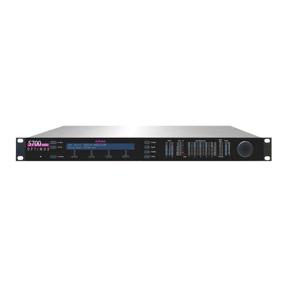
OPTIMOD-FM DIGITAL OPERATION Section 3 Operation 5700i Front Panel • Screen Display labels the four soft buttons and provides control-setting infor- mation. • Screen Contrast button adjusts the optimum viewing angle of the screen dis- play. • Four Soft buttons provide access to all 5700i functions and controls. The func- tions of the soft buttons change with each screen, according to the labels at the bottom of each screen. - Page 166 OPERATION ORBAN MODEL 5700i • Input meters show the peak input level applied to the 5700i’s analog or digital inputs with reference to 0 = digital full-scale. If the input meter’s red segment lights up, you are overdriving the 5700i’s analog to digital converter, which is a very common cause of audible distortion.
-
Page 167: Introduction To Processing
OPTIMOD-FM DIGITAL OPERATION switch the meter so that it reads the gain reduction of the Master (above-200 Hz) band, the Bass (below-200Hz) band, or the difference between the gain re- ductions in the Master and Bass bands. The latter reading is useful for assessing the dynamic bass equalization that the AGC produces, and it helps you set the AGC BASS COUPLING control. -
Page 168: Distortion In Processing
In FM processing, there is a direct trade-off between loudness, brightness, and dis- tortion. You can improve one only at the expense of one or both of the others. Thanks to Orban’s psychoacoustically optimized designs, this is less true of Orban... -
Page 169: Optimod-Fm-From Bach To Rock
OPTIMOD-FM DIGITAL OPERATION processors than of any others. Nevertheless, all intelligent processor designers must acknowledge and work within the laws of physics as they apply to this trade-off. Perhaps the most difficult part of adjusting a processor is determining the best trade-off for a given situation. -
Page 170: Fundamental Requirements: High-Quality Source Material And Accurate Monitoring
CDs that this energy cannot possibly survive the FM pre-emphasis / de- emphasis process. Although the 5700i loses less high frequency energy than any pre- vious Orban processor (due to improvements in high frequency limiting and clipping technology), it is nevertheless no match for CDs that are mastered so bright that they will curl the vinyl off car dashboards. -
Page 171: About The 5700I's Signal Processing Features
OPTIMOD-FM DIGITAL OPERATION About the 5700i’s Signal Processing Features Dual-Mono Architecture The 5700i implements full dual-mono architecture in both the AGC and the multi- band compressor sections. You can couple each band in both the AGC and multi- band compressors to a variable extent—anywhere from perfect stereo coupling to completely uncoupled operation. - Page 172 Stereo Enhancement: The 5700i provides two different stereo enhancement algo- rithms. The first is based on Orban’s patented analog 222 Stereo Enhancer, which in- creases the energy in the stereo difference signal (L–R) whenever a transient is de- tected in the stereo sum signal (L+R).
- Page 173 622B), using a sophisticated, proprietary optimization program. The curves are matched to better than 0.15 dB. This means that their sound is very close to the sound of an Orban analog parametric. They also use very high quality filter algo- rithms to ensure low noise and distortion.
- Page 174 See To Override the Speech/Music Detector on page 3-63. DSP-derived Stereo Encoder: The 5700i’s stereo encoder is derived from algo- rithms first developed for the high-performance Orban 8218 stand-alone encoder. The 5700i’s stereo encoder operates at 512 kHz-sample rate to ease the performance requirements of the D/A converter’s reconstruction filter, making it possible to...
- Page 175 IMIT RIVE control as usual Composite Limiter/Clipper: Orban has traditionally opposed composite clipping because of its tendency to interfere with the stereo pilot tone and with subcarriers, and because it causes inharmonic aliasing distortion, particularly between the stereo main and subchannels. Protecting the pilot tone and subcarrier regions is particu- larly difficult with a conventional composite clipper because appropriate filters will not only add overshoot but also compromise stereo separation—filtering causes the...
-
Page 176: Itu-R 412 Compliance For Analog Fm Broadcasts
3-12 OPERATION ORBAN MODEL 5700i For those who prefer the sound of conventional composite clipping, we also offer a defeatable composite clipper. This also provides excellent spectral protection for the pilot tone and subcarriers. The composite clipper drives the “Half-Cosine Interpola- tion”... -
Page 177: Two-Band Purist Processing
3-13 OPTIMOD-FM DIGITAL OPERATION The 5700i gives you control over the Multiplex Power Threshold (in the Input/output Utilities screen). This allows you to compensate for overshoots in the signal path up- stream from the 5700i, preventing excessive reduction of the multiplex power. Power control is applied to all outputs, not just the composite output. -
Page 178: Bs.1770 Compliance For Digital Radio
3-14 OPERATION ORBAN MODEL 5700i Except for the fact that its input has been de-emphasized, the HD look-ahead limiter receives the same processing as the FM peak limiting section if the FM HD C ONTROL is set to FM HD. Earlier processing has often been adjusted to help com-... -
Page 179: Customizing The 5700I's Sound
3-15 OPTIMOD-FM DIGITAL OPERATION essing advances further and further from its analog roots, this is the inevitable price of progress. 18 ms is below the psychoacoustic “echo fusion threshold,” which means that talent will not hear discrete slap echoes in their headphones. This means that they can monitor comfortably off-air without being distracted or confused. -
Page 180: Advanced Modify
3-16 OPERATION ORBAN MODEL 5700i optimized by Orban’s audio processing experts on the basis of years of experience designing audio processing, and upon hundred of hours of listening tests. As you increase the setting of the L control, the air sound will become louder, but (as with any processor) processing artifacts will increase. -
Page 181: Gain Reduction Metering
3-17 OPTIMOD-FM DIGITAL OPERATION in Full or Advanced Modify, L control is no longer available in Basic Modify. As noted above, we strongly recommend using the L control to achieve a sound as close as possible to your desired sound before you make further modifications at the Full or Advanced Modify levels. -
Page 182: About The Processing Structures
3-18 OPERATION ORBAN MODEL 5700i Some non-alphanumeric characters (such as < and >) are reserved and cannot be used in preset names. D) Use the knob to set the each character in the preset name. Use the Next and Prev buttons to control the cursor position. -
Page 183: Factory Programming Presets
Unused structures operate constantly in the background, so switching between structures occurs with a seamless cross-fade. Unlike older Orban processors like the 8200, no DSP code is reloaded and no audio mute is necessary. - Page 184 3-20 OPERATION ORBAN MODEL 5700i FACTORY PROGRAMMING PRESETS CLASSICAL-5 BAND CLASSICAL-5 BAND CLASSICAL-5B+AGC CLASSICAL-5B+AGC COUNTRY-MEDIUM ROCK-SMOOTH COUNTRY-LIGHT ROCK-LIGHT COUNTRY UL COUNTRY UL CRISP CRISP DANCE ENERGY DANCE ENERGY EDGE EDGE 10.0 FOLK-TRADITIONAL ROCK-SOFT GOLD GOLD GREGG GREGG GREGG OPEN GREGG OPEN...
- Page 185 Bass, Mid EQ, and HF EQ controls. Un- ASIC ODIFY like Orban’s 8200, you can make changes in EQ (and stereo enhancement) without losing the ability to use L settings. Of course, L is still available for the unedited preset if you want to go back to it.
- Page 186 3-22 OPERATION ORBAN MODEL 5700i • Presets with LL in their names use the Hard LL bass clipper mode to achieve 13 ms input-output delay. • The remaining presets have “optimum delay,” which is approximately 18 ms de- lay (5-band) and 21 ms delay (2-band).
- Page 187 GREGG: GREGG, GREGG OPEN, and GREGG LL all use a 200 Hz band1/band2 crossover frequency to achieve a bass sound similar to the classic five-band Gregg Labs FM processors designed by Orban’s Vice President of New Product Develop- ment, Greg Ogonowski. Dynamically, these presets produce a slight increase in bass energy below 100 Hz and a decrease of bass energy centered at 160 Hz.
- Page 188 3-24 OPERATION ORBAN MODEL 5700i JAZZ: JAZZ is specifically tailored toward stations that play mostly instrumental mu- sic, particularly classic jazz (Coltrane, Mingus, Monk, etc.). It is a quiet preset with a very clean, mellow high end to prevent stridency on saxes and other horns. It pre- serves much of the qualities of the original recordings, doing light re-equalization.
- Page 189 3-25 OPTIMOD-FM DIGITAL OPERATION LOUD-PUNCHY is the quietest of the “loud” preset family. It is designed for a bright, sizzling top end and very punchy lows. It is a good choice for stations that feel that the LOUD-HOT presets are too aggressive, but that think that the ROCK presets are insufficiently loud for their market position.
-
Page 190: Equalizer Controls
3-26 OPERATION ORBAN MODEL 5700i ROCK-SMOOTH has the same mellow, easy-to-listen-to high frequency quality as ROCK-SOFT, but with more density. Again, it is a good choice for female-skewing formats, but where you need more compression and density than you get with ROCK-SOFT. - Page 191 So be aware the large fixed bass boosts may have a different effect than you expect because of the way that they interact with the multiband compressor. Low Frequency Parametric Equalizer is a specially designed parametric equalizer whose boost and cut curves closely emulate those of a classic Orban analog para-...
- Page 192 3-28 OPERATION ORBAN MODEL 5700i metric equalizer with conventional bell-shaped curves (within ±0.15 dB worst-case). This provides warm, smooth, “analog-sounding” equalization. LF FREQ determines the center frequency of the equalization, in Hertz. Range is 20-500Hz. LF GAIN determines the amount of peak boost or cut (in dB) over a ±10 dB range.
- Page 193 100Hz in combination with a Bass Shelf boost at 6 dB/octave. The equalizer, like the classic Orban analog parametrics such as the 622B, has con- stant “Q” curves. This means that the cut curves are narrower than the boost curves.
- Page 194 The difference will never exceed the difference that would have otherwise occurred if the lowest frequency band was independently gated. If you are familiar with older Orban processors like the 8200, this is the maximum amount of boost that would have occurred if you had set their...
-
Page 195: Stereo Enhancer Controls
The stereo enhancer is common to the FM and HD processing chains. You can oper- ate it in one of two modes or “styles.” The first emulates the Orban 222 analog ste- reo enhancer, while the second mode, called Delay, emulates a popular enhancer from another manufacturer that adds a delayed version of the L–R signal to the... -
Page 196: Agc Controls
3-32 OPERATION ORBAN MODEL 5700i Stereo Enhancer Controls PC Remote Name Range Amount 0.0 ... 10.0 In / Out Out / In Ratio Lim 70 … 100% Diffusion Off, 0.3 ... 10.0 Style 222 / Delay Depth 0 … 10 Table 3-3: Stereo Enhancer Controls •... - Page 197 (such as a CLASSICAL preset). The AGC is also ordinarily de- feated if you are using an external AGC (like Orban’s 6300). However, in this case it is better to defeat the AGC globally in the System Setup screen.
- Page 198 3-34 OPERATION ORBAN MODEL 5700i gated. (It gates whenever the input level to the structure is below the threshold of gating.) The total amount of gain reduction in the Five-Band structure is the sum of the gain reduction in the AGC and the gain reduction in the multiband compressor. The total system gain reduction determines how much the loudness of quiet passages will be increased (and, therefore, how consistent overall loudness will be).
- Page 199 3-35 OPTIMOD-FM DIGITAL OPERATION those bands when the gate first turns on. This prevents obvious midrange coloration under gated conditions, because bands 2 and 3 have the same gain. The gate also independently freezes the gain of the two highest frequency bands (forcing the gain of the highest frequency band to be identical to its lower neigh- bor) and independently sets the gain of the lowest frequency band according to the setting of the DJ B...
- Page 200 Previous Orban AGCs had compression ratios very close to ∞:1, which produces the most consistent and uniform sound. However, the 5700i compressor can reduce this ratio to as low as 2:1.
- Page 201 3-37 OPTIMOD-FM DIGITAL OPERATION control at its factory setting unless you have a good reason HRESH for readjusting it. Idle Gain. The “idle gain” is the target gain of the AGC when the silence gate is ac- tive. Whenever the silence gate turns on, the gain of the AGC slowly moves towards the idle gain.
-
Page 202: Peak Limiter Controls
3-38 OPERATION ORBAN MODEL 5700i cause the Five-Band structure uses phase-rotating crossovers in the five- band compressor / limiter, there is little or nothing to be gained by using a phase-linear crossover in the Five-Band structure’s AGC. (Linear-Phase; no delay) is a phase-linear crossover whose upper band is de- rived by subtracting its lower band from the crossover’s input. - Page 203 3-39 OPTIMOD-FM DIGITAL OPERATION allows bass transients (like kick drums) to make square waves. The peak level of the fundamental component of a square wave is 2.1 dB higher than the peak level of the flat top in the square wave. Therefore, this al- lows you to get low bass that is actually higher than 100% modulation—...
- Page 204 3-40 OPERATION ORBAN MODEL 5700i • uses the most sophisticated look-ahead signal processing to reduce distor- tion further. Using S adds an additional 18 ms of delay to the processing (so that the total is approximately 36 ms). are not available in Low Latency mode. The bass clipping is always...
- Page 205 The final clipper operates at 256 kHz sample rate and is fully anti-aliased. Composite Limit Mode determines if the composite limiter will operate as a hard clipper or as Orban’s patented “Half-Cosine Interpolation” composite limiter (which is not a clipper).
- Page 206 3-42 OPERATION ORBAN MODEL 5700i When operating as a hard clipper, the composite limiter will produce maximum brightness in the frequency range from 5 to 15 kHz because, unlike the 5700i’s left/right audio-domain peak limiters, it can produce square waves in this frequency range. The downside compared to Half- Cosine mode is that it can noticeably compromise stereo imaging.
- Page 207 3-43 OPTIMOD-FM DIGITAL OPERATION control is accessible only from the 5700i VERSHOOT OMPENSATOR RIVE PC Remote software.) Pilot Protect (Pilot Protection Filter) turns the 19 kHz notch filter on or off. It af- fects the composite output only. The 5700i’s composite limiter always protects frequencies above 53 kHz. However, the 19 kHz notch filter can introduce substantial overshoot with certain program material when the composite limiter is driven hard.
-
Page 208: The Two-Band Structure
Five-Band structure. Like the “Two-Band Purist” structure in Orban’s OPTIMOD-FM 8200, the 5700i’s Two-Band Structure is phase-linear through- out to maximize sonic transparency. -
Page 209: The Protection Presets
3-45 OPTIMOD-FM DIGITAL OPERATION ance between the bass and high frequency energy of the program material is incor- rect, the Two-Band structure (when its BAND COUPLING 2>1 control is operated to- ward 0%) can gently correct it without introducing obvious coloration. The Two-Band structure is mainly useful for classical or “fine arts”... -
Page 210: Customizing The Settings
3-46 OPERATION ORBAN MODEL 5700i poses, inaudible to the listener. Low-level passages are increased in level by up to 10 dB, while the dynamics of crescendos are maintained. The CLASSICAL-2 BAND preset is a two-band preset with the AGC turned off. It uses considerable bass coupling to preserve the spectral balance of the input as well as possible. -
Page 211: The Two-Band Structure's Setup Controls
3-47 OPTIMOD-FM DIGITAL OPERATION The Two-Band Structure’s Setup Controls The tables below show a summary of the Two-Band controls in the dynamics section. These controls are available only from PC Remote. AGC, Equalizer, Stereo Enhancer, and Clipper controls are common to both Two-Band and Five-Band structures and are described in their own sections earlier in Section 3. - Page 212 3-48 OPERATION ORBAN MODEL 5700i ed by the silence gate. The release time can be adjusted from 0.5 dB / second (slow) to 20 dB / second (fast). Settings toward 20 dB / second result in a more consistently loud output, while set- tings toward 0.5 dB / second allow a wider variation of dynamic range.
- Page 213 3-49 OPTIMOD-FM DIGITAL OPERATION The two-band gain reduction will eventually recover to 0 dB and the AGC gain re- duction will eventually recover to –10 dB even when their compressor gates are gat- ed. However, recovery is slow enough to be imperceptible. This avoids OPTIMOD- FM’s getting stuck with a large amount of gain reduction on a long, low-level musi- cal passage immediately following a loud passage.
- Page 214 3-50 OPERATION ORBAN MODEL 5700i 2B Bass Comp Threshold determines the compression threshold of the bass band in the Two-Band Compressor. It can be used to set the target spectral balance of the Two-Band Compressor. As the Two-Band Compressor B...
-
Page 215: The Five-Band Structure
3-51 OPTIMOD-FM DIGITAL OPERATION The HF Limiting control is in the clippers screen in the unit. HF Clip Threshold sets the threshold of the multiband, distortion-cancelled clipper in the Two-Band structure’s high frequency limiter. Higher numbers yield more brightness, but also cause more high frequency distortion. This control does not affect the HD processing chain. -
Page 216: Customizing The Settings
3-52 OPERATION ORBAN MODEL 5700i Customizing the Settings The L control can edit each of these presets to optimize the trade-off be- tween loudness and distortion according to the needs of the format. The presets can be further edited with Basic, Full Modify, or Advanced Modify to fine-tune them. - Page 217 3-53 OPTIMOD-FM DIGITAL OPERATION these faster release times produce more limiting action. Increasing density can make sounds seem louder, but can also result in an unattractive busier, flatter, or denser sound. It is very important to be aware of the many negative subjective side effects of excessive density when setting controls that affect the density of the processed sound.
- Page 218 3-54 OPERATION ORBAN MODEL 5700i You can minimize this effect by carefully setting the MB G HRESH control to “freeze” the gain when the input gets quiet and/or by activat- ing the single-ended noise reduction. When the multiband compressor’s release time is set to its faster settings, the setting...
- Page 219 3-55 OPTIMOD-FM DIGITAL OPERATION music is noticeably altered to a standard. Bass has an ever-present punch, there is always a sense of presence, and highs are in perfect balance to the mids, no mat- ter what was on the original recording. •...
- Page 220 3-56 OPERATION ORBAN MODEL 5700i can go without causing unacceptable listener fatigue. However, this sound may be useful for stations that are ordinarily heard very softly in the background be- cause it improves intelligibility under these quiet listening conditions. Stations...
- Page 221 3-57 OPTIMOD-FM DIGITAL OPERATION MB Clipping sets the drive level to the multiband distortion controlling processing that precedes the final clipping section. The distortion-controlling section uses a combination of distortion-cancelled clipping and look-ahead processing to antici- pate and prevent excessive clipping distortion in the final clipper. Like any other dynamics processing, the distortion-controlling section can produce artifacts of its own when overdriven.
- Page 222 3-58 OPERATION ORBAN MODEL 5700i Note also that it is virtually impossible to achieve undetectable dynamic noise reduc- tion of program material that is extremely noisy to begin with, because the program never masks the noise. It is probably wiser to defeat the dynamic noise reduction with this sort of material (traffic reports from helicopters and the like) to avoid ob- jectionable side effects.
- Page 223 3-59 OPTIMOD-FM DIGITAL OPERATION There are two sets of mixer controls, one for the analog processing chain and one for the HD processing chain. The mixer controls for the HD processing chain also de- termine the spectral balance of the low-delay monitor output. The range of the band mix controls has been purposely limited because the only gain control element after these controls is the back-end clip- ping system (including the multiband clipper / distortion controller),...
- Page 224 3-60 OPERATION ORBAN MODEL 5700i dependently. This is a feature designed for intermediate or advanced users and de- velopers when they are creating new 5700i presets. The mute control for a given band affects both the FM and HD processing because it mutes the input of compres- sor in that band.
- Page 225 3-61 OPTIMOD-FM DIGITAL OPERATION loudness and brightness. For these presets, we found it necessary to set the MB L control substantially higher than “0” to permit more IMIT clipping depth. In some cases, this results in substantially objectionable distortion artifacts with isolated program material. However, this is the price to be paid for this extreme level of on-air loudness.
- Page 226 3-62 OPERATION ORBAN MODEL 5700i MB DownExpStCpl (“Multiband Downward Expander Stereo Coupling”) deter- mines whether the multiband downward expander stereo coupler is on or off. B1 / B2 Xover (Band 1 to Band 2 Crossover Frequency) sets the crossover frequency between bands 1 and 2 to either 100 Hz, 150 Hz, or 200 Hz.
-
Page 227: To Override The Speech/Music Detector
3-63 OPTIMOD-FM DIGITAL OPERATION Speech is detected if (1) the input is mono, and (2) there are syllabic pauses at least once every 1.5 seconds. Speech with a stereo music back- ground will usually be detected as “music,” or the detector may switch back and forth randomly if the stereo content is right at the stereo / mono detector’s threshold. -
Page 228: About The 5700I's Hd / Digital Radio Processing
Model 5700iFM can be upgraded to an 5700iHD in the field via the 5700iUPG/HD upgrade kit, which can be purchased from your Orban dealer. Units are upgraded from a PC; it is unnecessary to remove the 5700i from the rack. - Page 229 3-65 OPTIMOD-FM DIGITAL OPERATION • Set the band 5 compression threshold to match the codec that the 5700i’s HD output is driving. Adjust the threshold until you find a good compromise be- tween presence and high frequency codec artifacts. We find the range from –6.0 to +6.0 dB to be useful.
-
Page 230: Delay Difference Between Hd And Fm Outputs
3-66 OPERATION ORBAN MODEL 5700i Delay Difference between HD and FM Outputs In order to make the receiver analog/digital crossfade free from comb filtering, the time delays in the HD Radio’s FM and HD channels must have a fixed and predictable offset, correctly implementing the HD Radio receiver’s “time diversity”... - Page 231 3-67 OPTIMOD-FM DIGITAL OPERATION digital-channel look-ahead limiter (E NABLED The HD look-ahead limiter is not stereo-coupled. This prevents limiting on one channel from causing audible modulation effects on the other channel. HD HF Shelf EQ (Pre/Post) determines whether the HD HF shelving equalizer will be placed before or after the look-ahead limiter that feeds the HD output.
-
Page 232: Digital Output
3-68 OPERATION ORBAN MODEL 5700i The user should carefully test the codec in use to ascertain if lowering the bandwidth to 15 kHz improves subjective quality. This can occur because the codec then uses all of its bits to encode information in the most sub- jectively important part of the ear’s bandwidth. - Page 233 3-69 OPTIMOD-FM DIGITAL OPERATION justment allows you to ensure compatibility with downstream equipment requiring a fixed sample rate. A 32 kHz sample rate cannot represent frequencies higher than approxi- mately 15 kHz. Therefore, setting the sample rate to 32 kHz automati- cally forces the bandwidth to 15 kHz, regardless of the setting of the HD control.
-
Page 234: Unique Hd Audio Controls
3-70 OPERATION ORBAN MODEL 5700i Format determines if the digital-channel output follows the professional AES3 or consumer SPDIF standard. We expect that AES will be appropriate for almost all users, but some consumer sound cards may require SPDIF. BS.1770 Safety Limiter ON/OFF activates or defeats the BS.1770 Safety Limiter, which is applied only to the digital radio processing. - Page 235 3-71 OPTIMOD-FM DIGITAL OPERATION HD EQ Gain determines the depth of high frequency shelving equalization pro- duced by the parametric HF shelving equalizer, which will be placed either before or after the digital-channel look-ahead limiter (depending on the setting of the HD HF EQ control in the I screen).
-
Page 236: Itu-R Multiplex Power Controller
3-72 OPERATION ORBAN MODEL 5700i channel to the loudness of the FM channel at the receiver. In an HD Radio receiver, the HD channel has 5 dB higher gain than the ana- log FM channel. Because the digital channel’s loudness must match the FM channel during receiver crossfades, there is no need to over-process the HD channel;... -
Page 237: Mpx Power Meter
3-73 OPTIMOD-FM DIGITAL OPERATION MPX Power Meter Version 1.1 of 5700i software added a MPX P meter that indicates MPX power OWER according to the ITU-R BS.412 standard. All samples are weighted equally in a 60- second sliding window. BS.412 requires limiting the integrated power of the composite signal so that it does not exceed the power in a sinewave that deviates the FM carrier by ±19 kHz (25.333% modulation with reference to ±75 kHz deviation). - Page 238 3-74 OPERATION ORBAN MODEL 5700i 9 control (see step 1 on page 2-23). Set it OFF if your country does not enforce the standard. The control is located in the Setup > S screen because the regulation TEREO NCODER applies to all operation of the processor in a given installation.
-
Page 239: Audio Processing And The Multiplex Power Threshold Control
3-75 OPTIMOD-FM DIGITAL OPERATION transmission system following the 5700i. For example, if RF peak deviation exceeds the peak deviation produced by the 5700i’s sinewave oscillator (set for 100% modu- lation) by 3 dB, set the MULTIPLEX POWER THRESHOLD to “+3.” Audio Processing and the Multiplex Power Threshold Control Starting with version1.1 software, the multiplex power controller reduces multiplex power by applying gain reduction after the Optimod’s FM peak limiting system,... - Page 240 TRLR control is part of the active processing preset. • Preset 0: No gating: Works like Orban’s older, non-gated MPX power controller. • Preset 1: Only the quieter passages are gated and the gated release is faster than it is in the other presets. Created to maximize loudness within the BS.412 limit while providing more on-air dynamics and preventing unnecessary gain pump-ups.
-
Page 241: Test Modes
3-77 OPTIMOD-FM DIGITAL OPERATION Test Modes Setup: Test Parameter Units Default Range (CCW to CW) Step Labels MODE Operate Operate, Bypass, Tone −18 … +25 BYPASS GAIN TONE FREQ 16, 20, 25, 31.5, 40, 50, 100, 125, 160, 200, 250, 315, 400, 500, 630, 800, 1000, 1250, 1600, 2000, 2500, 3150, 4000, 5000, 6300, 8000, 9500, 10000,... -
Page 242: Getting The Bass Sound You Want
ORBAN MODEL 5700i While this calibration may seem unintuitive, experience has shown that it greatly reduces calls to Orban customer service complaining that the frequency response of the transmission path is not flat when in fact the measurement in question was causing undetected clipping at high frequencies due to preemphasis. - Page 243 3-79 OPTIMOD-FM DIGITAL OPERATION settings in the factory presets have been adjusted with this tradeoff in TTACK mind, but you might prefer to make a different one. The threshold of the band 1 compressor will also affect bass punch. We recommend that you carefully study the setting of this control (and the B con- TTACK...
-
Page 244: Summary
Before running 5700i PC Remote, you must have installed the appropriate Windows communications services on your computer. By default, the installer installs a short- cut to 5700iPC.exe on your desktop and in your Start Menu under Orban\Optimod 5700i. 5700i PC Remote can control only one 5700i at a time, but it can readily switch be- tween several 5700i. -
Page 245: To Set Up A New Connection
3-81 OPTIMOD-FM DIGITAL OPERATION Before your PC can communicate with a given 5700i, you must first set up a “con- nection,” which is information that allows PC Remote to locate and communicate with the 5700i. To set up a new connection: A) Launch 5700iPC.exe. -
Page 246: To Modify A Control Setting
“Loading system files, please wait.” When run, the Orban PC Remote software installer makes copies of all 5700i fac- tory preset files on your local hard drive. The PC Remote software reads these files to speed up its initialization. -
Page 247: To Save A User Preset You Have Created
The encryption options prevent archived presets, system files, and auto- mation files from being restored if the user does not have the password used for the encryption. There is no “back door”— Orban cannot help you to decrypt a preset whose password is unknown. -
Page 248: To Restore Archived Presets, System Files, And Automation Files
All User Presets are compatible with all 5700i software versions and are compatible with both 5700iHD and 5700iFM. If Orban adds new controls to a software version, the new software will assign a reasonable default value to any control missing in an old User Preset. -
Page 249: To Modify Input /Output And System Setup
3-85 OPTIMOD-FM DIGITAL OPERATION You can elect to restore all user presets (*.orb57user, *.orb), 8600 user presets (*.orb86suser), 5500 user presets (*.orb55user), 8400 user presets (*.orbu), 8500 user presets (*.orb85user), 8600 user presets (*.orb86user) , 8600S user presets (*.orb86suser), system files (*.orb57setup), and auto- mation files (*.orb57autom). -
Page 250: To Modify Automation
3-86 OPERATION ORBAN MODEL 5700i To set a control, click it (it will become highlighted) and then use the wheel on the mouse to adjust it. You can also use the + and – keys on the numeric keypad to adjust any control. -
Page 251: About Aliases Created By Optimod 5700I Pc Remote Software
Optimod 5700i PC Re- mote (usually \Program Files\Orban\Optimod 5700i). The folder has the same name as the Alias name. Once you establish the initial connection to the 5700i, all presets for that 5700i are automatically copied to the Alias folder;... - Page 252 To prevent the installer from overwriting the old version, you must specify a different installation folder when you install the new version (for example, \Program Files\Orban\Optimod 5700iv2). Each version of 5700i PC Remote will display all 5700i Aliases, even those pointing to 5700i with incompatible version numbers.
-
Page 253: Section 4 Maintenance
OPTIMOD-FM DIGITAL MAINTENANCE Section 4 Maintenance Routine Maintenance The 5700i OPTIMOD-FM Audio Processor uses highly stable analog and digital cir- cuitry throughout. Recommended routine maintenance is minimal. 1. Periodically check audio level and gain reduction meter readings. Become familiar with normal audio level meter readings, and with the normal performance of the G/R metering. -
Page 254: Subassembly Removal And Replacement
MAINTENANCE ORBAN MODEL 5700i Subassembly Removal and Replacement See page 6-27 for the Circuit Board Locator and Basic Interconnections diagram. 1. Removing the Top Cover: To access any internal board (including the display assembly), you must remove the top cover. - Page 255 OPTIMOD-FM DIGITAL MAINTENANCE B) Using a deep hex nut driver (preferred), a small crescent wrench, or a pair of slip-joint pliers (in an emergency), remove the nuts and lockwashers holding the four BNC connectors to the chassis. The Composite/SCA daughterboard can now be removed. 4.
- Page 256 EMI that violates FCC and/or CE regulations. If the power supply fails, please contact Orban Customer Service (custserv@orban.com) to obtain an exact replacement.
- Page 257 OPTIMOD-FM DIGITAL MAINTENANCE 9. Replacing the Composite/SCA Daughterboard Referring to step 3, follow the instructions in reverse. 10. Replacing the Front Panel Assembly: A) Set the front panel, face down, on a soft cloth to prevent scratches. B) Lightly reattach the bottom and top circuit boards by mating the four plugs and jacks.
-
Page 258: Field Audit Of Performance
MAINTENANCE ORBAN MODEL 5700i Field Audit of Performance Required Equipment: • Ultra-low distortion sine-wave oscillator/THD analyzer/audio voltmeter With verified residual distortion below 0.01%. Audio Precision System One, or similar high-performance system. The NAB Broadcast and Audio System Test CD is an excellent source of test signals when used with a high-quality CD player. - Page 259 The power supply is a module. In case of any power supply failure, the entire supply must be replaced by an exact replacement (available from Orban Service). Attempts to repair the supply on a component level and/or to replace the supply with a non-approved supply may compromise your Optimod’s compliance with...
- Page 260 MAINTENANCE ORBAN MODEL 5700i b) Navigate to Setup > I/O C . Set controls as in the table > D ALIB ALIB below: DI REF VU ................–15.0 dBFS R CH BAL ..................0.0 dB c) Navigate to Setup > I/O C .
- Page 261 OPTIMOD-FM DIGITAL MAINTENANCE C) Connect the audio voltmeter to the Left Analog Output. D) Adjust output trim VR301 to make the meter read +10.0 dBu. (0 dBu = 0.775V rms.) Verify a frequency reading of 400 Hz. E) Verify THD+N reading of <0.03% (<0.01% typical) using a 22 kHz low pass fil- ter in the distortion analyzer.
- Page 262 4-10 MAINTENANCE ORBAN MODEL 5700i H) Repeat steps (C) through (G) for the right channel. 5. Check distortion performance of Analog I/O. A) Verify 5700i software controls are set to their default settings. (Refer to page 4-7.) B) Be sure you are still in B mode [see step (3.F)] and set the B...
- Page 263 4-11 OPTIMOD-FM DIGITAL MAINTENANCE D) Set the I to D NPUT IGITAL E) Connect the digital source generator to the AES3 Digital Input XLR connector of the 5700i. F) Set the frequency of the digital source generator to 400 Hz and its output lev- el to 18 dB below full scale.
- Page 264 4-12 MAINTENANCE ORBAN MODEL 5700i An analog oscilloscope can be used for a more thorough test. Set the scope for X/Y operation (i.e., so that it generates Lissajous patterns). Connect the reference generator to one input and the 5700i’s digital output to the other input.
- Page 265 4-13 OPTIMOD-FM DIGITAL MAINTENANCE You will have to press the N button to access all of these parameters. E) Navigate to Setup > S TEREO NCODER F) Set the C control to make the stereo monitor read 100% total modu- lation.
- Page 266 4-14 MAINTENANCE ORBAN MODEL 5700i tion executes when you activate the input. To program a GPI input, see Remote Control Interface Programming on page 2-43. B) You can test the RS-232 port for functionality by verifying that you can con- nect to a PC through a null modem cable.
-
Page 267: Section 5 Troubleshooting
OPTIMOD-FM DIGITAL TROUBLESHOOTING Section 5 Troubleshooting Problems and Potential Solutions Always verify that the problem is not the source material being fed to the 5700i, or in other parts of the system. RFI, Hum, Clicks, or Buzzes A grounding problem is likely. Review the information on grounding on page 2-11. The 5700i has been designed with very substantial RFI suppression on its analog and digital input and output ports, and on the AC line input. -
Page 268: Unexpected Delay Between The Program Feed And The On-Air Signal
Many commercial monitors have this problem, but most of these problem units can be modified to indicate peak levels accurately. Orban uses the Belar “Wizard” series of DSP-based monitors internally for testing, because these units do not have this difficulty. -
Page 269: Audible Noise On Air
STL may only be 70-75 dB. In this case, it is wise to use the Orban 8200ST Studio AGC to perform the AGC func- tion prior to the STL transmitter and to control the STL's peak modulation. This will optimize the signal-to-noise ratio of the entire transmission system. -
Page 270: Whistle On Air, Perhaps Only In Stereo Reception
TROUBLESHOOTING ORBAN MODEL Whistle on Air, Perhaps Only in Stereo Reception The most likely cause is oscillation in the analog input or output circuitry. If the oscil- lation is in the output circuitry and is between 23 and 53 kHz, it will be detected in a receiver’s stereo decoder and translated down into the audible range. -
Page 271: Shrill, Harsh Sound
OPTIMOD-FM DIGITAL TROUBLESHOOTING Amplitude modulation of the carrier that is synchronous with the program (“syn- chronous AM”) can cause program-related crosstalk into subcarriers. Synchronous AM should be better than 35 dB below 100% modulation as measured on a syn- chronous AM detector with standard FM de-emphasis (50μs or 75μs). The subcarrier receiver itself must receive a multipath-free signal, and must have a wide and symmetrical IF passband and a linear, low-distortion FM demodulator to prevent program-related crosstalk into subcarriers. -
Page 272: System Will Not Pass Emergency Alert System ("Eas" Usa Standard) Tones At The Legally Required Modulation Level
First, verify that a problem really exists by using a second frequency-measuring de- vice and/or verifying the problem with a monitoring service. If the problem is real, contact Orban Customer Service for a crystal replacement; there is no frequency trim available. -
Page 273: Harsh Sibilance ("Ess" Sounds) In The Hd Channel
OPTIMOD-FM DIGITAL TROUBLESHOOTING Harsh Sibilance (“Ess” Sounds) in the HD Channel Adjust the HD D control and/or activate the HD channel’s band 5 compressor. See page 3-72. HD and FM Levels Do Not Match When the Receiver Crossfades Adjust the HD L control in the on-air preset to match levels. - Page 274 TROUBLESHOOTING ORBAN MODEL pression), overshoot in the transmission link (including the FM exciter) following the 5700i, or an inaccurate modulation monitor that is causing you to under-modulate the carrier. A station may suffer from any combination of these problems, and they can have a remarkable effect on the overall competitiveness of a station’s sound.
-
Page 275: You Cannot Access The Internet After Making A Direct Or Modem Connection To The 5700I
OPTIMOD-FM DIGITAL TROUBLESHOOTING If you are connecting via Direct Serial Connection or modem, review the Proper- ties you have set on that connection. Double-check to ensure that you have set Windows parameters as described in Appendix: Setting Up Serial Communica- tions on page 2- 61. -
Page 276: Os-Specific Troubleshooting Advice
5-10 TROUBLESHOOTING ORBAN MODEL OS-Specific Troubleshooting Advice Troubleshooting Windows 2000 Direct Connect: If you are having trouble establishing a connection, check your New Connection’s properties to make sure they are set up correctly: A) Click “Start > Programs > Accessories > Communications > Network and Dia- lup Connections”... -
Page 277: Troubleshooting Windows 2000 Modem Connect
5-11 OPTIMOD-FM DIGITAL TROUBLESHOOTING you already set this speed when you configured your PC ports, you shouldn’t have this problem. The 5700i communicates at 115200 bps. COM ports on some older PCs are incapable of communications at this rate and may not work reliably. Most newer PCs use 16550-compatible UARTS, which support the 115200 bps rate. -
Page 278: Troubleshooting Windows Xp Direct Connect
5-12 TROUBLESHOOTING ORBAN MODEL J) Set “Type of dial-up server I am calling” to “PPP: Windows 95/98/NT4/2000, In- ternet.” K) Select the “Settings” button and make sure all PPP settings are unchecked. Then click “OK.” L) In “Components checked are used by this connection,” uncheck all except for “Internet Protocol (TCP/IP).”... -
Page 279: Troubleshooting Windows Xp Modem Connect
5-13 OPTIMOD-FM DIGITAL TROUBLESHOOTING H) In “This connection uses the following items,” select “Internet Protocol (TCP/IP)” and then click the “Properties” button. The “Internet Protocol (TCP/IP) Properties” window opens. I) Choose “Obtain an IP address automatically” and “Obtain DNS server address automatically”... -
Page 280: Troubleshooting Ic Opamps
Know the serial number of your 5700i ⎯ this is printed on the rear panel of the unit. Please check Orban’s website, www.orban.com, for Frequently Asked Questions and other technical tips about 5700i that we may post from time to time. Manuals (in .pdf form) and 5700i software upgrades will be posted there too —... -
Page 281: Factory Service
Returned units will be returned C.O.D. if the unit is not under warranty. Orban will pay return shipping if the unit is still under warranty. In all cases, the customer pays transportation charges to the factory (which are usually quite nominal). -
Page 283: Section 6 Technical Data
OPTIMOD-FM DIGITAL TECHNICAL DATA Section 6 Technical Data Specifications It is impossible to characterize the listening quality of even the simplest limiter or compressor based on specifications, because such specifications cannot adequately describe the crucial dynamic processes that occur under program conditions. There- fore, the only way to evaluate the sound of an audio processor meaningfully is by subjective listening tests. -
Page 284: Installation
TECHNICAL DATA ORBAN MODEL 5700i Processing Resolution: Internal processing has 24 bit (fixed point) or higher resolution. Installation Delay Defeatable Analog FM Processing delay: 0.27 to 16.384 seconds, adjustable in one- sample increments at 64 kHz sample rate to allow the delays of the analog and digital paths in the HD Radio system to be matched at the receiver output. - Page 285 OPTIMOD-FM DIGITAL TECHNICAL DATA Digital Audio Input Configuration: Stereo per AES3 standard, 24 bit resolution, software selection of stereo, mono from left, mono from right or mono from sum. Sampling Rate: 32, 44.1, 48, 88.2, or 96 kHz, automatically selected. Can be used as a sync reference.
- Page 286 TECHNICAL DATA ORBAN MODEL 5700i AES3id Input Configuration: Can receive the output of a ratings encoder. See Connecting a Ratings En- coder on page 2-8. Connector: BNC female, grounded to chassis, terminated with 75Ω. For short cable runs, there is usually no problem in driving this with an AES3 (110Ω) signal. If the cable is long enough to cause digital audio reception errors due to impedance mismatch, a 110Ω/75Ω...
- Page 287 OPTIMOD-FM DIGITAL TECHNICAL DATA Connectors: Two BNC, shell connected to chassis ground, EMI suppressed. 19 kHz Pilot Reference: SCA2 input can be re-jumpered to provide a 19 kHz pilot reference output. Remote Computer Interface Supported Computer and Operating System: IBM-compatible PC running Microsoft Win- dows®...
-
Page 288: Circuit Description
RFI/EMI: Tested according to Cenelec procedures. FCC Part 15 Class A device. Shipping Weight: 10 lbs / 4.6 kg Warranty Two Years, Parts and Service: Subject to the limitations set forth in Orban's Standard Warranty Agreement. Because engineering improvements are ongoing, specifications are subject to change with- out notice. -
Page 289: Control Circuits
DSP code download has finished. If you hear a brief audio mute on air and you know that its input was not interrupted, you can assume that the 5700i has rebooted for some reason. Be prepared to convey this fact to Orban cus- tomer service if you call for technical assistance. - Page 290 TECHNICAL DATA ORBAN MODEL 5700i Remote Interface and RS-232 Interfaces Located on control board A remote interface connector and circuitry implements remote control of certain operating modes; Model 5700i OPTIMOD-FM has eight remote contact closure inputs. A valid remote signal is a momentary pulse of current flowing through remote signal pins.
-
Page 291: Input Circuits
OPTIMOD-FM DIGITAL TECHNICAL DATA essor, which sends the appropriate LED control words (eight bits at a time) to the data latches that drive the LEDs directly. Component-Level Description: The meter LED matrix consists of ten 10-segment LED bar graph assemblies (CR1-CR9, CR16) and one discrete LED (CR10). - Page 292 6-10 TECHNICAL DATA ORBAN MODEL 5700i and scales the signal to the proper level for the analog-to-digital (A/D) con- verter IC208. IC207A and associated components comprise a servo amp to cor- rectly DC-bias the signal feeding the A/D converter. R253, R255-R257, C217, C219 make an attenuator / RC filter necessary to filter high frequency energy that would otherwise cause aliasing distortion in the A/D converter.
-
Page 293: Output Circuits
6-11 OPTIMOD-FM DIGITAL TECHNICAL DATA tor that locks to the 27 MHz output of IC1101 and generates four clock signals from it. The four outputs of IC1102 are applied to the CPLD, which closes the phase-locked loop as directed by the PIC and main microprocessor. The CPLD generates the clocks (FCLK and BCLK) used by the DSP. - Page 294 6-12 TECHNICAL DATA ORBAN MODEL 5700i a floating transformer; its differential output level is independent of whether one side of its output is floating or grounded. IC301 and its right channel counterpart IC302 are socketed in through-hole packages to facilitate field re- placement with simple tools.
-
Page 295: Dsp Circuit
During system initialization, the SC520 queries the DSP hardware about its opera- tional status and will display an error message on-screen if the DSP fails to initialize normally. Please note any such messages and be ready to report them to Orban Cus- tomer Service. -
Page 296: Abbreviations
Because of safety and EMI suppression requirements in the power supply, there are no user-serviceable parts in it. In case of failure, replace the entire supply with an Orban-supplied replacement (Orban part number 29270.000.01), which ensures that your Optimod will continue to meet all regulatory requirements for safety and emis- sions. - Page 297 6-15 OPTIMOD-FM DIGITAL TECHNICAL DATA Federal Communications Commission (USA regulatory agency) FDNR frequency-dependent negative resistor⎯an element used in RC-active filters field effect transistor fast Fourier transform FIFO first-in, first-out gain reduction HD Radio See IBOC high-frequency high-pass IBOC “In-Band On-Channel” — a form of digital radio commercialized by iBiquity Corporation where the digital carriers use a form of COFDM modulation and share the frequency alloca- tion of the analog carriers.
-
Page 298: Parts List
Consult the factory if the listing of a part includes the note “selected” or “realignment required.” Orban normally maintains an inventory of tested, exact replacement parts that can be supplied quickly at nominal cost. Standardized spare parts kits are also available. - Page 299 6-17 OPTIMOD-FM DIGITAL TECHNICAL DATA Control Board PART # DESCRIPTION COMPONENT, IDENTIFIER 24983.000.01 IC 7064STC100-10 27147.124.01 IC SOCKET DIP 24 PIN DUAL SU12 24331.033.01 IC VOLTAGE REGULATOR LT1963-3.3 SOT223 20233.472.01 RESISTOR NETWORK 4.7K CTS745C RN1, RN2, RN3, RN4 8R BUSS 21136.010.01 CAPACITOR SMT 1206 10PF 5 24331.025.01...
-
Page 300: Combined Input/Output And Dsp (I/O+Dsp) Board
6-18 TECHNICAL DATA ORBAN MODEL 5700i Control Board PART # DESCRIPTION COMPONENT, IDENTIFIER R76, R77, R80, R82 28091.000.01 XTAL 25MHZ RXD MP35L SMD 24979.000.01 IC BAT54C-7 CR11, CR12 24900.000.01 IC HEX INVERTER SMT U23, U24 22209.000.01 DIODE SCHOTTKY 1A 60V SMD CR6, CR7, CR8, CR9 22101.001.01... - Page 301 6-19 OPTIMOD-FM DIGITAL TECHNICAL DATA I/O+DSP BOARD PART # DESCRIPTION COMPONENT IDENTIFIER 24516.000.01 IC ICS501MLF IC400 24681.000.01 IC PCM1798DB D/A CNVRTR IC401 24843.000.01 IC CD74HC4046AM 16-SOIC IC1104 29552.000.01 INDUCTOR POWER 1.5UH 9A SMD L1201, L1202 24348.000.01 IC REG SYNC BUCK CLK 4A IC1201, IC1202 21329.000.01 CAPACITOR TANT 47uF 6.3V 20% sm...
- Page 302 6-20 TECHNICAL DATA ORBAN MODEL 5700i I/O+DSP BOARD PART # DESCRIPTION COMPONENT IDENTIFIER TP1201, TP1202, (TP1203, 27630.001.01 JUMPER PM MOUNT TEST PT TP1204, TP1205, NO STUFF) L201, L202, L301, L302, L501, 29539.000.01 CHOKE COMM MODE 1K OHM SM L502, L503, L504, L5022 SL203, SL204, SL205, SL206, 27408.003.01...
- Page 303 6-21 OPTIMOD-FM DIGITAL TECHNICAL DATA I/O+DSP BOARD PART # DESCRIPTION COMPONENT IDENTIFIER (C211, C212, C213, C214, NO 21170.282.01 CAPACITOR 0805 .0082U 50 5% COG STUFF) L207, L208, L209, L210, (L311, 29522.000.01 INDUCTOR 1200UH 5% 1-M-10-22 L312, L313, L314, NO STUFF) 20128.000.01 RESISTOR 0 OHM 0805 R505, R506, R1007, R1109...
- Page 304 6-22 TECHNICAL DATA ORBAN MODEL 5700i I/O+DSP BOARD PART # DESCRIPTION COMPONENT IDENTIFIER C430, C601, C602, C603, C604, C605, C606, C607, C608, C609, C610, C611, C612, C613, C614, C615, C616, C617, C618, C619, C620, C621, C622, C623, C624, C625, C626, C627, C628, C629,...
-
Page 305: Composite/Sca Daughterboard
6-23 OPTIMOD-FM DIGITAL TECHNICAL DATA I/O+DSP BOARD PART # DESCRIPTION COMPONENT IDENTIFIER R321, R322, R323, R324, R325, 20130.348.01 RESISTOR 1/8W 1% 3.48K 0805 R326, R415, R416, R417, R418, R1215 20130.162.01 RESISTOR 1/8W 1% 1.62K 0805 R241, R242, R243, R244, R1212 R203, R204, R205, R206, R1003, 20130.100.01 RESISTOR 1.00K 1% 0805... -
Page 306: Display Board
6-24 TECHNICAL DATA ORBAN MODEL 5700i COMPOSITE/SCA DAUGHTERBOARD PART # DESCRIPTION COMPONENT IDENTIFIER 20129.604.01 RESISTOR 0805 604 Ω 1% 1/8W R5, R6, R7, R8, R9, R10 20130.210.01 RESISTOR 1/8W 1% 2.10K 0805 R3, R4 20130.348.01 RESISTOR 1/8W 1% 3.48K 0805 R13, R14, R15, R16 20128.075.01... - Page 307 6-25 OPTIMOD-FM DIGITAL TECHNICAL DATA Function Description Drawing Page Chassis Circuit Board Locator and Basic In- Top view 6-27 terconnections (not to scale) Control board Control microprocessor. Services Parts Locator 6-28 front panel, serial port, Ethernet, Drawing and DSP+I/O board. Contains: General Purpose bus, address de- Schematic 1 of 5...
- Page 308 6-26 TECHNICAL DATA ORBAN MODEL 5700i...
- Page 309 6-27 OPTIMOD-FM DIGITAL TECHNICAL DATA WARNING: INPUT/OUTPUT PARTS SECTION UNDER SHIELD ARE EXPOSED TO AC LINE CONTROL INPUT/OUTPUT+DSP BOARD BOARD POWER SUPPLY DSP SECTION DISPLAY ASSEMBLY...
- Page 310 6-28 TECHNICAL DATA ORBAN MODEL 5700i CONTROL BOARD PARTS LOCATOR...
- Page 311 6-29 OPTIMOD-FM DIGITAL TECHNICAL DATA C4 4 10UF +3.3 V C4 5 10.0 K 0.1 UF S Y S TE M_RE S E T- N (S HT 5) U1 6 U5 MIC8 115TU +3.3 V U1 B S C5 20 MR- n V CC C2 0...
- Page 312 6-30 TECHNICAL DATA ORBAN MODEL 5700i MD[0..3 1] MA[0..1 2] U2 A MT4 8LC1 6 U3 A MT4 8LC1 6 U1 A S C5 20 V 26 MA12 MA12 MD1 5 MA12 MD3 1 MA12 DQ1 5 DQ1 5 U2 6...
- Page 313 6-31 OPTIMOD-FM DIGITAL TECHNICAL DATA +3.3 V P CI_ AD[0..3 1] RNE T4 .7 K +3.3 V U1 C S C5 20 U1 0A DP 83816AV NG +3.3 V P CI_ AD3 1 P CI_ AD3 1 RE Q4 AD3 1 AD3 1 P CI_ AD3 0 P CI_ AD3 0...
- Page 314 6-32 TECHNICAL DATA ORBAN MODEL 5700i P WRGOOD +3.3 V (S HT2 ) +3.3 V R4 3 R4 4 R4 5 R4 6 100K 100K 100K 0 OHM R2 6 U1 D S C5 20 (NO- S TUFF) 4.7 5K...
- Page 315 6-33 OPTIMOD-FM DIGITAL TECHNICAL DATA +3.3 V U1 0B DP 83816AV NG +3.3 V +3.3 V (NO- S TUFF) +3.3 V U2 B MT4 8LC1 6 U3 B MT4 8LC1 6 U4 B E 28F1 28 C2 01 RE S E RV E D 1.0 UF RE S E RV E D V S S...
- Page 316 6-34 TECHNICAL DATA ORBAN MODEL 5700i 5700/8600S I/O-DSP BOARD PARTS LOCATOR DRAWING 32370.860.01...
- Page 317 6-35 OPTIMOD-FM DIGITAL TECHNICAL DATA IRQB- N DSP CONTROL INTERFACE I/O CONTROL INTERFACE 62370.000.04.1_Sheet07.SchDoc 62370.000.04.1_Sheet10.SchDoc IRQB- N DSP _RST- N EXTAL DSP _RST- N IRQB- N DSP _RST- N DSP _RST- N START START START SSI _DO MI SC_CS- N SSI _DO SSI _DO MI SC_CS- N...
- Page 318 6-36 TECHNICAL DATA ORBAN MODEL 5700i R233 R245 J201 FEM ALE L203 C201 3.65K 1.50K SOCK ET FILTER 47PF IC2 01A L201 0.1% R203 L207 R215 8-DI P 5%,100V IND 1K C205 E201 1200µH 47PF 5%,100V 1000PF C207 OP A2134P A...
- Page 319 6-37 OPTIMOD-FM DIGITAL TECHNICAL DATA L307 +5VA C303 J301 MALE L303 FILTER R331 L311 R335 1.0UF AGND 1200µH L301 C302 C306 IC301 1000PF IND 1K R339 C323 C327 DRV134PA 1.0UF 0.1UF +15V SOCK ET 8-DI P C321 C305 R311 R307 R317 LEFT / 1 8.45K...
- Page 320 6-38 TECHNICAL DATA ORBAN MODEL 5700i R407 R411 R415 COM POSITE D/A CONVERTER 2.10K 2.10K 3.48K C423 R419 IC401 +5VA 82.5K 22PF MONO VCC2L C403 IC4 03A IC4 05A C408 10UF 0.1UF CHSL AGND3L AGND5 OP A2134UA OP A2134UA IOUTL-...
- Page 321 6-39 OPTIMOD-FM DIGITAL TECHNICAL DATA 8600S I/O BOARD: COMPOSITE/SCA DAUGHTERBOARD SHEET 4b of 12 62310.000.02.1...
- Page 322 6-40 TECHNICAL DATA ORBAN MODEL 5700i IC503B IC503A REF_M CLK REF_M CLK REF_M CLK (SHT11) REF_MCLK RCKIB RCKIA IN_FCLK IN_FCLK OUT_FCLK (SHT11) IN_FCLK LRCKIB LRCKOB LRCKIA LRCKOA IN_BCLK OUT_BCLK BCKIB BCKOB BCKIA BCKOA IN_BCLK DIN1_DATA (SHT11) DOUT1_DATA (SHT11) IN_BCLK SDINB...
- Page 323 6-41 OPTIMOD-FM DIGITAL TECHNICAL DATA (5500 NO-STUF F) (5500 NO-STUF F) IC601A IC602A IC603A IN_FCLK FSY NC FSY NC (SHT11) IN_FCLK FSR_0/PC1_0 FST_0/PC4_0 FSR_0/PC1_0 FST_0/PC4_0 FSR_0/PC1_0 FST_0/PC4_0 IN_BCLK BCLK BCLK (SHT11) IN_BCLK SCKR_0/PC0_0 SCKT_0/PC3_0 SCKR_0/PC0_0 SCKT_0/PC3_0 SCKR_0/PC0_0 SCKT_0/PC3_0 HCKR_0/PC2_0/SRCK HCKT_0/PC5_0/STCLK HCKR_0/PC2_0/SRCK HCKT_0/PC5_0/STCLK HCKR_0/PC2_0/SRCK...
- Page 324 6-42 TECHNICAL DATA ORBAN MODEL 5700i IC601B IC602B (5500 NO-STUF F) IC603B (5500 NO-STUF F) EXTAL EXTAL EXTAL EXTAL (SHT11) EXTAL EXTAL XTAL EXTAL XTAL EXTAL XTAL PINIT/NMI0 PINIT/NMI0 PINIT/NMI0 +3.3V +3.3V +3.3V DSP _RST- N DSP _RST- N DSP _RST- N...
- Page 325 6-43 OPTIMOD-FM DIGITAL TECHNICAL DATA IC601C IC602C (5500 NO-STUF F) IC603C (5500 NO-STUF F) LAD0/PA0 LALE LAD0/PA0 LALE LAD0/PA0 LALE LAD1/PA1 LAD1/PA1 LAD1/PA1 LAD2/PA2 LCS0 LAD2/PA2 LCS0 LAD2/PA2 LCS0 LAD3/PA3 LCS1 LAD3/PA3 LCS1 LAD3/PA3 LCS1 LAD4/PA4 LCS2 LAD4/PA4 LCS2 LAD4/PA4 LCS2 LAD5/PA5 LCS3...
- Page 326 6-44 TECHNICAL DATA ORBAN MODEL 5700i IC601D IC602D (5500 NO-STUF F) IC603D (5500 NO-STUF F) +3.3V +3.3V +3.3V C607 C608 C609 IO_GND IO_VDD IO_GND IO_VDD IO_GND IO_VDD 0.01UF 0.01UF 0.01UF IO_GND IO_VDD IO_GND IO_VDD IO_GND IO_VDD C619 C620 C621 IO_GND...
- Page 327 6-45 OPTIMOD-FM DIGITAL TECHNICAL DATA +3.3V L1001 HZ0805G102R-10 +3.3V CR1001 C1019 IC501D IC SRC4382I PFB C1025 DI MRB0530 C1026 0.1UF +3.3V DGND IC1001 0.1UF 0.1UF IC501C R1001 2 OHM SCL/CCLK GPO1 R1007 A0/CS GPO2 A1/CDIN GPO3 0 OHM SDA/CDOUT GPO4 VDD33 SEL _L -N (SHT11)
- Page 328 6-46 TECHNICAL DATA ORBAN MODEL 5700i IC1 103 RXCKO_1 IC606_SDO2_1 (SHT5) (SHT6) RXCKO_1 I0 (429) I0 (3) IC606_SDO2_1 RX_LRCK_1 IC606_SDO2_3 (SHT5) (SHT6) RX_LRCK_1 I0 (426) I0 (6) IC606_SDO2_3 RX_BCLK_1 IC605_SDO5_3 (SHT5) (SHT6) RX_BCLK_1 I0 (423) I0 (9) IC605_SDO5_3 DIN1_DATA IC605_SDO4_3...
- Page 329 6-47 OPTIMOD-FM DIGITAL TECHNICAL DATA FROM POW ER SUPPLY TO CONTROL PCA C1227 R1201 TP1205 (NO-STUFF) IC1201 2 OHM 0.01UF J1203 J1201 C1209 C1219 SS/TRCK +3.3V 1.0UF 0.1UF L 1201 C1239 C1240 TP1203 (NO-STUFF) PVIN C1235 10UF 0.1UF +3.3V R1203 2 OHM 1.5uH C1201 HDR 2...
- Page 330 6-48 TECHNICAL DATA ORBAN MODEL 5700i FRONT REAR FRONT PANEL PARTS LOCATOR DIAGRAM 32275.000.09...
- Page 331 6-49 OPTIMOD-FM DIGITAL TECHNICAL DATA IC7C IC7F ROW0 COL7 ROW1 COL6 ROW2 COL5 ROW3 COL4 RCPT,1X10 .1 74HC14A 74HC14A ROW4 COL3 ROW5 COL2 ROW26 IC7D COL22 COL14 ROW6 COL1 ROW27 COL16 COL13 ROW7 COL0 ROW28 COL23 COL12 ROW29 COL17 COL11 RES_NET ROW9 74HC14A...
- Page 332 6-50 TECHNICAL DATA ORBAN MODEL 5700i CR17 HDR 2_RA CR1A CR1B CR1C CR1D CR1E CR1F CR1G CR1H CR1I CR1J CR2A CR2B CR2C CR2D CR2E CR2F LED BI-COLOR FP_ROW0 FP_ROW1 FP_ROW2 HDR 1X10 .1 +5V_FP FP_ROW3 FP_ROW26 FP_ROW27 FP_COL22 FP_COL14 FP_ROW28...
- Page 333 6-51 OPTIMOD-FM DIGITAL TECHNICAL DATA P4-1 and P4-2 provide GND to gnd plane on front bd. There is no other connection to GND on the front bd to the plane. IC7C IC7F 74HC14A 74HC14A IC7D RES_NET 74HC14A D[0..7] D[0..7] 100 OHM 74AC574 74FCT574 IC7E...
- Page 334 6-52 TECHNICAL DATA ORBAN MODEL 5700i...
- Page 335 6-53 OPTIMOD-FM DIGITAL TECHNICAL DATA...
Need help?
Do you have a question about the OPTIMOD-FM 5700i and is the answer not in the manual?
Questions and answers