Table of Contents
Advertisement
Quick Links
Advertisement
Table of Contents
Troubleshooting

Related Manuals for Orban OPTIMOD-FM 8700i


Summary of Contents for Orban OPTIMOD-FM 8700i
- Page 1 Operating Manual OPTIMOD-FM 8700i Digital Audio Processor Version 1.1 Software...
- Page 2 European Parliament, this product must not be discarded into the municipal waste stream in any of the Member States. This product may be sent back to your Orban dealer at end of life where it will be reused or recy- cled at no cost to you.
- Page 3 IMPORTANT SAFETY INSTRUCTIONS All the safety and operating instructions should be read before the appliance is operated. Retain Instructions: The safety and operation instructions should be retained for future reference. Heed Warnings: All warnings on the appliance and in the operating instructions should be adhered to. Follow Instructions: All operation and user instructions should be followed.
- Page 4 Safety Instructions (German) Gerät nur an der am Leistungsschild vermerkten Spannung und Stromart betreiben. Sicherungen nur durch solche, gleicher Stromstärke und gleichen Abschaltverhaltens ersetzen. Sicherungen nie überbrücken. Jedwede Beschädigung des Netzkabels vermeiden. Netzkabel nicht knicken oder quetschen. Beim Abziehen des Netzkabels den Stecker und nicht das Kabel enfassen.
- Page 5 PLEASE READ BEFORE PROCEEDING! Manual The Operating Manual contains instructions to verify the proper operation of this unit and initialization of certain options. You will find these operations are most conveniently performed on the bench before you install the unit in the rack. Please review the Manual, especially the installation section, before unpacking the unit.
- Page 6 All trademarks are property of their respective companies. This manual was published April 2018. © Copyright Orban. This document may be freely printed and distributed by Orban’s customers, but its text may not be incorporated into derivative works. Orban Labs Inc., 7209 Browning Road, Pennsauken NJ 08110 USA...
- Page 7 Operating Manual OPTIMOD-FM 8700i Digital Audio Processor Version 1.1 Software...
-
Page 8: Table Of Contents
Composite Baseband Microwave STLs (Analog and Digital) ........1-18 Dual Microwave STLs ...................... 1-18 Analog Landline (PTT / Post Office Line) ............... 1-19 Using the Orban 8100AST (or 8100A/ST) External AGC with the 8700i .... 1-19 STL and Exciter Overshoot ..................1-20 ..............1-20... - Page 9 RONT ANEL AGC I ) ............... 2-15 XTERNAL NSTALLATION OPTIONAL If you are using an Orban 8200ST external AGC: ..........2-15 Figure 2-4: 8200ST Jumper Settings (*Factory Configuration) ........2-17 ......................... 2-18 UICK ETUP I/O S ..................2-27 NALOG AND...
- Page 10 EMOTE ONTROL OFTWARE Installing the Necessary Windows Services ............2-66 Check Hardware Requirements ................2-67 Running the Orban Installer Program ..............2-68 Setting Up Ethernet, LAN, and VPN Connections ..........2-68 Conclusion ......................2-69 ........... 2-69 YNCHRONIZING PTIMOD TO A...
- Page 11 Section Operation ............................3-1 8700 ......................3-1 RONT ANEL ..................3-3 NTRODUCTION TO ROCESSING Some Audio Processing Concepts ................3-3 Distortion in Processing................... 3-4 Loudness and Distortion ..................3-4 OPTIMOD-FM—from Bach to Rock ................ 3-5 Fundamental Requirements: High-Quality Source Material and Accurate Monitoring .......................
- Page 12 8700i MX Technology Peak Limiter Controls ............3-53 Table 3-8: MX Technology Peak Limiter Controls ............3-53 ................... 3-55 TRUCTURE Setting Up the Two-Band Structure for Classical Music ........3-55 Customizing the Settings ..................3-57 The Two-Band Structure’s Full Setup Controls ............ 3-57 Table 3-9: Two-Band Controls ..................
- Page 13 Multiple Installations of Optimod 8700i PC Remote .......... 3-98 White Paper: Measuring the Improvements in Optimod-FM 8700i’s FM Peak Limiting Technology .................... 3-100 Figure 3-8 Madonna, “Get Together” remix; third-octave difference ...... 3-100 Introduction ........................3-100 Figure 3-9 U2, “Within You Without You” ..............3-101 Measurements .......................
- Page 14 (MPX hardware only) ....................... 5-7 General Dissatisfaction with Subjective Sound Quality ..........5-7 BS.1770 Safety Limiter produces too much gain reduction ........... 5-8 Security Passcode Lost (When Unit is Locked Out) ............5-8 Connection Issues between the 8700i and a PC, Modem, or Network....5-8 Troubleshooting Connections ................
- Page 15 Function Description Drawing Page Contains: Drawing System Connections Schematic 1 of 4 6-39 CPU board interface Schematic 2 of 4 6-40 Power Supply Monitor Schematic 3 of 4 6-41 CPLD, General Purpose Interface, Schematic 4 of 4 6-42 and Remotes CPU board Control microprocessor.
- Page 16 Function Description Drawing Page LCD Carrier Schematic 1 of 3 6-71 Headphone and Encoder Board Parts Locator 6-72 Drawings Headphone Board Schematic 2 of 3 6-73 Encoder Board Schematic 3 of 3 6-74 Front-Panel In- Front Panel Interface Board Parts Locator 6-75 terface Drawing...
-
Page 17: Index
Index AGC Release Master 3- · 41 Analog 10 MHz reference 2- · 11 output 2- · 7 19 K Ref control 2- · 11 Analog auto-fallback 2- · 40 Analog baseband outputs 1- · 10 analog composite output 2- · 5 Analog delay remote control 2- ·... - Page 18 BS.1770 safety limiter Clock-based 2- · 42 PC Remote 3- · 96 and FInal Limit Drive 2- · 41 setup 2- · 32 BS.1770 Safety Limiter control functionality 3- · 81 BS.1770 Safety Limiter 2- · 15 B4>B5 coupling 3- · 11 Button bar Backing up presets 3- ·...
- Page 19 Defined 3- · 4 RS-232 2- · 5 Multiband 3- · 67 serial 1 2- · 5 Clock Computer interface 1- · 12 Battery 6- · 8 Connection to PC GPI control of 2- · 62 Troubleshooting 5- · 8 Setting 2- ·...
- Page 20 Delay Multiband 3- · 63 Analog vs. HD 3- · 76 diversity on/off 3- · 77 Block diagram 6- · 88 diversity vernier 3- · 77 Circuit description 6- · 13 Input/Ouput 3- · 17 DSP board delay time Reinstalling 4- · 5 adjusting via API 2- ·...
- Page 21 Factory preset Multiband 3- · 66 Gateway Selecting 2- · 23 Factory presets Setting via terminal program 2- · 52 Gateway 2- · 64, 68, 92 Table of 3- · 23 Factory presets 1- · 8 Factory service 5- · 10 programming 2- ·...
- Page 22 Jack 2- · 13 I/O setup 2- · 27 Jack 3- · 1 Inspection of contents 2- · 1 Level control 2- · 13 Instrumental format 3- · 28 Level control 3- · 1 Interface type Headphone amplifier Changing via terminal program 2- · 53 Reassembling 4- ·...
- Page 23 Limit Threshold Multiband 3- · 54, 71 Limiter Main board Multiband Attack 3- · 72 Reinstalling 4 · 5 Limiting Matrix Defined 3- · 3 AGC 3- · 43 Line voltage 2- · 2 Max Delta GR Line-up tones AGC 3- · 42 System will not pass at 100% modulation 5- ·...
- Page 24 Forgotten 2- · 47 Communicating through 2- · 74 Programming 2- · 44 Null modem cable 2- · 67 Orban installer program 2- · 68 PC control security 1- · 30 PC hardware requirements 2- · 67 Out level control PC Remote HD 3- ·...
- Page 25 1- · 6 flashing 4- · 8 Processing structures discussed 3- · 21 power supply Protection preset 3- · 25 Orban part # 6- · 13 Purist processing 3- · 15 Power supply PuTTY Circuit description 6- · 13, 14 direct control using 2- ·...
- Page 26 Reassembling 4- · 6 Routine maintenance 4- · 1 RS232 board Quick setup 2- · 18 Reinstalling 4- · 5 Quiet on-air levels 5- · 1 RS-232 connector 2- · 5 RS-232 interface Circuit description 6- · 9 removing board 4- · 4 Rumble Filter 3- ·...
- Page 27 Service 5- · 10 Stereo encoder 3- · 12 Setup Stereo enhancement 3- · 8 I/O 2- · 27 Stereo Enhancer Quick 2- · 18 Amount 3- · 38 Shelf equalizer 3- · 31 Depth 3- · 38 Shelving equalizer Diffusion 3- ·...
- Page 28 System setup Quick setup 2- · 18 System Setup screen 2- · 18 Ultra-low Latency and clipping distortion controller 3- · 11 and compressor look-ahead 3- · 11 Ultra-low-latency presets 3- · 21, 22 Unlocking 8500 Talk format 3- · 29 via Terminal Program 2- ·...
- Page 29 Xponential Loudness 1- · 6 and HD processing 3- · 15 controls 3- · 38 description of 3- · 10...
-
Page 31: Section 1 Introduction
Because OPTIMOD-FM incorporates several audio processing innovations exclusive to Orban products, you should not assume that it can be operated in the same way as less sophisticated processors. If you do, you may get disappointing results. -
Page 32: User-Friendly Interface
If you wish to place level protection prior to your studio / transmitter link (STL), use the Orban Optimod 6300 or Optimod-PC 1101 or 1101e. These processors can be ad- justed so that they substitute for the AGC circuitry in OPTIMOD-FM, which is then defeated. - Page 33 OPTIMOD-FM DIGITAL INTRODUCTION This produces a clean, open sound whose subjective brightness more closely matches the original program. The 8700i achieves extremely tight peak control at all its outputs—analog, AES3 (for both the analog FM and HD channels), and composite baseband. ...
-
Page 34: Flexible Configuration
Flexible Configuration OPTIMOD-FM 8700i is supplied with analog and AES3 digital inputs and outputs. The digital input and the two digital outputs are equipped with sample-rate converters and can operate at 32 kHz, 44.1 kHz, 48 kHz, 88.1 kHz, and 96 kHz sample rates. - Page 35 These implantations use the left audio channel of the AES3 connection to carry the baseband, but their 96 kHz Nyquist frequency makes them unable to convey 92 kHz SCAs without aliasing. Orban’s implementation extends the standard by using the right audio channel of the link to provide bandwidth extension that accommodates the full 0-99 kHz baseband when used with hardware designed to use this extra information.
-
Page 36: Adaptability Through Multiple Audio Processing Structures
INTRODUCTION ORBAN MODEL 8700i All input, output, and power connections are rigorously RFI-suppressed to Orban’s traditional exacting standards, ensuring trouble-free installation. The 8700i is designed and certified to meet all applicable international safety and emissions standards. Adaptability through Multiple Audio Processing Structures ... -
Page 37: Controllable
GPI (general-purpose interface) ports. The 8700i is equipped with a serial port to interface to an IBM-compatible com- puter running Orban’s PC Remote software. The connection can be either direct or through an external modem. ... -
Page 38: Presets In Optimod-Fm
INTRODUCTION ORBAN MODEL 8700i The 8700i's software can be upgraded remotely or locally through the 8700i’s se- rial or Ethernet port. 8700i PC Remote software is a graphical application that runs under Windows XP and higher. It communicates with a given 8700i via TCP/IP over modem, direct se- rial, and Ethernet connections. -
Page 39: User Presets
OPTIMOD-FM DIGITAL INTRODUCTION User Presets User Presets permit you to change a Factory Preset to suit your requirements and then store those changes. You can store as many User Presets (at least 100) as you have available memory. You may enter in any name you wish, up to 18 characters. The only exception is that you cannot name a User Preset the same as a Factory Preset, regardless of upper or lower case. -
Page 40: Digital Aes3 Left/Right Input/Outputs
1-10 INTRODUCTION ORBAN MODEL 8700i Digital AES3 Left/right Input/outputs The digital input and outputs conform to the professional AES3 standard. They all have sample rate converters to allow operation at 32 kHz, 44.1 kHz, 48 kHz, 88.2 kHz, and 96 kHz sample frequency. For best peak control, operate at 44.1 kHz or higher. -
Page 41: Digital Composite Output
1-11 OPTIMOD-FM DIGITAL INTRODUCTION (100ft / 30m of RG-59 / U cable) before any significant audible performance degra- dation occurs (see the footnote on page 1-15 and refer to Figure 2-3: Separation vs. load capacitance on page 2-10). Independent level control of each output is via software in the I screen. -
Page 42: Wordclock/10 Mhz Sync Reference Input
1-12 INTRODUCTION ORBAN MODEL 8700i If you need to use both the digital and analog composite outputs, you must split the outputs of your SCA generators with Y cables so that each generator output drives one digitized SCA input and one non-digitized SCA input. -
Page 43: 100 Mbps Ethernet Port For Remote Connectivity
1-13 OPTIMOD-FM DIGITAL INTRODUCTION ASCII strings through an RS-232 output. See Connecting via Serial Port #2 Using a Terminal Program on a PC on page 2-48. 100 Mbps Ethernet Port for Remote Connectivity This port will connect to any Ethernet-based network that supports the TCP/IP pro- tocol. -
Page 44: Best Location For Optimod-Fm
1-14 INTRODUCTION ORBAN MODEL 8700i In this example, the network could be fixed by adding a second resistor between ground and the capacitor, which would introduce a zero. Low-pass filters (including anti-aliasing filters in digital links), high-pass filters, trans- formers, distribution amplifiers, and long transmission lines can all cause the above criteria to be violated, and must be tested and qualified. -
Page 45: If The Transmitter Is Accessible
You will achieve a louder sound on the air, with bet- ter control of peak modulation, than if you use most external stereo encoders. An exception is Orban’s 8218 stereo encoder, which does not add overshoot, and, in fact, contains its own overshoot limiter. However, because it accepts audio in left/right form, the 8218 will not let you exploit the 8700i’s composite limiter. -
Page 46: Studio-Transmitter Link
1-16 INTRODUCTION ORBAN MODEL 8700i case) to approximately 60dB (see Figure 2-3 on page 2-10). This separation is com- fortably above the separation (approximately 20dB) that starts to cause perceptible changes in the stereo image. Studio-Transmitter Link Transmission from Studio to Transmitter There are five types of studio-transmitter links (STLs) in common use in broadcast ®... - Page 47 1-17 OPTIMOD-FM DIGITAL INTRODUCTION system the higher the data rate, the less the peak levels will be corrupted by added noise, so use the highest data rate practical in your system. It is practical (though not ideal) to use lossy data reduction to pass unprocessed au- dio to the 8700i’s input.
-
Page 48: Composite Baseband Microwave Stls (Analog And Digital)
STL is good enough to pass unprocessed audio. The signal-to-noise ratio of the STL can be used optimally if an Orban Optimod-PC 1101, Optimod 6300, 8200ST Compressor / Limiter / HF Limiter / Clipper or an 4000 Transmission Limiter protects the link from overload. -
Page 49: Analog Landline (Ptt / Post Office Line)
Some consultants presently offer modifications to minimize or eliminate this prob- lem. If your exciter or STL has this problem, you may contact Orban Customer Service for the latest information on such services. Analog Landline (PTT / Post Office Line) Analog landline quality is extremely variable, ranging from excellent to poor. -
Page 50: Stl And Exciter Overshoot
AGC to drive both the 8700i and the 8100A1 (also called 8100A/1) transmitter chassis in parallel. This is usually practical. However, complications will occur if you are not using an Orban 8100AXT2 (also called 8100A/XT2) Six-Band Limiter Accessory with your 8100A1, because, to correctly drive an 8700i, the external AGC must be strapped as if it were driving an 8100A1 (or 8100A/1) + 8100AXT2 (or 8100A/XT2) system. -
Page 51: About Transmission Levels And Metering
1-21 OPTIMOD-FM DIGITAL INTRODUCTION Accordingly, if you use lossy data reduction in the studio, you should use the highest data rate possible. This maximizes the headroom between the added noise and the threshold where it will be heard. Also, you should minimize the number of encode and decode cycles, because each cycle moves the added noise closer to the threshold where the added noise is heard. -
Page 52: Transmission Levels
1-22 INTRODUCTION ORBAN MODEL 8700i In facilities that use the BBC-standard PPM, maximum program level is usually PPM4 for music, PPM6 for speech. Line-up level is usually PPM4, which corresponds to +4dBu. Instantaneous peaks will reach +17dBu or more on voice. -
Page 53: Line-Up Facilities
1-23 OPTIMOD-FM DIGITAL INTRODUCTION The transmission engineer is primarily concerned with the peak level of a program to prevent overloading or over-modulation of the transmission system. This peak overload level is defined differently, system to system. In FM modulation (FM / VHF radio and television broadcast, microwave or analog satellite links), it is the maximum-permitted RF carrier frequency deviation. -
Page 54: Composite Output Level
Composite Output Level The Orban 8700i Audio Processor controls instantaneous, absolute peak levels to a tolerance of approximately 0.1 dB. Composite modulation is indicated in percent- age modulation, absolute instantaneous peak indicating. 100% is calibrated to the... -
Page 55: Built-In Calibrated Line-Up Tones
1-25 OPTIMOD-FM DIGITAL INTRODUCTION The loudness meter indicates both BS.1770 Short-Term and Integrated Loudness on the same scale. The solid bar indicates the Integrated Loudness, while the floating bar segment indicates the Short-Term Loudness. Per the BS.1770-3 specification, the integration time of the Short-Term Meter is always 3 seconds, while the Integrated Meter uses silence gating and its integration time is 10 seconds. -
Page 56: Built-In Calibrated Bypass Test Mode
1-26 INTRODUCTION ORBAN MODEL 8700i The stereo encoder is calibrated so that 100% left or right modulation will provide 100% modulation of the stereo composite signal, including pilot tone, but excluding any SCA subcarriers. The pilot tone stereo system has an interleaving property, which means that the ste- reo composite modulation is approximately equal to the higher of the left or right channels. - Page 57 1-27 OPTIMOD-FM DIGITAL INTRODUCTION Using the monitor output is appropriate for both HD Radio and non-HD Radio oper- ations, while using a non-MX preset on-air is only useful in non-HD Radio operations where no diversity delay has been applied to the analog FM transmission. Because of their higher performance, we recommend using MX presets in HD Radio operations.
-
Page 58: Low-Delay Monitoring
Ultra-low latency processing uses a separate, parallel processing structure and is invoked by recalling any “UL” preset. This structure operates simultaneously with other code, so, unlike the similar structure in Orban’s Optimod 8300, it does not require a code re-load and does not cause a gap in programming. -
Page 59: Eas Test
1-29 OPTIMOD-FM DIGITAL INTRODUCTION EAS Test For stations participating in the Emergency Alert System (EAS) in the United States, broadcast of EAS tones and data is accomplished in two different ways: Note: Normal 8700i processing may not allow the full modulation level as re- quired by EAS standards. -
Page 60: Pc Control And Security Passcode
LIMITED WARRANTY [Valid only for products purchased and used in the United States] Orban warrants Orban products against defects in material or workmanship for a period of five years from the date of original purchase for use, and agrees to repair or, at our option, replace any defective item without charge for either parts or la- bor. -
Page 61: International Warranty
OPTIMOD-FM DIGITAL INTRODUCTION Simply take or ship your Orban products prepaid to our service department. Be sure to include a copy of your sales slip as proof of purchase date. We will not repair transit damage under the no-charge terms of this warranty. Orban will pay return shipping. -
Page 63: Section 2 Installation
C) Complete the Registration Card and return it to Orban. (please) The Registration Card enables us to inform you of new applications, per- formance improvements, software updates, and service aids that may be... - Page 64 INSTALLATION ORBAN MODEL 8700i purchase. Please fill in the Registration Card and send it to us today. (The Registration Card is located after the cover page). Customer names and information are confidential and are not sold to anyone. 2. Set up AC power connection.
- Page 65 OPTIMOD-FM DIGITAL INSTALLATION plies are connected to AC power, then the alarm indicates that one supply has failed. Because the alarm cannot be silenced except by fixing the problem, we recommend purchasing a spare supply and keeping it available in case of failure. For safety reasons, there are no user-serviceable parts inside the supply.
-
Page 66: Figure 2-2: Wiring The 25-Pin Remote Interface Connector
INSTALLATION ORBAN MODEL 8700i Figure 2-2: Wiring the 25-pin Remote Interface Connector 6. Connect tally outputs (optional) See the schematic on page 6-42. There are two tally outputs, which are NPN open-collector and operate with re- spect to pin 1 (common). Therefore, the voltage applied to the load (such as a re- lay or optoisolator) must be positive. -
Page 67: 8700I Rear Panel
OPTIMOD-FM DIGITAL INSTALLATION See Installing 8700i PC Remote Control Software on page 2-66 for more detail. 8700i Rear Panel The Power Cords are detachable. Each is terminated in a “U-ground” plug (USA standard), or CEE7 / 7 plug (Continental Europe), as appropriate to your 8700i’s Model Number. -
Page 68: Audio Input And Output Connections
INSTALLATION ORBAN MODEL 8700i summed into the analog composite outputs in the analog domain and SCAs applied to them do not appear on the digital composite output. The Digital Composite cable plugs into the digital composite connector and provides a 192 kHz AES3 composite baseband output (on an XLR connector), two SCA inputs (BNC), and a wordclock/10 MHz reference input (BNC). -
Page 69: Analog Audio Output
OPTIMOD-FM DIGITAL INSTALLATION The electronically balanced input uses an ultra low noise and distortion differen- tial amplifier for best common mode rejection. It is compatible with most profes- sional and semi-professional audio equipment, balanced or unbalanced, having a source impedance of 600 or less. The input is EMI suppressed. ... -
Page 70: Aes3 Digital Input And Output
INSTALLATION ORBAN MODEL 8700i AES3 Digital Input and Output In a standard 8700i, there are two digital inputs and two digital outputs. One input accepts program audio; the other accepts AES11 house sync, although sync is not re- quired. Either output can be programmed to emit the signal intended for the ana- log FM channel and/or the signal intended for the digital channel. -
Page 71: Composite Output And Subcarrier Inputs
OPTIMOD-FM DIGITAL INSTALLATION At the output of the AGC before the analog-FM and HD processing paths split, allowing a single ratings encoder to be used for both the analog FM and HD channels while still receiving level-controlled audio. Set the AES 2 S con- OURCE trol to AGC>R... -
Page 72: Figure 2-3: Separation Vs. Load Capacitance
2-10 INSTALLATION ORBAN MODEL 8700i citer end. This also eases thermal stresses on the output amplifier in the stereo encoder and can thus extend equipment life. If a composite isolation transformer is used to break a ground loop, the exciter must present a 1k or greater load to the transformer for proper transformer operation. -
Page 73: Digital Composite Outputs
2-11 OPTIMOD-FM DIGITAL INSTALLATION drawing on page 6-37. The schematic diagram showing J400 is on page 6- Connect your subcarrier generator(s) to the 8700i’s subcarrier input(s) with coaxial cable terminated with BNC connectors. The subcarrier inputs have greater than 600 load impedance and are unbalanced. -
Page 74: Grounding
2-12 INSTALLATION ORBAN MODEL 8700i Do not apply an AES3 signal to this input. Grounding Very often, grounding is approached in a “hit or miss” manner. Nevertheless, with care it is possible to wire an audio studio so that it provides maximum protection from power faults and is free from ground loops (which induce hum and can cause oscillation). -
Page 75: 8700I Front Panel
2-13 OPTIMOD-FM DIGITAL INSTALLATION In high RF fields, the system is usually grounded through the equipment rack in which the 8700i is mounted. The rack should be connected to a solid earth ground by a wide copper strap—wire is completely ineffective at VHF because of the wire’s self-inductance. - Page 76 AGC processing that pre- METERS cedes the multiband compressor. Full-scale is 25 dB gain reduction. Because the AGC is a two-band unit with Orban’s patented bass coupling system, the two meters indicate the gain reduction of the AGC Master and Bass bands.
-
Page 77: External Agc Installation (Optional)
8200ST below. If you are using an Orban 8100AST (or 8100A/ST) external AGC, refer to page 1- If you are using an Orban 8200ST external AGC: If the STL uses preemphasis, its input preemphasis filter will probably introduce overshoots that will increase peak modulation without any increase in average modulation. - Page 78 2-16 INSTALLATION ORBAN MODEL 8700i preemphasis be defeated (freeing the STL from such potential overshoot) and that the 8200ST be used to provide the necessary preemphasis. If the STL transmitter’s preemphasis cannot be defeated, then configure the 8200ST for flat output. In this case average modulation levels of the STL may have to be re- duced to accommodate the overshoots.
-
Page 79: Figure 2-4: 8200St Jumper Settings (*Factory Configuration)
2-17 OPTIMOD-FM DIGITAL INSTALLATION 4. Set controls for normal operation with program material. The following assumes that a VU meter is used to determine 8200ST line drive levels with program material. A) Set controls as follows: HF LIMITER ..Set to match the preemphasis of the transmission system L&R Out ................ -
Page 80: Quick Setup
2-18 INSTALLATION ORBAN MODEL 8700i VOICE ...................... OFF AGC ......................ON COUPLE ....................ON B) Feed the 8200ST either with tone at your system reference level (0VU), or with typical program material at normal levels. C) Adjust the G control for the desired amount of gain reduction. - Page 81 B) Set the External AGC mode. Set the field to Y if you have an external AGC (such as an Orban 1100, 1101, 6300, 8200ST OPTIMOD-Studio, Orban 464A Co-Operator, or similar AGC) installed at your studio feeding the studio-to-transmitter link. This set- ting defeats the 8700i’s AGC for all presets.
- Page 82 If you are using an Orban 4000 Transmission Limiter, set field to N (so that the AGC function in the 8700i continues to work). The Orban 4000 is a transmission system overload protection device; it is normally operated be- low threshold. It is not designed to perform an AGC or gain-riding function and it cannot substitute for the AGC function in the 8700i.
- Page 83 2-21 OPTIMOD-FM DIGITAL INSTALLATION [Skip this step if you are not using the digital input.] a) Adjust the D so that the meter reads an average of IGITAL NPUT EFERENCE 10 dB gain reduction. [30 to –10 dBFS (VU), or –23 to –3 dBFS (PPM)] in 0.5 dB steps.] The D VU and PPM settings track each other with IGITAL...
- Page 84 2-22 INSTALLATION ORBAN MODEL 8700i +J17 applies both FM preemphasis and J.17 preemphasis (in cas- cade) to the signal and is only used with STLs using J.17 preemphasis when their own J.17 preemphasis filters are bypassed. These are rare. D) Set the D #1 S to 32, 44.1, 48, 88.2, or 96 kHz.
- Page 85 2-23 OPTIMOD-FM DIGITAL INSTALLATION the 20% modulation due to the subcarriers, you get the required 110% total modulation. The M function is active as long as signal is applied to its as- EDUCTION sociated GPI input. The advantage of using the M function is that the pilot in- EDUCTION jection stays constant when the audio modulation is reduced.
- Page 86 2-24 INSTALLATION ORBAN MODEL 8700i For upper case letters, first Locate to the S key and then press Enter. HIFT D) When finished entering your name, highlight S and press Enter. 11. Complete Quick Setup. A) Locate to the Finished screen (S >...
- Page 87 2-25 OPTIMOD-FM DIGITAL INSTALLATION The total gain reduction of the BS.1770 controller (see step 13 below) and MPX power controller is split before and after the FM peak limiter such that the first 3 dB of gain reduction occurs before the peak limiter. Hence, you can achieve full ±75 kHz deviation when the gain reduction is between 0 and 3 dB.
- Page 88 S/N ratio in weak signal areas and in moving vehicles), so we are unsure if our interpretation of EBU Tech 3344 is cor- rect in this initial release and we welcome any feedback. Please email Bob Orban at the address shown at http://www.orban.com/contact/ if you discover an error in our calibration.
-
Page 89: Analog And Digital I/O Setup
2-27 OPTIMOD-FM DIGITAL INSTALLATION Using program material typical of your format, adjust the M ULTIPLEX control so that the BS.1770 Safety Limiter produces about OWER FFSET 3 dB of gain reduction on typical program material. This control is part of the processing preset, so after you have set the control, save the preset as a User Preset. - Page 90 Calibrate with unprocessed audio: step (B), page 2-28, or Calibrate with a Studio Level Control System that has a built-in 100% Calibra- tion Tone, such as the Orban 6300, 8200ST-Studio Level Controller or 4000 Transmission Limiter: step (C), page 2-29, or ...
- Page 91 [Skip this step if you are calibrating in another manner.] a) Turn on the Studio Level Control System’s 100% Calibration Tone. On the Orban 4000 Transmission Limiter, press both of the 4000’s front panel TONE buttons. b) Adjust the output level of the Studio Level Control System for 100% modu- lation of the STL.
- Page 92 –2 dB on the meter on the screen. g) Return the 464A to the normal settings. E) Calibrate with an Orban 1100 or 1101/1101e Optimod-PC: [Skip this step if you are calibrating in another manner.] Refer to the Optimod-PC manual for instructions on setting it up as an external AGC.
- Page 93 (typically 0VU if your console uses VU meters). If you are using an Orban 4000 Transmission Limiter, press its two TEST buttons. Feed a tone through your console at the level to which you normally peak program material (typically 0VU if your console uses VU meters).
- Page 94 2-32 INSTALLATION ORBAN MODEL 8700i [3 dB to +3 dB] on right channel only, 0.1 dB steps Adjust R to achieve correct left/right channel balance. IGHT ALANCE This is not a balance control like those found in consumer audio products.
- Page 95 2-33 OPTIMOD-FM DIGITAL INSTALLATION To facilitate error-free loudness calibration through your transmission system, activating the BS.1770 Safety Limiter changes the behavior of the Digital Output 100% P control. Normally, changing the setting EVEL of this control changes both the loudness and peak level of the signal appearing at the Digital Output driving your digital radio transmitter.
- Page 96 2-34 INSTALLATION ORBAN MODEL 8700i Be aware that this setting can be toggled between FM and FM+D ELAY several means in addition to the A control in the NALOG OURCE > O 1 screen. These additional means include the NPUT...
- Page 97 2-35 OPTIMOD-FM DIGITAL INSTALLATION The selections for each of the two AES outputs are I NTERNAL sets a given AES3 output sample rate and synchronization to NPUT NPUT the same sample rate present at the 8700i’s AES3 (audio) input. Likewise, uses the AES11 sync input’s sample rate and synchronization as the source.
- Page 98 2-36 INSTALLATION ORBAN MODEL 8700i dither. Thus, it is a good compromise between white PDF dither and ex- treme noise shaping. J) If you are using the AES2 output, repeat steps (D) through (I) for this output. Its controls are located on the I 2 screen.
- Page 99 2-37 OPTIMOD-FM DIGITAL INSTALLATION this case, we advise you to set the output level using the 8700i’s refer- ence 400Hz tone. In the United States, F.C.C. Rules permit you to add 0.5% modulation for every 1% increase in subcarrier injection. For example, if your subcarrier injection totals 20%, you can set the total modulation to 110% (82.5 kHz deviation).
- Page 100 2-38 INSTALLATION ORBAN MODEL 8700i C) Set the M to S ODULATION TEREO In addition to S . the M control also allows you to set TEREO ODULATION MODE the modulation mode to M -R, and M (mono modu- -L, M lation sourced from the left input, right input, or sum of the left and right inputs).
- Page 101 If you are using the 8700i to drive a network with protection audio processors (like Orban’s Optimod-FM 2300 or 5500) at each transmitter, you may wish to de- feat the 8700i’s final clipper to prevent double clipping, which can unnecessarily increase distortion on-air.
- Page 102 2-40 INSTALLATION ORBAN MODEL 8700i 19. Program Silence Sense (optional) You can program the 8700i to switch automatically from its digital input to its analog inputs if the I is set to D and the signal at the digital in-...
- Page 103 2-41 OPTIMOD-FM DIGITAL INSTALLATION specifically requires this phase relationship. 180 D and 270 D take into ac- count installations where there is a polarity reversal in the RDS generator. 21. End Analog and Digital I/O setup. If you are using an external AGC and you temporarily set the E AGC to XTERNAL in step 1 on page 2-27, set the E...
-
Page 104: Using Clock-Based Automation
2-42 INSTALLATION ORBAN MODEL 8700i sounding compared to speech or other program material with higher peak-to-RMS ratios, so we recommend using as little gain reduction as possible in the BS.1770 Safety Limiter. We believe that the Optimod pro- cessing sounds most natural with no BS.1770 limiting at all, so you should only use it if government regulations in your country require it. - Page 105 2-43 OPTIMOD-FM DIGITAL INSTALLATION 4. To add an automation event: A) Select A B) You can program an event that occurs only once or an event that occurs in a weekly preset pattern. Highlight either S or S and press the E button.
-
Page 106: Security And Passcode Programming
2-44 INSTALLATION ORBAN MODEL 8700i Security and Passcode Programming You can use multi-level passcodes to control access to the 8700i via the front panel and via PC Remote. You can configure a given passcode to allow one of the follow- ing levels of access: 1. - Page 107 2-45 OPTIMOD-FM DIGITAL INSTALLATION The Lockout field does not affect PC Remote connections. Once connected, the PC Remote application does not time out automatically; it remains connected un- til explicitly disconnected by its user. The lockout timer begins at the top of the next minute. For example, if you set Lockout to be 1 minute at 9:10:33 AM and do not touch the front panel again, the front panel will lock out at 9:12:00 AM.
-
Page 108: To Unlock The Front Panel
2-46 INSTALLATION ORBAN MODEL 8700i You cannot delete this Passcode because you must have at least one Passcode with All Screens privileges. Press OK to continue. D) To edit the passcode, navigate to the P field. ASSCODE UTHORIZES CCESS Then turn the knob to choose the desired privilege level. -
Page 109: Security And Orban's Pc Remote Application
Moreover, the most secure passcodes use a random combination of letters and numbers. Security and Orban’s PC Remote Application Any passcodes set on the 8700i will allow the PC Remote application to connect via direct, modem and Ethernet connections at the level authorized by the passcode. -
Page 110: Administering The 8700I Through Its Serial Ports Or Ethernet
2-48 INSTALLATION ORBAN MODEL 8700i A) Press the E button within two seconds after the 8700i displays its “Please NTER wait while Optimod initializes” screen upon boot-up. B) Choose whether you want the 8700i to reset all passcodes while retaining other customizations (like I/O levels and user presets) or if want the 8700i to reset itself to its factory defaults. - Page 111 2-49 OPTIMOD-FM DIGITAL INSTALLATION Users will connect their computer or terminal to the 8700i with the supplied null modem cable. Only direct connections are supported; there is no provision for communications via modem at Serial 2. Communications configuration is 9600, N, 8, 1, no handshaking (flow control = none).
-
Page 112: Administrative Operations Available Via Serial Port #2
2-50 INSTALLATION ORBAN MODEL 8700i Leave “Line delay” and “Character delay” at their default values. I) Activate the C on your computer to ensure that you type in upper- case. You can now type in commands described in the specification in Adminis- trative Operations Available via Serial Port #2 below. - Page 113 2-51 OPTIMOD-FM DIGITAL INSTALLATION Valid arguments follow the same rules for passcode entries made from the front panel and via 8700iPC: Passcode length must be 1 to 8 characters. Only alphanumeric characters are allowed (0…9 and A…Z). No punctuation or extended characters are allowed.
- Page 114 2-52 INSTALLATION ORBAN MODEL 8700i 5. To change the Gateway: Command Response GW XXX.XXX.XXX.XXX (valid gateway) GW: xxx.xxx.xxx.xxx entered (invalid gateway) ERROR. Using gw: yyy.yyy.yyy.yyy GW? Using GW: yyy.yyy.yyy.yyy XXX.XXX.XXX.XXX = the specified gateway; In the above table: yyy.yyy.yyy.yyy = the present gateway in use.
- Page 115 2-53 OPTIMOD-FM DIGITAL INSTALLATION Valid ports are defined according to existing standards. Any out-of-range or inva- lid characters render the whole argument invalid. 8. To change the Modem Init string: Applies only for modem connections (via 8700i’s Serial 1 port) Command Response MO ATF0S0=4...
- Page 116 2-54 INSTALLATION ORBAN MODEL 8700i DIVERSITY DELAY: [ON,OFF] (for each output) (invalid passcode) [no error message is issued] XXX = ANALOG_ON, ANALOG_OFF, DIGITAL1_ON, In the above table: DIGITAL1_OFF, DIGITAL2_ON, DIGITAL2_OFF, COMPOSITE_ON, COMPOSITE_OFF, or ? ? returns the current on/off status for each output that is configured to emit the analog FM processed audio PASSCODE = ANY VALID PASSCODE.
- Page 117 2-55 OPTIMOD-FM DIGITAL INSTALLATION If a non-existent control value, and/or an invalid passcode is entered, the 8700i will ignore the command. You can apply this command anytime after the 8700i boots up. The 30-minute timeout does not apply. 13.
- Page 118 2-56 INSTALLATION ORBAN MODEL 8700i If a non-existent control value and/or an invalid passcode is entered, the 8700i will ignore the command. You can apply this command any time after the 8700i boots up. The 30-minute timeout does not apply.
-
Page 119: Connecting To The 8700I's Ethernet Port Or Serial Port #1 Via A Terminal Program On A Pc
2-57 OPTIMOD-FM DIGITAL INSTALLATION presets 18. To fetch diagnostic information from the 8700i: This provides a status report indicating technical parameters: Command Response ST [PASSCODE] 8700i Status: Ver. 1.0.x.x Bootrom: 4 mmm. dd, yyyy HH:MM:SS On Air: LOUD-HOT+BASS User Presets: Memory Total: 16318464 Init Available:... - Page 120 2-58 INSTALLATION ORBAN MODEL 8700i change the polarity of the analog-processed output (step 13 on page 2-55) Select the analog or digital input as the audio source (step 14 on page 2-55) Fetch real-time operational status information from the Optimod (step...
-
Page 121: Direct Control Using Putty
2-59 OPTIMOD-FM DIGITAL INSTALLATION Direct Control Using PuTTY A) If you are using a serial connection, establish a Direct Serial Connection be- tween your computer and the Optimod. See Appendix: Setting Up Serial Communications starting on page 2-74. A connection through the Serial 1 port uses a fixed IP address: 192.168.168.101 B) Start PuTTY. -
Page 122: Automated Control Using Putty/Plink
2-60 INSTALLATION ORBAN MODEL 8700i CAUTION: Because of the powerful features and potential security risks of Netcat, many virus programs may detect this software as a threat. If Netcat is detected as such, configure virus software to allow, and use the software with the normal security precautions. -
Page 123: Remote Control Interface Programming
2-61 OPTIMOD-FM DIGITAL INSTALLATION The file “8700i_P1_Gregg.cmd” contains: nc.exe -v -n -w 1 123.45.67.89 23 < 8700i_P1_Gregg.txt The file “8700i_P1_Gregg.txt” contains: RP GREGG [PASSWORD] disconnect The file “8700i_P2_GreggOpen.cmd” contains: nc.exe -v -n -w 1 123.45.67.89 23 < 8700i_P2_GreggOpen.txt The file “8700i_P2_GreggOpen.txt” contains: RP GREGG OPEN [PASSWORD] disconnect Remote Control Interface Programming... - Page 124 2-62 INSTALLATION ORBAN MODEL 8700i SSB:. switches the 8700i’s stereo encoder on using compatible single side- band/vestigial sideband modulation of the stereo subchannel. See SSB Stereo Encoder Operation on page 3-12. Mono From Left, Mono From Right, or Mono From Sum: switches the 8700i’s stereo encoder off, using the Left, Right, or Sum (L+R) respectively, as the program source.
-
Page 125: Tally Output Programming
2-63 OPTIMOD-FM DIGITAL INSTALLATION Tally Output Programming [Skip this section if you do not wish to use the tally outputs.] See step 6 on page 2-4 for wiring instructions. You can program the two tally outputs to indicate a number of different operation- al and fault conditions. - Page 126 2-64 INSTALLATION ORBAN MODEL 8700i A) Set the IP address: a) From the main menu, navigate to S > N > YSTEM ETUP ETWORK EMOTE ETWORK b) If you wish to change the IP Address, Locate to S . Press the...
- Page 127 2-65 OPTIMOD-FM DIGITAL INSTALLATION c) Locate to the first number and press the E button; repeat until you NTER have selected all the numbers in the Port. When the Port entry is complete, toggle to S and press the Enter button. E) Connect your network’s Ethernet cable to the card.
-
Page 128: Installing 8700 Ipc Remote Control Software
You will need two modems and two available phone lines, one of each for your PC and your 8700i. Reminder: Orban Customer Service supports only the 3Com / U.S. Robot- ics® 56kbps fax modem EXT on the 8700i side (although other 56kbps modems will often work OK). -
Page 129: Check Hardware Requirements
If connecting by serial cable: a null modem cable (also called a “reverse” cable), supplied by Orban with your 8700i when it was shipped. This cable has DB9 fe- male connectors at both ends for connecting the 8700i to the serial port on your computer. -
Page 130: Running The Orban Installer Program
You might have obtained the automatic installer application from some other source than Orban’s CD, like Orban’s ftp site or another computer on your net- work. If so, run the application and follow the on-screen instructions. ... -
Page 131: Conclusion
Ethernet connections are preferred because they are easier to configure than serial connections and are faster.) However, if you experience any problems with this pro- cess, or have any other 8700i questions, please contact Orban Customer Service: phone: +1 856.719.9900 email: custserv@orban.com... - Page 132 2-70 INSTALLATION ORBAN MODEL 8700i Select SNTP if your network timeserver supports the Simple Network Time Protocol as described in standard RFC1769. This method uses UDP on port 123. Ask your network administrator which protocols are available. SNTP is slightly more accurate.
- Page 133 2-71 OPTIMOD-FM DIGITAL INSTALLATION B) Locate to the S field and press Enter to test your settings. Your Opti- mod’s display should indicate that it is connecting to the IP address that you specified. When the connection is successful, the Optimod’s clock will auto- matically synchronize to the timeserver.
-
Page 134: Updating Your 8700I's Software
2-72 INSTALLATION ORBAN MODEL 8700i To use PC Remote to turn off your Optimod’s automatic synchronization, uncheck “Automatically synchronize with an Internet time server” on your PC. Then click the “Update Now” button on PC Remote. E) Navigate to Optimod PC Remote’s S... - Page 135 2-73 OPTIMOD-FM DIGITAL INSTALLATION 3. If you have not previously done so, start 8700i PC Remote and set up a “connec- tion” to the 8700i you will be updating. See To set up a new connection on page 3-92. 4. Update your 8700i. A) Attempt to initiate communication to your 8700i via your connection.
-
Page 136: Appendix: Setting Up Serial Communications
Windows 7, use the instructions that Microsoft provides for this operating system. Please note that the accompanying screen shots were originally prepared for Orban’s OPTIMOD-FM 8300 and refer to that product. However, they are fully appli- cable to the 8700i. - Page 137 2-75 OPTIMOD-FM DIGITAL INSTALLATION 1. Add and configure a Direct Connection for Windows 7. A) Go to the Control Panel. Find the Mo- dem applet. This is normally under the Phone Modem section. Click on it to start the Phone and Mo- dem applet.
- Page 138 2-76 INSTALLATION ORBAN MODEL 8700i C) The Add Hardware Wizard will appear. a) Tick “Don’t detect my modem; I will select it from a list.” b) Proceed to next step by clicking on the NEXT button. D) The Install Modem window will appear.
- Page 139 2-77 OPTIMOD-FM DIGITAL INSTALLATION E) Select the Serial com port to which the NULL cable is con- nected. Proceed to next step by click- ing on the NEXT button. F) At the Modem installation is finished window, click FINISH to complete the in- stallation.
- Page 140 2-78 INSTALLATION ORBAN MODEL 8700i G) Once you are back at the Phone and Mo- dem window, you will see your newly in- stalled communication cable attached to the serial com port that you specified earlier. This completes the installation of the device driver for the device “Communications cable between two computers.”...
- Page 141 2-79 OPTIMOD-FM DIGITAL INSTALLATION A) Go to the Network and Sharing Center and click on Set up a new connection or network link. B) In the Choose a connection op- tion window, select Set up a di- al-up connection.
- Page 142 2-80 INSTALLATION ORBAN MODEL 8700i C) If you are asked Which mo- dem do you want to use?, se- lect Communications cable between comput- ers/modem. This only query will open appear if you have configured more than modem device. D) When prompted to “Type...
- Page 143 2-81 OPTIMOD-FM DIGITAL INSTALLATION Windows will emit a message stating The connection is ready for use. How- ever, you must to configure some of the PPP settings before you can make a connection to your Optimod Although you did not specifically install any-...
- Page 144 2-82 INSTALLATION ORBAN MODEL 8700i B) In the Network adapter window, right-click the Direct Serial PPP icon and click on the properties. You need ad- ministrator rights to pro- ceed from here. If UAC comes up, pro- vide the rele-...
- Page 145 2-83 OPTIMOD-FM DIGITAL INSTALLATION d) Click OK to close the window. e) Click OK to dismiss the Properties window. f) Restart your computer. Restarting should ensure that the bps setting is saved. G) Select the Networking tab. a) Unselect the Internet Protocol Version 6.
- Page 146 2-84 INSTALLATION ORBAN MODEL 8700i H) In the Advance TCP/IP Set- tings window, click on the Advance button. a) Unselect default gateway remote network. b) Click to close this window. This prevents Win- dows 7 from rout- ing all networking...
-
Page 147: Preparing For Communication Through Modems
You will need two modems and two available phone lines, one of each for your PC and your 8700i. Reminder: Orban supports only the 3Com / U.S. Robotics® 56kbps fax modem EXT on the 8700i side (although other 56kbps modems will often work OK). -
Page 148: Snmp Mib File
Secondary Manger Port: (162) sets the address of a Secondary SNMP Port. SNMP Mib file The 8700i.mib file is in the location where you installed your PC Remote application. The default 8700i install location is: Program Files\Orban\Optimod 8700i PC Remote Program Files(x86)\Orban\Optimod 8700i PC Remote SNMP Default Settings ... - Page 149 Primary and Secondary Manager IP Primary and Secondary Manager Port Station Name System Diagnostics Orban (walks through all of the “get” commands and displays their status.) Set/Control: Diversity Delay Primary and Secondary Manager IP ...
- Page 150 2-88 INSTALLATION ORBAN MODEL 8700i SNMP Community String: The “SNMP Community string” is like a user id or password that allows access to a router's or other device's statistics. It is set at Optimod PC Remote to implement SNMP security. PRTG sends the community string along with all SNMP requests. If the community string is correct, the device responds with the requested information.
-
Page 151: Rds/Rbds Generator
2-89 OPTIMOD-FM DIGITAL INSTALLATION RDS/RBDS Generator Your Optimod includes a full-featured RDS/RBDS generator that supports dynamic PS. We presume that you are already familiar with the basics of RDS and you wish to implement RDS via your Optimod. See the References on page 2-99 for more about RBS and RBDS. -
Page 152: Table 2-1: System I/O Rds Controls And Defaults
2-90 INSTALLATION ORBAN MODEL 8700i Program Service (PS= / DPS=) Default: undefined Radio Text (RT= / TEXT=) Default: undefined Radio Text Speed (DRTS=) Default: Off Program Identification (PI=) Default: undefined Program Type (PTY=) Default: undefined Program Name (PTYN=) Default: undefined... -
Page 153: Using Processing Presets
2-91 OPTIMOD-FM DIGITAL INSTALLATION In the System I/O RDS tab, turn on the RDS generator by setting 57 kHz RDS control . You can also set up the Modulation level and all other RDS I/O controls in the System I/O RDS screens per the screenshot above. Table 2-1 shows a list of RDS con- trols available in System I/O. -
Page 154: Using The Terminal Server
2-92 INSTALLATION ORBAN MODEL 8700i Note that because of buffering to ensure reliable RDS encoding, there is a delay of about four seconds between when you change a control and when your Optimod puts it on-air. Using the Terminal Server The terminal server is another way to change RDS dynamically. - Page 155 2-93 OPTIMOD-FM DIGITAL INSTALLATION C) You may now type any of the terminal commands in the chart of RDS Termi- nal Commands below. If you have checked the Optimod’s T box, when you type a ERMINAL command, the Optimod will return a status line relevant to the command to the Telnet client, which will write it to the screen.
-
Page 156: Security
2-94 INSTALLATION ORBAN MODEL 8700i AF 20=0 AF 21=0 AF 22=0 AF 23=0 AF 24=0 Security In the System I/O RDS control screen, you can set the RDS Terminal control security by specifying an RDS IP address from which to accept commands. Once set, this IP will be the only IP that can connect to the unit to update RDS. - Page 157 2-95 OPTIMOD-FM DIGITAL INSTALLATION COMMAND PARAMETER INFORMATION EXAMPLE DRTS= RadioText Speed 0 = RadioText OFF DRTS=15 0,5,10,…45 (steps of 5) = Refresh rate for RadioText mes- sage transmission (15 recommended for text mes- saging, higher values for RT+ ap- plications) Program PI=3D44...
-
Page 158: Table 2-2: Preset/Terminal Rds Controls And Defaults
2-96 INSTALLATION ORBAN MODEL 8700i COMMAND PARAMETER INFORMATION EXAMPLE TIMEOUT= RDS terminal Timeout (in minutes) between last TIMEOUT=15 connection transmitted command and when (current connection timeout the Optimod disconnects automat- stays up for 15 ically. Use it to allow the Optimod... -
Page 159: Alternative Frequency Channel Numbers
2-97 OPTIMOD-FM DIGITAL INSTALLATION Alternative Frequency Channel Numbers CHAN CHAN CHAN CHAN 87.6 92.7 97.8 102.9 87.7 92.8 97.9 103.0 87.8 93.9 98.0 103.1 87.9 93.0 98.1 103.2 88.0 93.1 98.2 103.3 88.1 93.2 98.3 103.4 88.2 93.3 98.4 103.5 88.3 93.4 98.5... -
Page 160: Program Type (Pty)
2-98 INSTALLATION ORBAN MODEL 8700i CHAN CHAN CHAN CHAN 92.4 97.5 102.6 107.7 92.5 97.6 102.7 107.8 92.6 97.7 102.8 107.9 Table 2-3: Alternative Frequency Channel Numbers: Program Type (PTY) Program Type – US Program Type – EU None None... -
Page 161: References
2-99 OPTIMOD-FM DIGITAL INSTALLATION With no modulation other than the pilot tone, an oscilloscope trigged from the 19kHz pilot tone should display the following: Figure 2-5: Pilot/SCA Phasing Scope Trace To minimize the amount of peak level that the RDS subcarrier adds to the composite baseband, your Optimod’s RDS generator is locked in quadrature with respect to the pilot tone, so Figure 2-5 is for reference only. -
Page 162: Setting Up A Dante Audio-Over-Ip Connection
2-100 INSTALLATION ORBAN MODEL 8700i Setting up a Dante Audio-Over-IP Connection Note: Initial shipments of the 8700i do not yet support AES67 operation because Audinate has not yet updated the Dante Ultimo chip firmware to support it. Audi- nate expects to provide a customer-installable firmware update by the end of 2017 that will enable AES67 functionality. - Page 163 2-101 OPTIMOD-FM DIGITAL INSTALLATION 2. In the Dante network, route audio to and from the 8700i. A Dante device has a number of channels associated with it. These are either transmit (Tx) or receive (Rx) channels. Your Optimod provides two Dante stereo transmit channels and two stereo receive channels.
- Page 164 2-102 INSTALLATION ORBAN MODEL 8700i A) Navigate to I . Using the S drop-down, choose > I NPUT UTPUT NPUT NPUT TO DANTE 1 or DANTE 2, depending on how you set up the network in step 2 on page 2-101.
-
Page 165: Setting Up A Streaming Audio Monitor
2-103 OPTIMOD-FM DIGITAL INSTALLATION b) Set the D to D or A if you wish the 8700i to switch ANTE ALLBACK IGITAL NALOG automatically from Dante Input #1 to digital input or analog input respectively when silence is detected. Set the control to N to defeat automatic switching. -
Page 166: Compatible Players
For L mode, see OCAL step (3.A) on page 2-105. Compatible Players :As of June 2017, Orban has successfully tested the following players with all the Op- timod’s supported protocols and codecs: Chrome on Android ... - Page 167 ERVER ASSWORD (recommended). The corresponding username is always “orban” (without quote marks) and cannot be changed. IP is the IP address used for streaming. It should be different from...
-
Page 168: Updating The Streaming Server's Firmware
OINT Updating the Streaming Server’s Firmware From time to time, Orban may make available updates to the streaming server’s firmware. Note that updating the streaming server requires running a dedicated ap- plication on a Windows 10 computer. The normal Optimod firmware update process (see Updating your 8700i’s Software on page 2-72) will not update the streaming... - Page 169 “1.4.9.” This is the currently installed version. 2. Download the streaming server update installer to your Windows 10 computer. The filename is StreamingUpdater_Vx.x.x.exe. This will be available from ftp://orban.com/8700i If “x.x.x” is the same as the S you found in step 1 above,...
- Page 170 2-108 INSTALLATION ORBAN MODEL 8700i Orban8700iStreamingUpdater and was created under the folder from which you ran the upgrade installer, StreamingUpdater_Vx.x.x.exe You will see a file called unins000.exe. Double-click it and follow the instructions on your screen. It will remove all of the installation files ex- cept for the upgrade installer, StreamingUpdater_Vx.x.x.exe.
-
Page 171: Section 3 Operation
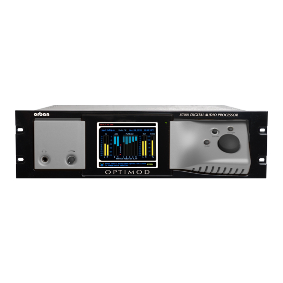
OPTIMOD-FM DIGITAL OPERATION Section 3 Operation 8700i Front Panel Headphone Jack allows you to monitor the output of the processing through head- phones. The headphones carry the same output as the rear-panel analog output: ei- ther analog-channel processing, HD processing, or low-delay monitor processing. Headphone impedance should be 75... - Page 172 AGC meters show the gain reduction of the slow AGC processing that precedes the multiband compressor. Full-scale is 25 dB gain reduction. The AGC is a two-band unit with Orban’s patented bass coupling system. The two meters indicate the gain reduction of the AGC Master and Bass bands.
-
Page 173: Introduction To Processing
OPTIMOD-FM DIGITAL OPERATION 2B HF meters display the gain reductions in dB of the independent left and right channel high frequency limiters in the 8700i’s Two-Band structure. These meters ap- pear only when the 8700i is in Two-Band mode. Out meters display the 8700i’s instantaneous peak output level. Comp meter displays the stereo encoder’s output level before the C 1 or C attenuators, using a linear percent scale over a 0% to 125% modulation range. -
Page 174: Distortion In Processing
In FM processing, there is a direct trade-off between loudness, brightness, and dis- tortion. You can improve one only at the expense of one or both of the others. Thanks to Orban’s psychoacoustically optimized designs, this is less true of Orban processors than of others. -
Page 175: Optimod-Fm-From Bach To Rock
OPTIMOD-FM DIGITAL OPERATION In the 8700i, the tradeoff between brightness and the other two parameters has been considerably improved (by 2.5 – 3 dB above 6 kHz) when an “MX” preset is ac- tive compared to when an “8500-style” preset is active. Nevertheless, all intelligent processor designers must acknowledge and work within the laws of physics as they apply to this trade-off. -
Page 176: Fundamental Requirements: High-Quality Source Material And Accurate Monitoring
CDs that this energy cannot possibly survive the FM preemphasis / de- emphasis process. Although the 8700i loses less high frequency energy than any pre- vious Orban processor (due to improvements in high frequency limiting and clipping technology), it is nevertheless no match for CDs that are mastered so bright that they will curl the vinyl off car dashboards. -
Page 177: About The 8700I's Signal Processing Features
OPTIMOD-FM DIGITAL OPERATION About the 8700i’s Signal Processing Features Dual-Mono Architecture The 8700i implements full dual-mono architecture in both the AGC and the multi- band compressor sections. You can couple each band in both the AGC and multi- band compressors to a variable extent—anywhere from perfect stereo coupling to completely uncoupled operation. -
Page 178: Multipath Mitigator" Left/Right Phase Skew Correction
Stereo Enhancement: The 8700i provides two different stereo enhancement algo- rithms. The first is based on Orban’s patented analog 222 Stereo Enhancer, which increases the energy in the stereo difference signal (L–R) whenever a transient is de- tected in the stereo sum signal (L+R). - Page 179 Figure 3-2 shows the effect of the phase correction: all 10 tones are now in-phase. Two-Band Gated AGC: The AGC is a two-band device, using Orban’s patented “mas- ter / bass” band coupling. It has an additional important feature: target-zone gat- ing.
-
Page 180: Figure 3-3: Xponential Loudness Block Diagram
622B), using a sophisticated, proprietary optimization program. The curves are matched to better than 0.15 dB. This means that their sound is very close to the sound of an Orban analog parametric. They also use very high quality filter algo- rithms to ensure low noise and distortion. - Page 181 3-11 OPTIMOD-FM DIGITAL OPERATION If input program material below 45 Hz is present, the subharmonic synthesizer au- tomatically reduces the level of the synthesized subharmonics to prevent excess build-up of energy below 45 Hz. To prevent introducing unnatural coloration in male speech. the subharmonic syn- thesizer is defeated when the automatic speech/music detector detects speech.
- Page 182 See To Override the Speech/Music Detector on page 3-73. DSP-derived Stereo Encoder: The 8700i’s stereo encoder is derived from algorithms first developed for the high-performance Orban 8218 stand-alone encoder. The 8700i’s stereo encoder operates at 512 kHz-sample rate to ease the performance re- quirements of the D/A converter’s reconstruction filter, making it possible to achieve...
- Page 183 IMIT RIVE control as usual Composite Limiter/Clipper: Orban has traditionally opposed composite clipping be- cause of its tendency to interfere with the stereo pilot tone and with subcarriers, and because it causes inharmonic aliasing distortion, particularly between the stereo main and subchannels. Protecting the pilot tone and subcarrier regions is particular- ly difficult with a conventional composite clipper because appropriate filters will not only add overshoot but also compromise stereo separation—filtering causes the sin-...
- Page 184 3-14 OPERATION ORBAN MODEL 8700i carrier protection and without adding the pumping typical of simple gain-control “look-ahead” solutions. We succeeded in our effort. The 8700i offers a patented “Half-Cosine Interpolation” composite limiter that provides excellent spectral protection of the pilot tone and SCAs (including RDS), while still providing approximately 60 dB of separation when a single-channel composite waveform is clipped to 3 dB depth.
-
Page 185: Itu-R 412 Compliance For Analog Fm Broadcasts
3-15 OPTIMOD-FM DIGITAL OPERATION ITU-R 412 Compliance for Analog FM Broadcasts ITU-R 412 requires the “average multiplex power” to be limited to a standard value. The 8700i contains a defeatable feedback multiplex power limiter that constantly monitors the multiplex power according to ITU-R 412 standards. The power control- ler automatically reduces the average modulation to ensure compliance. -
Page 186: Bs.1770 Compliance For Digital Radio
3-16 OPERATION ORBAN MODEL 8700i The peak limiter in the digital radio processing chain is a mastering-quality look- ahead limiter. This limiter minimizes IM distortion in addition to minimizing har- monic distortion. The resulting peak limiting is almost always undetectable when used with reasonable amounts of gain reduction (i.e., frequently recurring gain re-... -
Page 187: Input/Output Delay
3-17 OPTIMOD-FM DIGITAL OPERATION Input/Output Delay The sophisticated look-ahead algorithms in the 8700i have one significant cost—the input/output time delay is longer than that of an analog processor and can cause problems if an off-air pickup is used to feed talent headphones. To make intelligent decisions about how to process, the 8700i needs to look ahead at the next part of the program waveform. -
Page 188: Intermediate Modify
3-18 OPERATION ORBAN MODEL 8700i optimized by Orban’s audio processing experts on the basis of years of experience designing audio processing and upon hundreds of hours of listening tests. As you increase the setting of the L control, the air sound will become louder, but (as with any processor) processing artifacts will increase. -
Page 189: Gain Reduction Metering
3-19 OPTIMOD-FM DIGITAL OPERATION Compressor attack times and thresholds are available, along with settings affecting the automatic clipping distortion control. These controls can be exceedingly danger- ous in inexperienced hands, leading you to create presets that sound great on some program material, yet fall apart embarrassingly on other material. -
Page 190: To Delete A User Preset
3-20 OPERATION ORBAN MODEL 8700i A) Press the Escape button repeatedly until you see the main menu. B) Locate to S and press Enter. C) The S screen appears. RESET D) Choose a name for your preset. Some non-alphanumeric characters (such as < and > ) are reserved and cannot be used in preset names. -
Page 191: About The Processing Structures
3-21 OPTIMOD-FM DIGITAL OPERATION B) L to S > M icon and then press the E button. OCATE YSTEM ETUP EMORY NTER C) Locate to highlight the user preset you wish to delete. Factory presets cannot be deleted. D) L to D and then press the E button to delete the highlighted... -
Page 192: Factory Programming Presets
Unused structures operate constantly in the background, so switching between structures occurs with a seamless cross-fade. Unlike older Orban processors like the 8200, no DSP code is reloaded and no audio mute is necessary. -
Page 193: Table 3-1: Factory Programming Presets
3-23 OPTIMOD-FM DIGITAL OPERATION FACTORY PROGRAMMING PRESETS GREGG MX GREGG MX GREGG OPEN GREGG OPEN GREGG OPEN MX GREGG OPEN MX GREGG LL GREGG LL IMPACT MX IMPACT MX INSTRUMENTAL JAZZ JAZZ JAZZ MAINSTREAM 1 MX MAINSTREAM 1 MX MAINSTREAM 2 MX MAINSTREAM 2 MX MAINSTREAM 3 MX MAINSTREAM 3 MX... - Page 194 Bass, Mid EQ, and HF EQ controls. Un- ASIC ODIFY like Orban’s 8200, you can make changes in EQ (and stereo enhancement) without losing the ability to use L settings. Of course, L is still available for the unedited preset if you want to go back to it.
- Page 195 3-25 OPTIMOD-FM DIGITAL OPERATION The remaining three preset types (listed below) are identical to their counterparts in Optimod-FM 8500: If the preset has “UL” in its name, it uses the Ultra-Low Latency Five-Band struc- ture. “UL” presets are not as competitive as other presets and should only be used if you absolutely need the low delay (for off-air cueing of finicky talent, for example).
- Page 196 3-26 OPERATION ORBAN MODEL 8700i There is also a corresponding two-band preset called CLASSICAL-2B+AGC. COUNTRY: The COUNTRY-MEDIUM preset uses the ROCK-SMOOTH source preset. It has a gentle bass lift and a mellow, easy-to-listen-to high end, along with enough presence energy to help vocals to stand out. The COUNTRY-LIGHT preset uses the ROCK-LIGHT source preset.
- Page 197 3-27 OPTIMOD-FM DIGITAL OPERATION If the recordings you play are inconsistent in texture and equalization, you may pre- fer the ROCK-SMOOTH preset. ROCK-SMOOTH MX and ROCK-SOFT MX are also appropriate for this format. GOLD: GOLD is loud and “hi-fi”-sounding while still respecting the limitations and basic flavor of the recordings from the era of the 1950s through 1970s.
- Page 198 3-28 OPERATION ORBAN MODEL 8700i are excellent general-purpose presets for stations playing post-1980 recordings of various genres of popular music. IMPACT MX: IMPACT MX is intended for CHR and similar formats where attracting a large audience (maximizing cume) is more important than ensuring long time-spent- listening.
- Page 199 3-29 OPTIMOD-FM DIGITAL OPERATION This amount of bass may be excessive with certain consumer radios (particularly “boom-boxes”) that already have substantial bass boost. Use it with care. LOUD-HOT+BASS LL is the low-latency version of LOUD-HOT+BASS. LOUD+SLAM is similar to LOUD-HOT+BASS, but uses H bass clipping mode with of 7.6, a B of 18 dB/octave.
- Page 200 3-30 OPERATION ORBAN MODEL 8700i boost provides enough presence energy to ensure that vocals stand out. A modest amount of high frequency coupling (determined by the Band Clipping 3 > 4 setting) allows reasonable amounts of automatic HF equalization (to correct dull program material), while still preventing exaggerated frequency balances and excessive HF density.
-
Page 201: Equalizer Controls
3-31 OPTIMOD-FM DIGITAL OPERATION Equalizer Controls Table 3-2 on page 3-33 summarizes the equalization controls available for the Five- Band structure. These EQ controls are available in Basic Modify, Intermediate Modify and Advanced Modify screens. However, some of the control names have ab- breviated names in the Advanced Modify screen, as noted in the table. - Page 202 Low Frequency Parametric Equalizer is a specially designed parametric equalizer whose boost and cut curves closely emulate those of a classic Orban analog para- metric equalizer with conventional bell-shaped curves (within 0.15 dB worst-case). This provides warm, smooth, “analog-sounding” equalization.
-
Page 203: Table 3-2: Equalization Controls
The curves in the 8700i’s equalizer were created by a so-called “minimax” (Minimize the Maximum error, or “equal-ripple”) IIR digital approxima- tion to the curves provided by the Orban 622B analog parametric equal- izer. Therefore, unlike less sophisticated digital equalizers that use the “bilinear transformation”... - Page 204 3-34 OPERATION ORBAN MODEL 8700i range is 0.8-4.0 octaves. If you are unfamiliar with using a parametric equalizer, 1 octave is a good starting point. The audible effect of the midrange equalizer is closely associated with the amount of gain reduction in the midrange bands. With small amounts of gain reduction, it boosts power in the presence region.
- Page 205 The difference will never exceed the difference that would have other- wise occurred if the lowest frequency band were independently gated. If you are familiar with older Orban processors like the 8200, this is the maximum amount of boost that would have occurred if you had set their...
- Page 206 8700i conservatively and not attempting to achieve very high on-air loudness. You have somewhat more leeway than you do in older Orban FM proces- sors like the 8200 because the 8700i’s new distortion control will work to help prevent audible speech distortion even when the phase rotator is switched out.
-
Page 207: Stereo Enhancer Controls
The stereo enhancer is common to the FM and HD processing chains. You can oper- ate it in one of two modes or “styles.” The first emulates the Orban 222 analog ste- reo enhancer, while the second mode, called Delay, emulates a popular enhancer from another manufacturer that adds a delayed version of the L–R signal to the... -
Page 208: Xponential Loudness Controls
3-38 OPERATION ORBAN MODEL 8700i The two stereo channels are close to identical in magnitude and phase. In this case, the enhancer assumes that the program material is actually mono and thus suppresses enhancement to prevent the enhancement from exaggerating the undesired channel imbalance. -
Page 209: Agc Controls
3-39 OPTIMOD-FM DIGITAL OPERATION inaudible details. The Xponential Loudness algorithm has many hidden controls that are not available to users but instead are contained in one of six “parent presets,” which are named as colors: YELLOW, GOLD, WHITE, BLUE, RED and BLACK. Each provides a different audio texture and amount of enhancement. -
Page 210: Table 3-5: Agc Controls
(such as a CLASSICAL preset). The AGC is also ordinarily defeat- ed if you are using an external AGC (like Orban’s 6300). However, in this case it is better to defeat the AGC globally in the System Setup screen. - Page 211 3-41 OPTIMOD-FM DIGITAL OPERATION by the setting of the AGC D control, by the level at which the console VU meter RIVE or PPM is peaked, and by the setting of the MB D (compressor) control. RIVE Master AGC Release control provides an adjustable range from 0.5 dB / second (slow) to 20 dB / second (fast).
-
Page 212: Advanced Agc Controls
3-42 OPERATION ORBAN MODEL 8700i troducing obvious coloration, the gating smoothly preserves the average overall frequency response “tilt” of the multiband compressor, broadly maintaining the “automatic equalization” curve it generates for a given piece of program material. Note: If the M... - Page 213 Previous Orban AGCs had compression ratios very close to :1, which produces the most consistent and uniform sound. However, the 8700i compressor can reduce this ratio to as low as 2:1.
- Page 214 3-44 OPERATION ORBAN MODEL 8700i ting. The I control allows you to add or subtract gain from the idle gain set- ting determined by the AGC D setting. RIVE You might want to do this if you make a custom preset that otherwise causes the gain to increase or decrease unnaturally when the AGC is gat- ed.
-
Page 215: Peak Limiter Controls
3-45 OPTIMOD-FM DIGITAL OPERATION is useful if you need a crossover with low delay and no phase distortion when flat. Its downside is the possibility of coloration when the gains of the two bands are widely disparate. is a phase-linear crossover whose upper band is derived by subtracting its INEAR lower band from the crossover’s input, as passed through a delay equal to the group delay of the lowpass crossover filter. - Page 216 Composite Limit Mode determines if the composite limiter will operate as a hard clipper or as Orban’s patented “Half-Cosine Interpolation” composite limiter (which is not a clipper). When operating as a hard clipper, the composite limiter will produce maximum brightness in the frequency range from 5 to 15 kHz because, unlike the 8700i’s left/right audio-domain peak limiters, it can produce...
- Page 217 3-47 OPTIMOD-FM DIGITAL OPERATION kHz notch filter will remove the third harmonic produced by the limiting. This will cause the output level to increase. For this reason, we offer the option to use the filter to provide excellent pilot protection at the cost of a slight potential overshoot, or to defeat the filter.
- Page 218 3-48 OPERATION ORBAN MODEL 8700i around the pilot. A spectrum analyzer will reveal that, in fact, the pilot is protected by at least 60 dB in this 500 Hz wide area of the spectrum. Multiplex Offset (Multiplex Power Offset) operates only when the ITU-412 multiplex power controller is activated (and is thus irrelevant to users in countries that do not enforce this standard).
-
Page 219: 8500-Style Peak Limiter Controls
3-49 OPTIMOD-FM DIGITAL OPERATION operates the clipper like the clipper in the 8200. It produces the most har- monic distortion. This can be useful if you want maximum bass punch, because this setting allows bass transients (like kick drums) to make square waves. The peak level of the fundamental component of a square wave is 2.1 dB higher than the peak level of the flat top in the square wave. - Page 220 HAPE are only available in the Advanced Modify screen. Bass Clip Thresh sets the clipping threshold of Orban’s patented embedded bass clip- per, which is used only in the FM processing chain and not in the HD chain. The clip- per is embedded in the multiband crossover so that any distortion created by clip- ping is rolled off by part of the crossover filters.
-
Page 221: Advanced 8500-Style Peak Limiter Controls
3-51 OPTIMOD-FM DIGITAL OPERATION HF Clipping determines the amount of protection provided by the 8700i’s high fre- quency multiband clipper. This control was first introduced in the 8200 and allowed users to trade off distortion against brightness. Because of subsequent improve- ments in the clipping system, this control is much less useful than it was in the 8200 and we recommend always setting it to “0.”... - Page 222 3-52 OPERATION ORBAN MODEL 8700i The overshoot compensator works at 256 kHz sample rate and is fully an- ti-aliased. Hard Clip Shape (Hard Clip Shape) allows you to change the knee of the in- put/output gain curve of the bass clipper when B is set to H .
-
Page 223: 8700I Mx Technology Peak Limiter Controls
2.5 to 3 dB more power at high frequencies, which minimizes audible HF loss caused by preemphasis limiting. Drums and percussion cut through the mix. Highs are airy. See Measuring the Improvements in Optimod-FM 8700i’s FM Peak Limiting Technol- ogy starting on page 3-100 for a more detailed discussion. - Page 224 Because the MX peak limiter uses newly developed algorithms that differ from those used by past Orban proces- sors, the loudness/distortion/brightness/punch tradeoffs are also different and it is worthwhile to take the time to get a feel for the MX limiter’s capabilities.
-
Page 225: The Two-Band Structure
MX-style peak limiter (to achieve highest performance) or with an 8500-style peak limiter (to achieve lower delay). Like the “Two-Band Purist” structure in Orban’s OPTIMOD-FM 8200, the 8700i’s Two-Band Structure is phase-linear through- out to maximize sonic transparency. The Two-Band structure has an open, easy-to-listen-to sound that is similar to the source material if the source material is of good quality. - Page 226 3-56 OPERATION ORBAN MODEL 8700i These are the only two-band presets. To achieve the equivalent of an 8500 PROTECTION preset, use the CLASSICAL-2B preset. To achieve higher performance in protection applications, use the CLASSIC-2B MX preset instead. Classical music is traditionally broadcast with a wide dynamic range. However, with many recordings and live performances, the dynamic range is so great that the quiet passages disappear into the noise on most car, portable, and table radios.
-
Page 227: Customizing The Settings
3-57 OPTIMOD-FM DIGITAL OPERATION The five-band structure is not phase-linear, so the CLASSICAL-5 BAND preset is likely to have slightly less audible transparency than the structure. CLASSICAL T Customizing the Settings Each Two-Band Factory Preset has a L control (located in the Basic Modify screen) that adjusts on-air loudness. -
Page 228: Table 3-9: Two-Band Controls
3-58 OPERATION ORBAN MODEL 8700i ting of the 2B R control and the dynamics and level of the program material ELEASE determine the actual release time of the compressor. The action of the 2B R control has been optimized for resolution and adjusta- ELEASE bility. - Page 229 3-59 OPTIMOD-FM DIGITAL OPERATION tigue. Release in the two-band compressor automatically becomes faster as more gain reduction is applied (up to about 10 dB). This makes the pro- gram progressively denser, creating a sense of increasing loudness alt- hough peaks are not actually increasing. If the gain-riding AGC is defeat- ed (with the AGC on/off control), you can use this characteristic to pre- serve some feeling of dynamic range.
-
Page 230: Advanced Two-Band Controls
3-60 OPERATION ORBAN MODEL 8700i With the 2B R (Two-Band Release) control set to 2 dB / second, setting the 2B ELEASE control toward 0% (independent) will produce a sound that is very OUPLING open, natural, and non-fatiguing, even with large amounts of gain reduction. Such settings will provide a bass boost on some program material that lacks bass. -
Page 231: The Five-Band Structure
3-61 OPTIMOD-FM DIGITAL OPERATION 2B Clipping is a compression threshold control that affects the bass and master bands equally. It sets the drive level to the high frequency limiting and multiband distortion-controlling processing that precedes the final clipping section. The distor- tion-controlling section uses a combination of distortion-cancelled clipping and look-ahead processing to anticipate and prevent excessive clipping distortion in the final clipper. -
Page 232: Putting The Five-Band Structure On The Air
3-62 OPERATION ORBAN MODEL 8700i sets. This is too long to permit live off-air monitoring into talent headphones. This is the main reason why the 8700i offers 8500-style presets too—these presets have much lower delays than do their MX counterparts. -
Page 233: Table 3-10: Multiband Controls
3-63 OPTIMOD-FM DIGITAL OPERATION MB Drive control adjusts the signal level going into the multiband compressor and therefore determines the average amount of gain reduction in the multiband com- pressor. Range is 25 dB. Adjust the MB D control to your taste and format requirements. Used lightly RIVE with slower multiband release times, the multiband compressor produces an open, re-equalized sound. - Page 234 3-64 OPERATION ORBAN MODEL 8700i these faster release times produce more limiting action. Increasing density can make sounds seem louder, but can also result in an unattractive busier, flatter, or denser sound. It is very important to be aware of the many negative subjective side effects of excessive density when setting controls that affect the density of the processed sound.
-
Page 235: Table 3-11: Mb Attack / Release Controls
3-65 OPTIMOD-FM DIGITAL OPERATION sounds just right on music and voice when listened to on small table ra- dios, car radios, portables, or home hi-fi systems. The Medium Fast settings (MF and MF 2) are ideal for a highly com- petitive Contemporary Hit Radio (CHR) format whose ratings depend on attracting a large number of listeners (high “cume”) but which does not assume that a listener will listen to the station for hours at a time. - Page 236 3-66 OPERATION ORBAN MODEL 8700i band compressor is substantially lower (so that it operates more like a limiter than like a compressor) and the release time of the gain-riding AGC is speeded up (so that it provides compression and some increase of density).
- Page 237 3-67 OPTIMOD-FM DIGITAL OPERATION Note: If the MB G (Gate Threshold) control is turned O , the HRESH DJ B control (in the Equalization screen) is disabled. MB Clipping sets the drive level to the multiband distortion controlling processing that precedes the final clipping section. The distortion-controlling section uses a combination of distortion-cancelled clipping and look-ahead processing to antici- pate and prevent excessive clipping distortion in the final clipper.
- Page 238 3-68 OPERATION ORBAN MODEL 8700i Note also that it is virtually impossible to achieve undetectable dynamic noise reduc- tion of program material that is extremely noisy to begin with, because the program never masks the noise. It is probably wiser to defeat the dynamic noise reduction with this sort of material (traffic reports from helicopters and the like) to avoid ob- jectionable side effects.
-
Page 239: Table 3-12: Mb Band Mix Controls
3-69 OPTIMOD-FM DIGITAL OPERATION There are two sets of mixer controls, one for the analog processing chain and one for the HD processing chain. The range of the band mix controls has been purposely limited because the only gain control element after these controls is the back-end clip- ping system (including the multiband clipper / distortion controller), which can produce considerable audible distortion if overdriven. -
Page 240: Advanced Multiband And Band Mix Controls
3-70 OPERATION ORBAN MODEL 8700i velopers when they are creating new 8700i presets. The mute control for a given band affects both the FM and HD processing because it mutes the input of compres- sor in that band. This prevents the muted compressor’s sidechain from producing a gain reduction signal that could couple into unmuted bands through the various band-coupling controls. - Page 241 3-71 OPTIMOD-FM DIGITAL OPERATION Only the five-band MX presets have Band 5 A controls for the FM TTACK analog processing. In the 8500-style presets, the band 4 and band 5 com- pressors share one compression sidechain, although their associated clip- pers and downward expanders operate independently.
- Page 242 3-72 OPERATION ORBAN MODEL 8700i High Frequency Limiter sets the amount of additional gain reduction occurring in band 5 when high frequency energy would otherwise cause excessive distortion in the final clipper. It uses an analysis of the activity in the final clipper to make this de- termination and works in close cooperation with the band-5 multiband clipper.
-
Page 243: To Override The Speech/Music Detector
3-73 OPTIMOD-FM DIGITAL OPERATION Look-ahead activates or defeats the look-ahead functionality in the multiband com- pressor / limiter. Defeating look-ahead improves transient impact at the expense of distortion, particularly on speech. To mitigate this tradeoff, a selectable “auto” mode turns look-ahead on for speech material and off for music, using an automatic speech/music detector. -
Page 244: About The 8700I's Hd / Digital Radio Processing
3-74 OPERATION ORBAN MODEL 8700i C) Set the S control to S PEECH ETECT PEECH D) Save the resulting preset as a second User Preset/ You may now program two GPI inputs to recall these two presets as desired. Recall the first preset to force “music”... - Page 245 3-75 OPTIMOD-FM DIGITAL OPERATION To control excessive brightness in the HD processing when operating the HD and FM processing independently: Use little or no high frequency boost in the HD equalization section. Set Band 4>5 coupling to 100%. ...
-
Page 246: Delay Difference Between Hd And Fm Outputs
3-76 OPERATION ORBAN MODEL 8700i room to compensate for data reduction-induced peak overshoots at the receiver, which might otherwise cause clipping. In our experience, 2 dB is typically adequate. Delay Difference between HD and FM Outputs To make the receiver analog/digital crossfade free from comb filtering, the time de- lays in the HD Radio’s FM and HD channels must have a fixed and predictable offset,... -
Page 247: Hd I/O Setup Controls
3-77 OPTIMOD-FM DIGITAL OPERATION If you are using a composite output to drive the FM analog side of your transmis- sion plant, set the stereo encoder’s D control to I . This control is IVERSITY ELAY located in the C screen. -
Page 248: Table 3-13: Hd I/O Setup Controls
3-78 OPERATION ORBAN MODEL 8700i When this field is highlighted, press the Enter button to toggle between coarse and fine adjustment. In PC Remote, drag the slider of the control with the mouse to set the delay coarsely, use the Page Up and Page Down keys for intermediate incre- ments, and use the mouse wheel to fine-tune the delay in one-sample adjustment increments. -
Page 249: Digital Output
3-79 OPTIMOD-FM DIGITAL OPERATION bandwidth to 15 kHz improves subjective quality. This can occur because the codec then uses all of its bits to encode information in the most sub- jectively important part of the ear’s bandwidth. If the codec employs Spectral Band Replication®... - Page 250 3-80 OPERATION ORBAN MODEL 8700i justment allows you to ensure compatibility with downstream equipment requiring a fixed sample rate. A 32 kHz sample rate cannot represent frequencies higher than approxi- mately 15 kHz. Therefore, setting the sample rate to 32 kHz automatical- ly forces the bandwidth to 15 kHz, regardless of the setting of the HD control.
-
Page 251: Unique Hd Audio Controls
3-81 OPTIMOD-FM DIGITAL OPERATION follows the sample rate present at the selected input, regardless of the setting of the output sample rate selector. If no signal is provided to the 8700i Input or S , set SR S and select the desired output sample rate. NTERNAL Format determines if the digital-channel output channel status bits... - Page 252 3-82 OPERATION ORBAN MODEL 8700i rately. The I mode allows you to set the HD equalizer and HD multiband NDEPENDENT compressor/limiter audio controls independently of their FM counterparts. mode exposes HD controls that are hidden in FMHD mode. NDEPENDENT If a given preset has certain HD and FM controls set differently, setting the FMHD...
-
Page 253: Itu-R Multiplex Power Controller
3-83 OPTIMOD-FM DIGITAL OPERATION When setting up an HD Radio facility, set the O control to 0 dBFS. EVEL Then adjust the HD L in the on-air preset to match the loud- IMITER RIVE ness of the HD channel to the loudness of the FM channel at the receiver. In an HD Radio receiver, the HD channel has 5 dB higher gain than the analog FM channel. -
Page 254: Mpx Power Meter
3-84 OPERATION ORBAN MODEL 8700i sinewave that modulates the FM carrier to 19 kHz (25.3% modulation). Many Eu- ropean countries are now enforcing this recommendation. (See ITU-R 412 Compli- ance on page 3-15 for more information.) The BS.1770 Safety Limiter for the analog radio processing chain is located immedi- ately before the MPX power controller. -
Page 255: Figure 3-7: Multiplex Power Over 15 Minute Observation Interval With Multiplex Power Controller Active, Measured At The Optimod's Composite Output
3-85 OPTIMOD-FM DIGITAL OPERATION Recalling that the MPX POWER LEVEL meter is calibrated so that it indicates 0 dB when the composite output of the 8700i is a sinewave at –11.92615 dB below 100% modulation, we conclude that our subcarrier at 4% injection will add 0.10694 dB to the multiplex power. -
Page 256: Audio Processing And The Multiplex Power Threshold Control
3-86 OPERATION ORBAN MODEL 8700i built-in stereo encoder to drive the transmitter directly. Section 1 of this manual has an extensive discussion of overshoot in transmission paths. See page 1-15 and following pages. Many paths have overshoot and this forces you to reduce the average modulation to avoid overmodulating the transmitter. -
Page 257: About The Multiplex Power Controller's Time Constants
TRLR control is part of the active processing preset. Preset 0: No gating: Works like Orban’s older, non-gated MPX power controller. Preset 1: Only the quieter passages are gated and the gated release is faster than it is in the other presets. Created to maximize loudness within the BS.412 limit while providing more on-air dynamics and preventing unnecessary gain pump- ups. -
Page 258: Test Modes
3-88 OPERATION ORBAN MODEL 8700i Preset 4: A general-purpose preset that works well with most processing presets. When on-air processing preset is designed well, it is still possible to stay at the limit with nearly inaudible BS412 control up to 2dB gain reduction. - Page 259 3-89 OPTIMOD-FM DIGITAL OPERATION The ear is far less sensitive to bass than to midrange sounds. You can see this for yourself by examining the classic Fletcher-Munson "equal-loudness" curves. This means that if you want robust bass, this will take up a great deal of room in your modulation waveform.
-
Page 260: Bass Punch In The Mx Presets
3-90 OPERATION ORBAN MODEL 8700i distortion even on steady-state waveforms (depending on where you have set the control). LIPPER HRESH This control is the primary means of trading off bass punch against IM distortion caused the bass’ pushing non-bass material into the final clippers. Set it more nega- tive for less punch but less IM distortion. -
Page 261: Summary
By default, the installer installs a shortcut to 8700iPC.exe on your desktop and in your Start Menu under Orban\Optimod 8700i. 8700i PC Remote can control only one 8700i at a time but it can readily switch be- tween several 8700is. -
Page 262: To Set Up A New Connection
3-92 OPERATION ORBAN MODEL 8700i any 8700i that is connected directly to the PC’s serial port(s). Before your PC can communicate with a given 8700i, you must first set up a “con- nection,” which is information that allows PC Remote to locate and communicate with the 8700i. -
Page 263: To Modify A Control Setting
A window will appear saying, “Connecting to the 8700i.” A few moments later, a new message will appear: “Please Wait. Updating Local Files.” When run, the Orban PC Remote software installer makes copies of all 8700i fac- tory preset files on your local hard drive. The PC Remote software reads these files to speed up its initialization. -
Page 264: To Save A User Preset You Have Created
The encryption options prevent archived presets, system files, and auto- mation files from being restored if the user does not have the password used for the encryption. There is no “back door”— Orban cannot help you to decrypt a preset whose password is unknown. -
Page 265: To Restore Archived Presets, System Files, And Automation Files
PC Remote will request the password under which it was encrypted. All User Presets are compatible with all 8700i software versions. If Orban adds new controls to a software version, the new software will assign a reasonable default value to any control missing in an old User Preset. -
Page 266: To Share An Archived User Preset Between 8700Is
3-96 OPERATION ORBAN MODEL 8700i a) Set the F field to a user preset file type (*.orb87user, *.orbu). ILES b) Select the desired preset in the dialog box. c) Click the R button. ESTORE D) To restore all the user presets from a specific location: a) Set the F field to a user preset file type (*.orb87user, *.orbu) -
Page 267: To Group Multiple 8700Is
3-97 OPTIMOD-FM DIGITAL OPERATION Controls to set the event type and time are available on the right hand side of the dialog box. (See Using Clock-Based Automation on page 2-42 for an explanation of 8700i automation.) C) Check the E check box at the top of the dialog box to enable NABLE UTOMATION... -
Page 268: Multiple Installations Of Optimod 8700I Pc Remote
8700i PC Remote software. Each version of 8700i PC Remote has its own top-level folder, normally under \Program Files\Orban. (The default folder is \Program Files (x86)\Orban\Optimod 8700i.) When you install a new version of 8700i PC Remote, the default behavior is to overwrite the old version, which is usually the desired behavior. - Page 269 3-99 OPTIMOD-FM DIGITAL OPERATION Each version of 8700i PC Remote will display all 8700i Aliases, even those pointing to 8700is with incompatible version numbers. If you attempt to connect to an older version of 8700i from a newer version of 8700i PC Remote, 8700i PC Remote will of- fer to upgrade the software in the target 8700i so that it corresponds to the version of 8700i PC Remote that is active.
-
Page 270: White Paper: Measuring The Improvements In Optimod-Fm 8700I's Fm Peak Limiting Technology
3-100 OPERATION ORBAN MODEL 8700i White Paper: Measuring the Improvements in Optimod-FM 8700i’s FM Peak Limiting Technology Figure 3-8 Madonna, “Get Together” remix; third-octave difference Introduction The 8700i offers new “MX” peak limiter technology that decreases distortion while increasing transient punch and high frequency power handling capacity. Compared to the FM-channel peak limiter in Optimod-FM 8500, the new peak limiter typically provides 2.5 to 3 dB more power at high frequencies, which minimizes audible HF... -
Page 271: Measurements
3-101 OPTIMOD-FM DIGITAL OPERATION The 8700i’s “MX” technology peak limiter consists of two main stages—first, a pre- limiter stage to control low frequency and high frequency peaks ahead of the main peak limiter and then the main peak limiter, which uses various proprietary tech- niques to control distortion, minimize transient loss, and minimize high frequency loss. -
Page 272: Figure 3-10 Kelly Clarkson, "Because Of You" Opening
1 dB more energy in the 160 Hz band but this can easily be matched more closely if the user wants.) Distortion Control: In 1977, Orban was the first company to patent and commercial- ize a psychoacoustic model to estimate and control audible clipping distortion. The... -
Page 273: Figure 3-11 Level 42, "Starchild"
3-103 OPTIMOD-FM DIGITAL OPERATION 8700i also uses a psychoacoustic model, but in a far more sophisticated way that has some similarities to audio codec technology. Figure 3-9 on page 3-101 is a twelfth-octave ratio that compares the spectrum of the 8500 and 8700i outputs in a more detailed way than the third-octave ratio seen in Figure 3-8. -
Page 274: Figure 3-12 Simple Minds, "Alive And Kicking"
GREGG MX. To keep the comparison “apples and apples,” we used the IMPACT MX preset in the 8700i. Even with these presets, the distortion in either Orban processor was negligible compared to the effect of even modest multipath and considerably less than certain other non-Orban processors produce with this material. -
Page 275: Conclusions
3-105 OPTIMOD-FM DIGITAL OPERATION that requires suppression. By using sophisticated signal processing, the MX limiter not only avoids this problem but improves transient punch compared to the older technology. The center (under the small orange triangle) of Figure 3-12 on page 3-104 shows a snare drum hit from Simple Minds, “Alive and Kicking.”... - Page 276 3-106 OPERATION ORBAN MODEL 8700i urements have verified that the 8700i’s new limiter technology has significantly im- proved high frequency power handling capability, distortion control, and transient punch compared to Orban’s previous flagship FM processor. —Robert Orban...
-
Page 277: Section 4 Maintenance
OPTIMOD-FM DIGITAL MAINTENANCE Section 4 Maintenance Routine Maintenance The 8700i OPTIMOD-FM Audio Processor uses highly stable analog and digital cir- cuitry throughout. Recommended routine maintenance is minimal. 1. Periodically check audio level and gain reduction meter readings. Become familiar with normal audio level meter readings and with the normal performance of the G/R metering. -
Page 278: Subassembly Removal And Reinstallation
MAINTENANCE ORBAN MODEL 8700i Subassembly Removal and Reinstallation See page 6-37 for the Circuit Board Locator and Basic Interconnections diagram. 1. Removing the Top Cover. To access the main boards, power supply board or display assembly, you must remove the top cover. - Page 279 OPTIMOD-FM DIGITAL MAINTENANCE G) Remove the six Phillips screws holding the DSP board to the bottom of the chassis. H) Remove the DSP board. 4. Removing the Front Panel. To service the headphone amplifier, the color LCD display, the pushbuttons, or the rotary encoder, it is first necessary to remove the front panel assembly.
- Page 280 MAINTENANCE ORBAN MODEL 8700i screw partially blocked by the rotary encoder’s knob, use a small screwdriver and attack the screw head from a slight angle, avoiding the edge of the knob to pre- vent cosmetic damage. The pushbutton switches, joystick, and rotary encoder are all soldered to this board and can be replaced by normal solder rework techniques.
- Page 281 OPTIMOD-FM DIGITAL MAINTENANCE C) Unplug any ribbon cables from the Display Interface Board, which now can be removed completely. Refer to step (8.C)to disconnect the 33-conductor ribbon cable to J103. 12. Removing the Base Board. You must have completed steps 9, 10, and 11 first. A) Make sure that AC power is disconnected from the 8700i.
-
Page 282: Field Audit Of Performance
MAINTENANCE ORBAN MODEL 8700i 18. Reassembling the Color LCD Display and carrier board. Referring to step 8, follow the instructions in reverse. Verify that pin one of the ribbon cables (red stripe) is oriented correctly. Pin 1 is indicated by the number “1” or a square pad. - Page 283 OPTIMOD-FM DIGITAL MAINTENANCE Accurate to ±0.1%. Oscilloscope DC-coupled, triggered sweep, with 5 MHz or greater vertical bandwidth. Two 620 ±5% resistors. Optional: Audio Precision APx It is assumed that the technician is thoroughly familiar with the operation of this equipment.
-
Page 284: Table 4-1: Decoder Chart For Power Supervisor
MAINTENANCE ORBAN MODEL 8700i Set Input to .................. analog Analog Ref. Level ..............+4.0 dBu Clip Level ................. +20.0 dBu Right Channel Balance ..............0.0 dB DI REF VU................15.0 dBFS c) Navigate to the I 1 screen, Set controls as in the table >... - Page 285 OPTIMOD-FM DIGITAL MAINTENANCE Your Optimod constantly monitors the dual-redundant power supplies with au- tomatic switching. If both supplies are good and connected to the AC line, the front-panel power light will glow green. If either supply has been disconnected from the AC line or has failed, the power light will be red and will flash on and off.
- Page 286 4-10 MAINTENANCE ORBAN MODEL 8700i B) Be sure you are still in BYPASS mode [see step (3.F)]. C) Connect the oscillator to the Left Analog Input XLR connector. D) Inject the Analog Input XLR connector with a level of 0 dBu (20 dB below the setting) with the oscillator set to 100 Hz.
- Page 287 4-11 OPTIMOD-FM DIGITAL MAINTENANCE I) Disconnect the oscillator and THD analyzer from the 8700i. 6. Test Digital Sample Rate Converter (Receiver). A) Verify 8700i software controls are set to their default settings. (Refer to page 4-7.) B) Be sure you are still in BYPASS mode [see step (3.F)]. C) Navigate to I .
- Page 288 4-12 MAINTENANCE ORBAN MODEL 8700i NOTE: The recommended Belar monitor is the only instrument we have encountered that can accurately measure the performance of the 8700i’s stereo encoder. With most older-technology monitors, you will be meas- uring the performance of the monitor, not the 8700i’s encoder. Of course, we have not evaluated every monitor on the market.
- Page 289 4-13 OPTIMOD-FM DIGITAL MAINTENANCE P) Measure pilot tone frequency: With the M still set to 0.0%, connect a EVEL frequency counter to either of the 8700i’s composite outputs. Verify that the pilot tone frequency is 19,000 Hz 1 Hz. 9. Optional tests. A) You can test each GPI input for functionality in the obvious way, by pro- gramming a function for it and then verifying that the function executes when you activate the input.
-
Page 291: Section 5 Troubleshooting
OPTIMOD-FM DIGITAL TROUBLESHOOTING Section 5 Troubleshooting Problems and Potential Solutions Always verify that the problem is not the source material being fed to the 8700i, or in other parts of the system. RFI, Hum, Clicks, or Buzzes A grounding problem is likely. Review the information on grounding on page 2-12. The 8700i has been designed with very substantial RFI suppression on its analog and digital input and output ports, and on the AC line input. -
Page 292: Audible Distortion On-Air
Because of its 64 kHz base sample rate, the output bandwidth of the 8700i’s FM channel processing is slightly higher (17 kHz) than that of Orban processors using 32 kHz base sample rate. The signal path to the transmitter must be essentially flat to 17 kHz to take advantage of the 8700i’s excellent peak control at its digital and ana-... -
Page 293: Audible Noise On Air
STL may only be 70-75 dB. In this case, it is wise to use an Orban studio level control device like the 8200ST Stu- dio AGC to perform the AGC function prior to the STL transmitter and to control the... -
Page 294: Whistle On Air, Perhaps Only In Stereo Reception
TROUBLESHOOTING ORBAN MODEL 8700i transmission system. An uncompressed digital STL will perform much better than any analog STL. (See Studio-Transmitter Link, starting on page 1-15.) Whistle on Air, Perhaps Only in Stereo Reception The most likely cause is oscillation in the analog input or output circuitry. If the oscil- lation is in the output circuitry and is between 23 and 53 kHz, it will be detected in a receiver’s stereo decoder and translated down into the audible range. -
Page 295: Shrill, Harsh Sound
OPTIMOD-FM DIGITAL TROUBLESHOOTING Amplitude modulation of the carrier that is synchronous with the program (“syn- chronous AM”) can cause program-related crosstalk into subcarriers. Synchronous AM should be better than 35 dB below 100% modulation as measured on a syn- chronous AM detector with standard FM de-emphasis (50s or 75s). The subcarrier receiver itself must receive a multipath-free signal and must have a wide and symmetrical IF passband and a linear, low-distortion FM demodulator to prevent program-related crosstalk into subcarriers. -
Page 296: System Will Not Pass Emergency Alert System ("Eas" Usa Standard) Tones At The Legally Required Modulation Level
First, verify that a problem really exists by using a second frequency-measuring de- vice and/or verifying the problem with a monitoring service. If the problem is real, contact Orban Customer Service; there is no frequency trim available. The crystal is a surface-mount part and is not easily field-replaceable. -
Page 297: Digital Radio Loudness Cannot Be Set Using The Digital Output 100% Peak Level Control
OPTIMOD-FM DIGITAL TROUBLESHOOTING Do not match levels by adjusting the output level of the output driving the HD ex- citer. Only use this control to match the peak levels of the Optimod output to the exciter. In other words, if the exciter is set to clip when it receives at –3 dBFS, adjust the Optimod output level to –3 dBFS. -
Page 298: Bs.1770 Safety Limiter Produces Too Much Gain Reduction
TROUBLESHOOTING ORBAN MODEL 8700i tion. Such users must fully understand the material in Section 3 of this manual to achieve the best results from this exercise. Compared to competitive processors, the 8700i offers a uniquely favorable set of trade-offs between loudness, brightness, distortion, and build-up of program densi- ty. -
Page 299: You Cannot Access The Internet After Making A Direct Or Modem Connection To The 8700I
OPTIMOD-FM DIGITAL TROUBLESHOOTING You may have the wrong interface type set on your 8700i. Navigate to S > ETUP and check the interface & R > N ETWORK EMOTE ETWORK ERIAL NTERFACE setting. If you are connecting via Direct Serial Connection or modem, review the Proper- ties you have set on that connection. -
Page 300: Troubleshooting Ic Opamps
Technical Support If you require technical support, contact Orban customer service using the infor- mation found at http://www.orban.com/contact/. Be prepared to describe the prob- lem accurately. Know the serial number of your 8700i this is printed on the rear panel of the unit. -
Page 301: Shipping Instructions
Re- turned units will be returned C.O.D. if the unit is not under warranty. Orban will pay return shipping if the unit is still under warranty. In all cases, the customer pays transportation charges to the factory (which are usually quite nominal). -
Page 303: Section 6 Technical Data
OPTIMOD-FM DIGITAL TECHNICAL DATA Section 6 Technical Data Specifications It is impossible to characterize the listening quality of even the simplest limiter or compressor based on specifications, because such specifications cannot adequately describe the crucial dynamic processes that occur under program conditions. There- fore, the only way to evaluate the sound of an audio processor meaningfully is by subjective listening tests. -
Page 304: Installation
TECHNICAL DATA ORBAN MODEL 8700i Installation Delay Defeatable Analog FM Processing delay: 0.27 to 12.0 seconds, adjustable in one-sample increments at 64 kHz sample rate to allow the delays of the analog and digital paths in the HD Radio system to be matched at the receiver output. To avoid introducing artifacts in the analog FM path, its delay is held constant and HD delay is varied if the adjustment does not exceed ±1.3 seconds. - Page 305 OPTIMOD-FM DIGITAL TECHNICAL DATA Signal-to-Noise: > = 90 dB unweighted (Bypass mode, de-emphasized, 20 Hz - 15 kHz bandwidth, referenced to 100% modulation). Crosstalk: <= –70 dB, 20 Hz - 15 kHz. Distortion: <= 0.01% THD (Bypass mode, de-emphasized) 20 Hz - 15 kHz bandwidth. Connectors: Two XLR-type, male, EMI-suppressed.
- Page 306 TECHNICAL DATA ORBAN MODEL 8700i Digital Sync Input Configuration: Used for synchronization of either or both AES3 signals to an external ref- erence provided at this input. Sampling Rate: 32 kHz, 44.1 kHz, 48 kHz, 88.2 kHz, and 96 kHz, automatically selected.
- Page 307 OPTIMOD-FM DIGITAL TECHNICAL DATA Pilot Protection: 60 dB relative to 9% pilot injection, ±250 Hz (up to 2 dB composite pro- cessing drive). Subcarrier Protection (60-100 kHz): > = 70 dB (referenced to 100% modulation; with up to 2 dB composite limiting drive; measured with 800 line FFT analyzer using “maximum peak hold ”...
- Page 308 TECHNICAL DATA ORBAN MODEL 8700i Number of Output Channels Supported: Two stereo pairs. Sample Rate: 44.1, 48, 88.2 and 96 kHz. Networking: Two RJ45 Ethernet connectors for connection to dedicated audio-over-IP LANs (supports DANTE redundancy). These connections are independent of the Opti- mod’s main Remote Computer Interface and have their own IP and MAC addresses.
-
Page 309: Circuit Description
RFI / EMI: Tested according to Cenelec procedures. Shipping Weight: 40 lbs. / 18.1 kg Warranty Five Years, Parts and Service: Subject to the limitations set forth in Orban’s Standard Warranty Agreement (page 1-30). Because engineering improvements are ongoing, specifications are subject to change with- out notice. -
Page 310: Control Circuits
2 seconds until the DSP code download has finished. If you hear a 2-second audio mute on air, you can assume that the 8700i has rebooted for some reason. Be prepared to convey this fact to Orban customer service if you call for technical assistance. -
Page 311: Input Circuits
Located on base board A remote interface connector and circuitry implements remote control of certain operating modes; OPTIMOD-FM 8700i has eight remote contact closure inputs. A valid remote signal is a momentary pulse of current flowing through remote signal pins. Current must flow consistently for 50msec for the signal to be inter- preted as valid. -
Page 312: Output Circuits
6-10 TECHNICAL DATA ORBAN MODEL 8700i Note that the small RFI “tee” filter assemblies connected to the input and output connectors are socketed and user-replaceable. Component-Level Description: The left channel balanced audio input signal is applied to the filter / load net- work made up of L100-103 and associated resistors and capacitors. - Page 313 6-11 OPTIMOD-FM DIGITAL TECHNICAL DATA put sample rate converter (SRC). The digital-to-analog (D / A) converter converts the digital audio words generated by the DSP to analog audio. High-speed D/A convert- ers do the same for the composite outputs, each of whose outputs is smoothed by a passive LC reconstruction filter.
- Page 314 6-12 TECHNICAL DATA ORBAN MODEL 8700i are socketed for easy field replacement. All other circuitry is surface-mounted. The corresponding right channel circuitry is functionally identical to that just described. 3. Digital Sample Rate Converter (SRC) and Output Transmitter Located on Input/output board...
-
Page 315: Dsp Circuit
During system initialization, the SC520 queries the DSP hardware about its opera- tional status and will display an error message on-screen if the DSP fails to initialize normally. Please note any such messages and be ready to report them to Orban Cus- tomer Service. -
Page 316: Audio-Over-Ip Module
Optimod’s Dante carrier board. (Refer to the parts locator diagram on page 6-78 and the schematics on pages 6-81 and 6-82.) If this chip fails, it must be replaced with an exact replacement from Orban. Streaming Server The streaming server is built using a Raspberry Pi microcomputer module, which is mounted on and plugged into the Auxiliary I/O Board. - Page 317 6-15 OPTIMOD-FM DIGITAL TECHNICAL DATA composite isolation transformer CMOS complementary metal-oxide semiconductor COFDM Coded Orthogonal Frequency Division Multiplex—a robust type of digital modulation using many narrow-bandwidth, low data rate, mutually non-interfering carriers to achieve an ag- gregate high data rate with excellent multipath rejection. serial data communications port D/A (or D to A) digital-to-analog converter...
-
Page 318: Parts List
Reference designator (e.g., C3, R78, IC14) Orban part number (Use reference designator if Orban Part # is not shown) Brief description of part Model, serial, and “M” (if any) number of unit see rear-panel label... -
Page 319: Base Board
6-17 OPTIMOD-FM DIGITAL TECHNICAL DATA To facilitate future maintenance, parts for this unit have been chosen from the cata- logs of well-known manufacturers whenever possible. Most of these manufacturers have extensive worldwide distribution and can be contacted through their web sites. Base Board BASE BOARD PART #... - Page 320 6-18 TECHNICAL DATA ORBAN MODEL 8700i BASE BOARD PART # DESCRIPTION COMPONENT IDENTIFIER 24635.000.01 IC 74HCT374 24900.000.01 IC, HEX INVERTER, SMT U11, U13 24967.000.01 IC, 74ACT245DW U3, U5 24978.000.01 IC, 74ACT244SC U14, 15 24979.000.01 IC, BAT54C-7 D13, 14, 15, 16, 17 24982.000.01...
-
Page 321: Cpu Board
6-19 OPTIMOD-FM DIGITAL TECHNICAL DATA CPU board CPU BOARD PART # DESCRIPTION COMPONENT, IDENTIFIER 20128.010.01 RESISTOR, 10Ω,0805 R31, R34 20128.022.01 RESISTOR, 22Ω 1% 0805 R5, R6 20128.332.01 RESISTOR, 33.2Ω,0805 R10, R11, R14 20128.499.01 RESISTOR, 49.9Ω 1% 0805 R19, R20, R21, R22, R23 20129.160.01 RESISTOR, 160Ω... -
Page 322: Rs-232 Board
6-20 TECHNICAL DATA ORBAN MODEL 8700i CPU BOARD PART # DESCRIPTION COMPONENT, IDENTIFIER 24543.000.01 IC CY2305 0DLYBuF 8P IC NM93C46 SEEPROM 24544.000.01 TSSOP 24653.000.01 IC PWRST MIC8114 SOT143 24670.000.01 IC 10 / 100BT NIC NATIONAL 24965.000.01 IC,74ALVC164245DGG U7, U8, U9 IC MICROPROCESSOR 24972.520.01... -
Page 323: Input/Output (I/O) Board
6-21 OPTIMOD-FM DIGITAL TECHNICAL DATA Input/Output (I/O) Board INPUT/OUTPUT BOARD PART # DESCRIPTION COMPONENT, IDENTIFIER 27401.000.01.1 CONN JUMPER RECPT BLACK J1:1-2, J2:3-4, J3-3-4 S-L201, S-L202, S-L203, S-L204, S-L301, S- 27408.003.01.1 CONN 3PIN SCKT STRIP L302, S-L303, S-L304, S-L401, S-L402, S- L405, S-L406 27147.008.01.1 IC SCKT DIP 8 PIN DUAL... - Page 324 6-22 TECHNICAL DATA ORBAN MODEL 8700i INPUT/OUTPUT BOARD PART # DESCRIPTION COMPONENT, IDENTIFIER C402, C403, C404, C602, C603, C604, 21194.103.01.1 CAP CER 0.01UF 25V 0402 C605, C735 20169.153.01.1 RES 1.5K OHM 1/16W 0402 R215, R216, R217, R218 29552.000.01.1 IND POWER 1.5UH 9A SMD L705 24348.000.01.1...
- Page 325 6-23 OPTIMOD-FM DIGITAL TECHNICAL DATA INPUT/OUTPUT BOARD PART # DESCRIPTION COMPONENT, IDENTIFIER R207, R208, R209, R210, R211, R212, 20130.499.01.1 RES R0805 4.99K 1% 1/8W R213, R214, R411, R412, R417, R418, R421, R423, R616, R617, R618, R705 20130.200.01.1 RES 2.00K 0805 R413, R414, R848 20129.301.01.1 RES 301 OHM 0805...
-
Page 326: Auxiliary Input/Output Board
6-24 TECHNICAL DATA ORBAN MODEL 8700i INPUT/OUTPUT BOARD PART # DESCRIPTION COMPONENT, IDENTIFIER R419, R420, R706, R713, R714, R832, 20131.100.01.1 RES 10K 0805 R833, R834, R835, R836, R837, R838, R839, R840, R841, R842, R843, R844 R317, R318, R319, R320, R321, R322, 20130.845.01.1... - Page 327 6-25 OPTIMOD-FM DIGITAL TECHNICAL DATA AUX I/O BOARD PART # DESCRIPTION COMPONENT, IDENTIFIER C222, C223, C224, C225, CAP_POL,10UF,10%,16V,TANT,3528 C226, C227, C228, C229, C320, C322 C268, C269, C270, C271, CAP,CER,NPO,0805,1%,50V,100PF,SMT C272, C273 CAP,CER,100V,47PF,5%,SMT C274, C275 C301, C302, C305, C420, CAP 1.0UF 10% 10V X5R 0402 C421, C422, C423, C435, C450, C613 C303, C304, C306, C307,...
- Page 328 6-26 TECHNICAL DATA ORBAN MODEL 8700i AUX I/O BOARD PART # DESCRIPTION COMPONENT, IDENTIFIER NXP MK64FN1M0VMD12 with Ultimo Sw IC401 – Factory Pre-Programmed 7 Port Gigabit AVB Switch IC402 Clock Generator 8 Outputs IC403 - Factory Pre-Programmed 256kb I2C CMOS Serial EEPROM IC404 1.8V Step-Down DC-DC Converter...
- Page 329 6-27 OPTIMOD-FM DIGITAL TECHNICAL DATA AUX I/O BOARD PART # DESCRIPTION COMPONENT, IDENTIFIER 0805 Thick Film Chip Resistors 1/8watt 402ohms 20130.400.01.1 R200 1% 100PPM RES,MF,1/8W,1%,475OHM R201 0805 Thick Film Chip Resistors 1/8watt 619ohms 20132.619.01.1 R202, R203 R206, R207, R208, R209, R513, R514, R515, R516, RES,MF,1/8W,1%,49.9OHM R517, R518, R519, R604,...
-
Page 330: Dsp Board
6-28 TECHNICAL DATA ORBAN MODEL 8700i DSP Board DSP BOARD PART # DESCRIPTION COMPONENT IDENTIFIER 44129.100.01 FIRMWARE FPGA J703 86xx DSP IN, CIRCUIT, PROG, -, IC703 27401.000.01 CONNECTOR JUMPER RECPT BLACK J705, (PIN, 1-2) 27468.006.01 CONNECTOR 6P MOLEX PCMNT J901 24943.000.01... - Page 331 6-29 OPTIMOD-FM DIGITAL TECHNICAL DATA DSP BOARD PART # DESCRIPTION COMPONENT IDENTIFIER 24793.000.01 IC MT48LC2M32B2P-6 IC401, IC402, IC907, IC908, IC909 24649.000.01 IC SN74AC11D AND-GATE IC301, IC302, IC603 22104.000.01 DIODE SCHOT RECT 1N5818 CR802 22083.068.01 DIODE VLTG SUPRSR 6.8 VL CR801 22083.033.01 DIODE VLTG SUPRSR 33 VLT CR803...
-
Page 332: Interface Board
6-30 TECHNICAL DATA ORBAN MODEL 8700i DSP BOARD PART # DESCRIPTION COMPONENT IDENTIFIER C231, C232, C233, C234, C235, C236, C237, C238, C239, C241, C242, C243, C244, C245, C246, C247, C248, C249, C251, C252, C253, C254, C255, C256, C257, C258, C259, C261, C262, C263,... -
Page 333: Headphone Board
6-31 OPTIMOD-FM DIGITAL TECHNICAL DATA INTERFACE BOARD PART # DESCRIPTION COMPONENT IDENTIFIER CONNECTOR SOCKET PC104 27373.040.01 J100 STACKING CONNECTOR SOCKET PC104 27373.064.01 J101, J102 STACKING HEADER PIN 2X8 RIGHT- 27414.016.01 J200 ANGLE CONNECTOR, HOUSING, RT 27756.000.01 J105 AGL SMT CONNECTOR, FPC, 33PIN ROT- 27757.033.01 J103 LOCK... -
Page 334: Encoder Board
6-32 TECHNICAL DATA ORBAN MODEL 8700i Encoder Board ENCODER BOARD PART # DESCRIPTION COMPONENT IDENTIFIER 15061.003.01 LED MOUNT, T-1, 0.220 LEDMNT 21129.410.01 CAPACITOR, AXL LDS, 0.1uF, 50V, 20% 25122.000.01 LED, T 1 3/4 RED/GRN LED, 1 26088.000.01 ENCODER, ROTARY, NOBLE 8700i 26128.000.01... - Page 335 6-33 OPTIMOD-FM DIGITAL TECHNICAL DATA POWER SUPPLY DISTRIBUTION PART # DESCRIPTION COMPONENT IDENTIFIER Resistor 0805 210Ω 1% 1/8W 20129.210.01.1 R26, R27, R29, R46, R47, R48 24789.000.01.1 IC Inverter 2-6V SINGLE CMOS SOT U11, U12 21137.447.01.1 Capacitor .47UF 25V 10% 1206 Transistor PNP MMBT3906 40V 23217.000.01.1 Q12, Q15...
-
Page 336: Schematics And Parts Locator Drawings
6-34 TECHNICAL DATA ORBAN MODEL 8700i POWER SUPPLY DISTRIBUTION PART # DESCRIPTION COMPONENT IDENTIFIER C1, C2, C3, C4, C7, C12, C13, C16, 21139.000.01.1 Capacitor X7R 0.1UF 10% 0805 C18, C19, C25, C26, C31, C34, C36, C37, C38, C39, C40 Resistor 10Ω 0805 20128.010.01.1... - Page 337 6-35 OPTIMOD-FM DIGITAL TECHNICAL DATA Function Description Drawing Page Contains: Ethernet Schematic 1 of 5 6-44 General Purpose Bus Schematic 2 of 5 6-45 Memory Schematic 3 of 5 6-46 Miscellaneous Functions Schematic 4 of 5 6-47 Power and Ground Distribution Schematic 5 of 5 6-48 RS-232 Board...
- Page 338 6-36 TECHNICAL DATA ORBAN MODEL 8700i Function Description Drawing Page Aux I/O Board Aux !/O Board Parts Locator 6-78 Contains: Drawing Interconnects Schematic 1 of 6 6-79 SCA Inputs, Sync & Schematic 2 of 6 6-80 Digital Composite Dante SRC & CPLD...
- Page 339 6-37 OPTIMOD-FM DIGITAL TECHNICAL DATA...
- Page 340 6-38 TECHNICAL DATA ORBAN MODEL 8700i...
- Page 341 6-39 OPTIMOD-FM DIGITAL TECHNICAL DATA...
- Page 342 6-40 TECHNICAL DATA ORBAN MODEL 8700i...
- Page 343 6-41 OPTIMOD-FM DIGITAL TECHNICAL DATA...
- Page 344 6-42 TECHNICAL DATA ORBAN MODEL 8700i...
- Page 345 6-43 OPTIMOD-FM DIGITAL TECHNICAL DATA...
- Page 346 6-44 TECHNICAL DATA ORBAN MODEL 8700i...
- Page 347 6-45 OPTIMOD-FM DIGITAL TECHNICAL DATA...
- Page 348 6-46 TECHNICAL DATA ORBAN MODEL 8700i...
- Page 349 6-47 OPTIMOD-FM DIGITAL TECHNICAL DATA...
- Page 350 6-48 TECHNICAL DATA ORBAN MODEL 8700i...
- Page 351 6-49 OPTIMOD-FM DIGITAL TECHNICAL DATA...
- Page 352 6-50 TECHNICAL DATA ORBAN MODEL 8700i...
- Page 353 6-51 OPTIMOD-FM DIGITAL TECHNICAL DATA...
- Page 354 6-52 TECHNICAL DATA ORBAN MODEL 8700i...
- Page 355 6-53 OPTIMOD-FM DIGITAL TECHNICAL DATA...
- Page 356 6-54 TECHNICAL DATA ORBAN MODEL 8700i...
- Page 357 6-55 OPTIMOD-FM DIGITAL TECHNICAL DATA...
- Page 358 6-56 TECHNICAL DATA ORBAN MODEL 8700i...
- Page 359 6-57 OPTIMOD-FM DIGITAL TECHNICAL DATA...
- Page 360 6-58 TECHNICAL DATA ORBAN MODEL 8700i...
- Page 361 6-59 OPTIMOD-FM DIGITAL TECHNICAL DATA...
- Page 362 6-60 TECHNICAL DATA ORBAN MODEL 8700i...
- Page 363 6-61 OPTIMOD-FM DIGITAL TECHNICAL DATA...
- Page 364 6-62 TECHNICAL DATA ORBAN MODEL 8700i...
- Page 365 6-63 OPTIMOD-FM DIGITAL TECHNICAL DATA...
- Page 366 6-64 TECHNICAL DATA ORBAN MODEL 8700i...
- Page 367 6-65 OPTIMOD-FM DIGITAL TECHNICAL DATA...
- Page 368 6-66 TECHNICAL DATA ORBAN MODEL 8700i...
- Page 369 6-67 OPTIMOD-FM DIGITAL TECHNICAL DATA...
- Page 370 6-68 TECHNICAL DATA ORBAN MODEL 8700i...
- Page 371 6-69 OPTIMOD-FM DIGITAL TECHNICAL DATA...
- Page 372 6-70 TECHNICAL DATA ORBAN MODEL 8700i...
- Page 373 6-71 OPTIMOD-FM DIGITAL TECHNICAL DATA...
- Page 374 6-72 TECHNICAL DATA ORBAN MODEL 8700i...
- Page 375 6-73 OPTIMOD-FM DIGITAL TECHNICAL DATA...
- Page 376 6-74 TECHNICAL DATA ORBAN MODEL 8700i...
- Page 377 6-75 OPTIMOD-FM DIGITAL TECHNICAL DATA...
- Page 378 6-76 TECHNICAL DATA ORBAN MODEL 8700i...
- Page 379 6-77 OPTIMOD-FM DIGITAL TECHNICAL DATA...
- Page 380 6-78 TECHNICAL DATA ORBAN MODEL 8700i...
- Page 381 6-79 OPTIMOD-FM DIGITAL TECHNICAL DATA...
- Page 382 6-80 TECHNICAL DATA ORBAN MODEL 8700i...
- Page 383 6-81 OPTIMOD-FM DIGITAL TECHNICAL DATA...
- Page 384 6-82 TECHNICAL DATA ORBAN MODEL 8700i...
- Page 385 6-83 OPTIMOD-FM DIGITAL TECHNICAL DATA...
- Page 386 6-84 TECHNICAL DATA ORBAN MODEL 8700i...
- Page 387 6-85 OPTIMOD-FM DIGITAL TECHNICAL DATA...
- Page 388 6-86 TECHNICAL DATA ORBAN MODEL 8700i...
- Page 389 6-87 OPTIMOD-FM DIGITAL TECHNICAL DATA...
- Page 390 6-88 TECHNICAL DATA ORBAN MODEL 8700i EQ CONTROLS TRACK SETTINGS OF FM ANALOG PROCESSING EQ CONTROLS EQUALIZER ULTRA-LOW 5-BAND 5-BAND LATENCY HF ENHANCER LIMITER DISTORTION- COMPRESSOR CANCELLED CLIPPER MONITOR LIMITER DRIVE LOW-DELAY MONITOR PROCESSOR FROM MAIN FM MPX POWER CONTROLLER...
Need help?
Do you have a question about the OPTIMOD-FM 8700i and is the answer not in the manual?
Questions and answers