Table of Contents
Advertisement
Quick Links
Download this manual
See also:
Operating Manual
Advertisement
Table of Contents
Troubleshooting

Subscribe to Our Youtube Channel
Related Manuals for Orban OPTIMOD 6300


Summary of Contents for Orban OPTIMOD 6300
- Page 1 Operating Manual OPTIMOD 6300 Digital Multipurpose Audio Processor Version 1.1 Software...
- Page 2 European Parliament, this product must not be discarded into the municipal waste stream in any of the Member States. This product may be sent back to your Orban dealer at end of life where it will be reused or recycled at no cost to you.
-
Page 3: Important Safety Instructions
IMPORTANT SAFETY INSTRUCTIONS All the safety and operating instructions should be read before the appliance is operated. Retain Instructions: The safety and operation instructions should be retained for future reference. Heed Warnings: All warnings on the appliance and in the operating instructions should be adhered to. Follow Instructions: All operation and user instructions should be followed. - Page 4 Safety Instructions (German) Gerät nur an der am Leistungsschild vermerkten Spannung und Stromart betreiben. Sicherungen nur durch solche, gleicher Stromstärke und gleichen Abschaltverhaltens ersetzen. Sicherungen nie überbrücken. Jedwede Beschädigung des Netzkabels vermeiden. Netzkabel nicht knicken oder quetschen. Beim Abziehen des Netzkabels den Stecker und nicht das Kabel enfassen.
- Page 5 (2) Check the other sections of the Manual (consult the Table of Contents and Index) to see if there might be some sug- gestions regarding your problem. (3) After reading the section on Factory Assistance, you may call Orban Customer Service for advice during normal Cali- fornia business hours. The number is (1) 510 / 351-3500.
- Page 6 20,000 volts. This is the spark or shock you may have felt when touching a doorknob or some other conductive surface. A much smaller static discharge is likely to destroy one or more of the CMOS semiconductors employed in OPTIMOD 6300. Static damage will not be covered under warranty.
- Page 7 Operating Manual OPTIMOD 6300 Digital Multipurpose Audio Processor Version 1.1 Software...
-
Page 8: Table Of Contents
OPTIMOD 6300 ..................1-9 OCATION OF At the transmitter is best ....................1-9 Where access to the transmitter is not possible ............. 1-9 OPTIMOD 6300 at the transmitter: gain control before the STL ......... 1-10 OPTIMOD 6300 ..........1-10 SING AS A... - Page 9 Grounding........................2-8 Power Ground......................2-8 Circuit Ground ......................2-9 ) ............2-9 TUDIO EVEL ONTROLLER NSTALLATION OPTIONAL If you are using Orban 8200ST Studio Level Controller........2-9 Figure 2-3: 8200ST Jumper Settings (*Factory Configuration) ........2-10 .........................2-12 UICK ETUP I/O S ..................2-20 NALOG AND IGITAL ETUP 6300’...
- Page 10 Distortion in Processing ....................3-3 Loudness and Distortion ....................3-3 Processing for Low Bit Rate Codecs................. 3-4 Speech/Music Detector..................... 3-5 Optimod 6300 in Radio-Oriented Applications: From Bach to Rock ....3-5 Sound-for-Picture Applications: Controlling Dynamic Range ......3-6 6300’ ..............3-6 BOUT THE...
- Page 11 : ..................3-62 UTOMATION To group multiple 6300s: ..................3-62 Navigation Using the Keyboard ................3-63 To Quit the Program....................3-63 About Aliases created by Optimod 6300 PC Remote Software ......3-63 Multiple Installations of Optimod 6300 PC Remote ...........3-63 6300 ............3-65 SING THE RODUCTION AND...
- Page 12 Legally Required Modulation Level ................5-4 System Receiving 6300’s Digital Output Will Not Lock ..........5-4 AES Channel Status Bits Will Not Set the 6300 to Stereo or Dual-Mono Mode.... 5-5 Equipment Receiving the 6300’s AES Output Changes Operation Mode Unexpectedly 5- General Dissatisfaction with Subjective Sound Quality..........
-
Page 13: Index
Function Description Drawing Page Circuit Board Locator and Basic In- Top view Chassis 6-21 terconnections (not to scale) Control board Control microprocessor. Services Parts Locator 6-22 front panel, serial port, Ethernet, Drawing and DSP+I/O board. Contains: General Purpose bus, address de- Schematic 1 of 5 6-23 coder, DSP, and I/O interface... - Page 14 bass attack control 3- · 37 bass coupling control 3- · 35 B5 down expand 3- · 53 bass release control 3- · 37 backing up presets 3- · 60 bass threshold control 3- · 36 balance adjust 2- · 22 control list 3- ·...
- Page 15 Classical music 3- · 21 crossover cleaning front panel 4- · 1 allpass 3- · 37 linear phase 3- · 38 clipper modes 3- · 37 control list 3- · 38 crossover Ethernet cable 5- · 6 clipper, bass 3- · 8 clipping 3- ·...
-
Page 16: Input
test tones 1- · 22 gate 3- · 34 easy setup 2- · 12 gate LED 3- · 2 equalizer Gateway 2- · 44, 58 bass shelf 3- · 27 gateway address 2- · 37 control list 3- · 26, 65 getting inside the unit 4 ·... - Page 17 line-up 1- · 18 line-up tones input meters 1- · 19 system will not pass at 100% modulation 5- · input meters 3- · 2 input selector line-up tones 1- · 19 I/O setup 2- · 21 Lo Pass control 3- · 31 input/output board location 1- ·...
- Page 18 1- · 21 recovering from lost 2- · 34 network timeserver 2- · 38 Orban installer program 2- · 43 networking 2- · 36 PC board locator diagram 6- · 21 News format 3- · 23 PC control NEXT button 3- ·...
- Page 19 1- · 3 power supply structures 3- · 14 circuit description 6- · 10 two-band purist 30 · 9 Orban part # 6- · 11 video oriented 3- · 6 testing 4- · 8 processing structures power supply board two-band 3- ·...
- Page 20 processing 3- · 6 routine maintenance 4- · 1 spare parts RS232 obtaining 6- · 13 testing 4- · 11 specifications 6- · 1 RS-232 connector 2- · 5 speech/music detector 3- · 5 RS-232 interface Sports format 3- · 23 circuit description 6- ·...
- Page 21 creating 3- · 6, 11, 13 test tone user presets 1- · 6 frequencies 2- · 26 Threshold Bass Delta 3- · 37 Master Delta 3- · 37 Multiband Compression 3- · 50 VPN, setting up 2- · 44, 58 time daylight saving 2- ·...
-
Page 23: Section 1 Introduction
If you do, you may get disappointing results. Take a little time now to familiarize yourself with OPTIMOD 6300. A small invest- ment of your time now will yield large dividends in audio quality. -
Page 24: User-Friendly Interface
INTRODUCTION ORBAN MODEL 6300 The rest of Chapter 1 explains how OPTIMOD 6300 fits into the DAB and DTV broad- cast plants and how to use it for netcasting. Chapter 2 explains how to install it. Chapter 3 explains how to operate OPTIMOD 6300. Chapters 4 through 6 provide reference information. -
Page 25: Adaptability Through Multiple Audio Processing Structures
OPTIMOD 6300’s outputs can be independently configured to emit the output of the AGC or the output of the multiband compressor/limiter, all configurable to use or bypass look-ahead limiting. So a 6300 can be configured to drive an... -
Page 26: Controllable
These presets have “LBR” in their names. A special 2-band preset creates a no-compromise “Protect” function that is func- tionally similar to the “Protect” structures in earlier Orban digital processors. The 5-band and the 2-band structures can be switched via a mute-free crossfade. ... -
Page 27: Presets In Optimod 6300
(by connecting a Windows® computer to the 6300’s serial port through the sup- plied null modem cable). Presets in OPTIMOD 6300 There are two distinct kinds of presets in OPTIMOD 6300: factory presets and user presets. Factory Presets The Factory Presets are our “factory recommended settings” for various program formats or types. -
Page 28: User Presets
Digital AES3 left/right inputs and dual outputs. Analog left/right inputs and outputs. OPTIMOD 6300 can be operated in either stereo or dual-mono mode. In dual-mono mode, processing parameters that determine the “sound” of the processor are the same on both channels. -
Page 29: Analog Left/Right Input/Output
You select whether OPTIMOD 6300 uses the digital or analog input either locally or by remote interface. If OPTIMOD 6300 is set to accept a digital input and the feed fails, OPTIMOD 6300 will automatically switch back to the analog input. -
Page 30: Remote Control Interface
INTRODUCTION ORBAN MODEL 6300 Remote Control Interface The Remote Control Interface is a set of eight optically isolated GPI inputs on a DB- 25 connector, which can be activated by 5-12V DC. They can control various func- tions of the 6300: ... -
Page 31: Location Of Optimod 6300
6300 is to be used as a studio AGC. At the transmitter is best The best location for OPTIMOD 6300 is as close as possible to the transmitter or en- coder so that OPTIMOD 6300’s AES3 output can be connected to the transmitter or encoder through a circuit path that introduces no change in OPTIMOD 6300’s output... -
Page 32: Optimod 6300 At The Transmitter: Gain Control Before The Stl
To achieve the full audible benefit of OPTIMOD 6300 processing, use a studio- transmitter link (STL) that is as flat as the bandwidth of OPTIMOD 6300 as used in your plant (usually 20 kHz). Ideally, you should use a 20-bit (or better) uncompressed digital link with at least 44.1 kHz sample frequency. - Page 33 INTRODUCTION OPTIMOD 6300 substitutes for the AGC in an Optimod at the transmitter and provides protection limiting for the STL. Digital output #1 emits the peak-limited output of the AGC to drive the STL. The AGC is turned off in the transmitter-side Optimod.
-
Page 34: Studio-Transmitter Link
STLs are used in two fundamentally different ways. Either they can pass unprocessed audio for application to OPTIMOD 6300’s input or they can pass OPTIMOD 6300’s peak-controlled output. The two applications have fundamentally different per- formance requirements. -
Page 35: Digital Links
It is practical (though not ideal) to use lossy data reduction to pass unprocessed au- dio to OPTIMOD 6300’s input. The data rate should be at least of “contribution qual- ity”—the higher, the better. If any part of the studio chain is analog, we recommend using at least 20-bit A/D conversion before encoding. -
Page 36: Microwave Stls
The installing engineer should be aware of all of these potential problems when designing a transmission system. You can minimize any problems by always driving a digital STL with OPTIMOD 6300’s AES3 digital output, which will provide the most accurate interface to the STL. The digital input and output accommodate sample rates of 32 kHz, 44.1 kHz, 48, 88.2,... -
Page 37: Analog Landline (Ptt/Post Office Line)
Sometimes, several encode/decode cycles will be cascaded before the material is finally presented to OPTIMOD 6300’s input. All such algorithms operate by increasing the quantization noise in discrete fre- quency bands. -
Page 38: Interfacing To The Transmitter
Mondiale (DRM) system also allows reduced audio bandwidths and sample rate for speech-grade services. OPTIMOD 6300’s bandwidth can be adjusted from 10 kHz to 20 kHz to provide cor- rectly anti-aliased audio for any of these systems. As long as any anti-aliasing filters following OPTIMOD 6300’s output are phase-linear and have integer sample time... -
Page 39: Subframe Delay
It is therefore less likely that peaks will “slip between the samples.” Subframe Delay OPTIMOD 6300 provides an adjustable time delay of up to 96 milliseconds. This al- lows the installer to force the total delay through the processing to equal one frame (in sound-for-picture applications). -
Page 40: Studio Line-Up Levels And Headroom
1-18 INTRODUCTION ORBAN MODEL 6300 ABSOLUTE PEAK Figure 1-1: Absolute Peak Level, VU and PPM Reading Studio Line-up Levels and Headroom The studio engineer is primarily concerned with calibrating the equipment to pro- vide the required input level for proper operation of each device, and so that all de- vices operate with the same input and output levels. -
Page 41: Transmission Levels
1-19 OPTIMOD 6300 DIGITAL INTRODUCTION Transmission Levels The transmission engineer is primarily concerned with the peak level of a program to prevent overloading or over-modulation of the transmission system. This peak overload level is defined differently, system to system. In FM modulation (FM / VHF radio and television broadcast, microwave or analog satellite links), it is the maximum-permitted RF carrier frequency deviation. -
Page 42: Built-In Calibrated Bypass Test Mode
Setting Output/Modulation Levels In a perfect world, one could set the peak level at OPTIMOD 6300’s output to 0 dBfs. However, there are at several potential problems that may make it desirable to set the modulation level slightly lower. -
Page 43: Monitoring On Loudspeakers And Headphones
In the latter case, you will route the encoded audio to the netcast server application through your network. See Processing for Low Bit Rate Codecs on page 3-4. Loudness You can expect a significant increase in loudness from OPTIMOD 6300 processing by comparison to most unprocessed audio. -
Page 44: Choosing Your Encoder
Thanks to the Apple iPod®, AAC/MP4/M4A is rap- idly becoming the defacto standard for downloadable music. OPTIMOD 6300 is well matched to AAC/aacPlus and to MP3. It can effectively pre- process audio intended for playback from either format. If you decide to use MP3, choose your MP3 encoder wisely, as not all MP3 encoders are created equal and pro- vide different levels of quality for a given bitrate. -
Page 45: Pc Control And Security Passcode
PC Control and Security Passcode PC software control provides access to OPTIMOD 6300 via network, modem or direct (null modem cable) connection, with IBM PC-compatible computers running Win- dows 2000 or XP. PC access is permitted only with a valid user-defined passcode. -
Page 46: Warranty, User Feedback
However, the limitation of any right or remedy shall not be effective where such is prohibited or restricted by law. Simply take or ship your Orban products prepaid to our service department. Be sure to include a copy of your sales slip as proof of purchase date. We will not repair transit damage under the no-charge terms of this warranty. -
Page 47: Extended Warranty
Warranty (yielding a total Warranty period of five years) by remitting to Orban ten percent of the gross purchase price of your Orban product. This offer applies only to new Orban products purchased from an authorized Orban Dealer. -
Page 49: Section 2 Installation
Complete the Registration Card and return it to Orban. (please) The Registration Card enables us to inform you of new applications, per- formance improvements, software updates, and service aids that may be... - Page 50 INSTALLATION ORBAN MODEL 6300 2. Install the appropriate power cord. TYPE 18/3 SVT COR, TYP (3 x .82 mm WIRE COLOR CONDUCTOR NORMAL LINE BROWN BLACK NEUTRAL BLUE WHITE EARTH GND GREEN-YELLOW GREEN PLUG FOR 115 VAC (USA) TYPE H05VV - F - 0.75...
- Page 51 OPTIMOD 6300 DIGITAL INSTALLATION TOPIC PAGE Audio Input and Audio Output Connections..........2-5 AES3 Digital Input and Output ..............2-7 Wordclock / AES11id Sync Input ..............2-8 Grounding ....................2-8 PIN ASSIGNMENT DIGITAL GOUND REMOTE REMOTE REMOTE REMOTE REMOTE REMOTE REMOTE INTERFACE REMOTE REMOTE...
- Page 52 6300_Vxxx_installation.pdf (where xxx represents the version number of the software). You can access this file from the Orban / Optimod 6300 folder in your computer’s Start Menu after you have run Orban’s PC Remote installer software.
-
Page 53: 6300 Rear Panel
OPTIMOD 6300 DIGITAL INSTALLATION 6300 Rear Panel [Note: The 6300’s front panel is described starting on page 3-1.] The Power Cord is detachable and is terminated in a “U-ground” plug (USA stan- dard), or CEE7 / 7 plug (Continental Europe), as appropriate to your 6300’s Model Number. -
Page 54: Connectors
INSTALLATION ORBAN MODEL 6300 Connectors Input and output connectors are XLR-type connectors. In the XLR-type connectors, pin 1 is CHASSIS GROUND, while pin 2 and pin 3 are a balanced, floating pair. This wiring scheme is compatible with any studio-wiring standard: If pin 2 or 3 is considered LOW, the other pin is automatically HIGH. -
Page 55: Aes3 Digital Input And Output
OPTIMOD 6300 DIGITAL INSTALLATION If an unbalanced output is required (to drive unbalanced inputs of other equip- ment), it should be taken between pin 2 and pin 3 of the XLR-type connector. Connect the L pin of the XLR-type connector (#3 or #2, depending on your organization’s standards) to ground;... -
Page 56: Wordclock / Aes11Id Sync Input
INSTALLATION ORBAN MODEL 6300 on a signal with 15 kHz bandwidth and subsequent sample rate conver- sion will not add overshoot caused by spectral truncation. Wordclock / AES11id Sync Input The sync input accepts a standard 5V p-p squarewave wordclock signal or an AES11id (75Ω) signal, selected in software. -
Page 57: Circuit Ground
OPTIMOD 6300 as a Studio Level Controller on page 1-10.] As of this writing, the currently manufactured Orban products that can be used as external AGCs are Optimod-PC 1101 and Optimod 6300. Their manuals con- tain instructions on how to use them in this application. They are the preferred choices because their AGCs are identical to the AGC in the 6300. -
Page 58: Figure 2-3: 8200St Jumper Settings (*Factory Configuration)
2-10 INSTALLATION ORBAN MODEL 6300 TOP OF MAIN BOARD Clipper Jumpers Output Pre-Emphasis Jumpers FLAT PRE-EMPHASIZED CLIPPER ON CLIPPER OFF LEFT RIGHT LEFT RIGHT OUTPUT OUTPUT OUTPUT OUTPUT Line-up Level Jumpers *PEAK LEFT RIGHT LEFT RIGHT OUTPUT OUTPUT OUTPUT OUTPUT... - Page 59 2-11 OPTIMOD 6300 DIGITAL INSTALLATION Refer to Figure 2-3 on page 2-10. B) Place jumper JA in the C position. LIPPER C) If you have defeated the STL transmitter’s preemphasis, place jumpers JE and JF in the P position. MPHASIZED D) If you cannot defeat the STL transmitter’s preemphasis, place jumpers JE and...
-
Page 60: Quick Setup
2-12 INSTALLATION ORBAN MODEL 6300 AGC ......................ON COUPLE ....................ON B) Feed the 8200ST either with tone at your system reference level (0VU), or with typical program material at normal levels. C) Adjust the G control for the desired amount of gain reduction. - Page 61 AGC (Automatic Gain Control). If you are using a suitable Automatic Gain Con- trol at the studio (such as an Orban 8200ST OPTIMOD-Studio or 464A Co- Operator), the AGC in the 6300 should be defeated. This is so that the two AGCs do not “fight”...
- Page 62 6300 AGC status to be determined by the selected preset. If you are using an Orban 4000 Transmission Limiter, set field to N that the AGC function in the 6300 continues to work). The Orban 4000 is intended for transmission system overload protection; it is normally op- erated below threshold.
- Page 63 2-15 OPTIMOD 6300 DIGITAL INSTALLATION proximately 3 ms if you choose the AGC output and 5 ms if you choose the mul- tiband compression output. Even though normal 6300 presets have a delay of about 20 ms (which most talent can learn to use without discomfort, although they may need some time to become accustomed to it), bypassing the look- ahead limiter will reduce bone conduction comb filtering.
- Page 64 2-16 INSTALLATION ORBAN MODEL 6300 11. Set the digital output #1 source. A) Press the N button. B) [Skip this step if you will not be using digital output #1.] Turn the knob to choose one of the following: AGC (stereo enhancement, equalization, and AGC without peak limiting) ...
- Page 65 2-17 OPTIMOD 6300 DIGITAL INSTALLATION B) [Skip this step if you will not be using digital output #2.] Turn the knob to set the Digital O to 32, 44.1, 48, #2 S UTPUT AMPLE 88.2, or 96 kHz. 15. Prepare to set output levels.
- Page 66 The Station ID is an optional setting that you can provide to name a given 6300. The name can be up to eight characters long. It is used to identify your 6300 to Orban’s 6300 PC Remote application and appears on the Main Screen when PC Remote is controlling the 6300.
- Page 67 2-19 OPTIMOD 6300 DIGITAL INSTALLATION SPDIF cannot be used to handle status bit because the specification does not allow it. B) To enable the 6300 to change its operating mode in response to AES status bits received at its AES input: ...
-
Page 68: Analog And Digital I/O Setup
2-20 INSTALLATION ORBAN MODEL 6300 23. Set the Processing Delay for a given signal path (optional). [minimum], [30 fps], [29.97 fps], [25 fps], [24 fps], [33-50 ms in 1 ms increments] You can set the delay through the AGC+LIMIT and MB+LIMIT signal paths inde- pendently. - Page 69 AGC to N > N > N > E ETUP If you are using a external AGC like the Orban 8200ST, you should restore this setting to Y after the setup procedure is complete. 3. Adjust Input selector. A) Navigate to S >...
-
Page 70: Ai Ref Vu
(typically 0VU if your console uses VU meters). If you are using a studio level controller that performs an AGC function, such as an Orban 8200ST OPTIMOD-Studio, adjust it for normal opera- tion. c) Adjust the AI R (VU or PPM) control to make the 6300’s AGC meter... -
Page 71: R Ch Bal
2-23 OPTIMOD 6300 DIGITAL INSTALLATION [3 dB to +3dB] on right channel only, 0.1 dB steps Adjust the R C control (S ) to > IO C > A > R C ETUP ALIB NALOG ALIB achieve correct left/right channel balance. -
Page 72: Ao Pre-E
The 6300 cannot process for high loudness on pre-emphasized radio channels. Use an Orban Optimod-FM for such applications. 9. Set analog output and configuration level. - Page 73 2-25 OPTIMOD 6300 DIGITAL INSTALLATION because there is no preemphasis-aware peak limiting anywhere in the system and because the preemphasis filter before the output will cause peak level to increase markedly. C) You can use either program material or tone to set your output level (and thus, your modulation).
- Page 74 2-26 INSTALLATION ORBAN MODEL 6300 D) Set the DO1 R to 32, 44.1, 48, 88.2, or 96 kHz. If you are using I sync [step (E) below], 48 kHz or 96 kHz are pre- NTERNAL ferred because their samples are synchronous with the peak-controlled samples in the processing.
- Page 75 2-27 OPTIMOD 6300 DIGITAL INSTALLATION MULTIBAND (stereo enhancement, equalization, AGC, and 2-Band or 5- Band compression without peak limiting) MB+LIM (stereo enhancement, equalization, AGC, 2-Band or 5-Band com- pression, and look-ahead peak limiting) See step 10 on page 2-14.
- Page 76 2-28 INSTALLATION ORBAN MODEL 6300 “digital input” silence detector is used for automatic input switching. (See step 17 below.) Silence sense will be activated if either channel falls silent, thus also pro- tecting against “loss-of-one-stereo-channel” faults. If silence is detected at the analog input as well as the digital input (as in the case of a studio operational fault), automatic switching will not oc- cur.
-
Page 77: Automation Using The 6300'S Internal Clock
2-29 OPTIMOD 6300 DIGITAL INSTALLATION AES Input Error: Indicates that the 6300's AES input receiver chip has de- tected that the input data is unusable. When the chip detects such an error, it automatically switches the in-put to ANALOG. - Page 78 2-30 INSTALLATION ORBAN MODEL 6300 This button allows you to easily enable or disable all automation events without having to edit individual automation events. 3. To add an automation event: A) Push the A button. VENT B) Choose whether you wish to program an event that occurs only once or an event that follows a daily or weekly schedule.
-
Page 79: Security And Passcode Programming
2-31 OPTIMOD 6300 DIGITAL INSTALLATION exit test (restores the operating preset that was active before a test mode was invoked) F) When you have programmed an event to your satisfaction, press the S button. VENT You will return to the automation menu. -
Page 80: To Create A Passcode
2-32 INSTALLATION ORBAN MODEL 6300 3. All screens except Modify and Security 4. Presets, Modify, Save, Memory, and Automation 5. Presets and Automation 6. Presets There is no default passcode. The Optimod’s front panel cannot be locked out unless the Optimod has been assigned at least one All Access passcode. -
Page 81: To Delete A Passcode
2-33 OPTIMOD 6300 DIGITAL INSTALLATION B) Turn the knob until you see the passcode you want to edit. C) Press the N button. The Permissions screen appears. D) Turn the knob to set the desired permission level for the passcode you are ed- iting. -
Page 82: To Unlock The Front Panel
2-34 INSTALLATION ORBAN MODEL 6300 To Unlock the Front Panel: A) On the 6300 front panel, operate any button or the knob. The P screen will appear. ASSCODE B) Enter a passcode using the four soft buttons. The 6300 functionality that you can access depends on the security level of the passcode that you entered. -
Page 83: Remote Control Interface Programming
2-35 OPTIMOD 6300 DIGITAL INSTALLATION Remote Control Interface Programming [Skip this step if you do not wish to program the GPI (contact closure) remote con- trol interface.] 1. Navigate to S > N > N & R > R ETUP... -
Page 84: Networking And Remote Control
2-36 INSTALLATION ORBAN MODEL 6300 Reset Clock To Hour: resets the internal clock to the nearest hour. For example, 3:03:10 would be reset to 3:00:00, while 3:53:40 would be reset to 4:00:00. Use this function to periodically re-sync the 6300’s internal clock to your station’s master clock. - Page 85 2-37 OPTIMOD 6300 DIGITAL INSTALLATION a) Use the N and P keys to move the cursor in turn to each digit in the IP address. Use the knob to set the digit to the desired value. Repeat until you have selected all the numbers in the IP address assigned by your...
-
Page 86: Synchronizing Optimod To A Network Time Server
You will need two modems and two available phone lines, one of each for your PC and your 6300. Orban Customer Service supports only the 3Com / U.S. Robot- ics® 56kbps fax modem EXT on the 6300 side of your connection, although other 56kbps modems will often work OK. - Page 87 2-39 OPTIMOD 6300 DIGITAL INSTALLATION 1. Navigate to SETUP > NEXT > TIME DATE AND ID > NEXT > TIME SYNC. A) Use the P control to choose either T or SNTP. ROTOCOL Select T if the Optimod is behind a firewall that does not pass UDP packets.
- Page 88 2-40 INSTALLATION ORBAN MODEL 6300 2. Choose a timeserver. http://www.boulder.nist.gov/timefreq/service/time-servers.html provides a cur- rent list of timeservers available on the Internet. You network may also have a local timeserver; ask your network administrator. As of April 2006, NIST’s list was as shown in Table 2-1.
- Page 89 2-41 OPTIMOD 6300 DIGITAL INSTALLATION 5. Specify the time sync from the Optimod PC Remote software: [Skip this step if you wish to specify the timeserver and time sync parameters from your Optimod’s front panel.] Optimod PC Remote software can automatically set your Optimod’s local time,...
-
Page 90: Installing 6300 Pc Remote Control Software
6300’s serial port. (These services are also used to upgrade your 6300’s firmware when updates are available from Orban.) The exact process will vary, depending on how you wish to set up the communications. That is: ... -
Page 91: Check Hardware Requirements
If connecting by modem: a 3Com / U.S. Robotics® 56kbps fax modem EXT and normal (not null) modem cable for the 6300 side of the connection. Note that Orban Customer Service does not support any other type of modem for connect- ing to the 6300. -
Page 92: Setting Up Ethernet, Lan, And Vpn Connections
You might have obtained the automatic installer application from some other source than Orban’s CD, like Orban’s ftp site or another computer on your net- work. If so, just run the application and follow the on-screen instructions. ... -
Page 93: Conclusion
6300 questions, please contact Orban Customer Service: phone: +1 510 351-3500 email: custserv@orban.com For details on your new 6300 software, from new features to operational sugges- tions, refer to our FTP site (ftp.orban.com/6300). - Page 94 2-46 INSTALLATION ORBAN MODEL 6300...
-
Page 95: Appendix: Setting Up Serial Communications
6300 PC Remote application. The appendix provides procedures for both the Windows 2000 and Windows XP operating systems. (Note that the screen shots were prepared for Orban’s Optimod-FM 8300 and refer to that product. They are directly applicable to the 6300 as well.) Preparing for Communication through Null Modem Cable 1. - Page 96 2-48 INSTALLATION ORBAN MODEL 6300 If you cannot access the Internet after making a Direct or Modem connection, you will have to reconfigure certain networking parameters in Windows. Please see You Cannot Access the Internet After Making a Direct or Modem Connection of the 6300 on page 5-6.
- Page 97 2-49 OPTIMOD 6300 DIGITAL INSTALLATION i) In the drop-down box, select the serial port you will be using to make the connection. j) Click “Next.” k) Select either “For all users” or “Only for myself.” The correct setting depends on how your network and security are configured.
- Page 98 2-50 INSTALLATION ORBAN MODEL 6300 o) Click “Yes.” B) Edit your new Direct Connection properties: a) Click “Settings.” b) Click the “General” tab. c) Select the device you set up in step (i) on page 2-49. This will usually be “Communications...
- Page 99 2-51 OPTIMOD 6300 DIGITAL INSTALLATION e) Set “Maximum speed (bps)” “115200.” f) Check “Enable hardware flow con- trol.” g) Make sure that all other boxes are not checked. h) Click “OK.” i) Select the Networking tab. j) Make sure that “PPP: Windows 95 / 98 / NT 4 / 2000, Internet”...
-
Page 100: Connecting Using Windows Xp Direct Serial Connection
2-52 INSTALLATION ORBAN MODEL 6300 2. Launch an existing Windows 2000 Direct connection. Once you have set up a “connection” specifying Direct Connect in the 6300 PC Remote application (see To set up a new connection on page 3-58), choosing this connection from 6300 PC Remote automatically opens a Windows Direct Connec- tion to your 6300. - Page 101 2-53 OPTIMOD 6300 DIGITAL INSTALLATION c) Give your 6300 a name (e.g., “KABC”) by entering this name in the “6300 Alias” field. d) If you wish to have 6300 PC Remote remember password this Optimod, enter the password in the “Password“...
- Page 102 2-54 INSTALLATION ORBAN MODEL 6300 k) Type in a name for your Connection such “Connection to 6300.” l) Click “Finish.” m)Click “Yes.” B) Edit your new Direct Connection properties: a) Click “Settings.”...
- Page 103 2-55 OPTIMOD 6300 DIGITAL INSTALLATION b) Click the “General” tab. c) Select the device you set up in step (i) on page 2-53. This will usually be “Communications cable between two computers (COM1).” d) Click “Configure.” e) Set the “Maximum Speed (bps)” to 115200.
- Page 104 2-56 INSTALLATION ORBAN MODEL 6300 i) Select the Networking tab. j) Make sure that “PPP: Windows 95 / 98 / NT 4 / 2000, Internet” appears in the “Type of dial-up server I am calling” field. k) Make sure that “Internet Protocol (TCP/IP) is checked.
-
Page 105: Preparing For Communication Through Modems
You will need two modems and two available phone lines, one of each for your PC and your 6300. Reminder: Orban supports only the 3Com / U.S. Robotics® 56kbps fax modem EXT on the 6300 side (although other 56kbps modems will often work OK). - Page 106 2-58 INSTALLATION ORBAN MODEL 6300 Use either an internal modem or external modem with your computer. a) If you are using an external modem, connect the modem to a serial port on your PC and make sure the modem is connected to a working phone line.
- Page 107 2-59 OPTIMOD 6300 DIGITAL INSTALLATION g) Select “Dial-up to private network.” h) Click “Next.” i) Enter the phone number of the modem connected to the 6300 that you are setting up. j) Click the “Next” button. k) Select either “For all users” or “Only for myself.”...
- Page 108 2-60 INSTALLATION ORBAN MODEL 6300 l) Click the “Next” button. m)Type in a name for your Connection such “Connection 6300– Modem.” n) Click “Finish” button. o) Click “Yes.” D) Edit your new Direct Connection properties: a) Click “Settings.”...
- Page 109 2-61 OPTIMOD 6300 DIGITAL INSTALLATION b) Click the “General” tab. c) In the “Connect using” field, select the modem you will be using to make the connection on the PC side. d) Click “Configure.” e) Set “Maximum speed (bps)” “115200.”...
- Page 110 2-62 INSTALLATION ORBAN MODEL 6300 k) Select the Networking tab. l) Make sure that “PPP: Windows 95 / 98 / NT 4 / 2000, Internet” appears in the “Type of dial-up server I am calling” field. m)Make sure that “Internet Protocol (TCP/IP) is checked.
-
Page 111: Connecting Using Windows Xp Modem Connection
2-63 OPTIMOD 6300 DIGITAL INSTALLATION 3. To change the properties of an existing connection: Right-click the connection in the “connection List” window and choose “Proper- ties.” The “Connection properties” window opens (see page 2-58). Connecting using Windows XP Modem Connection 1. - Page 112 2-64 INSTALLATION ORBAN MODEL 6300 If you are using an external modem, connect the modem to a serial port on your PC and make sure the modem is connected to a working phone line. b) On your PC, click “Start / Settings / Control Panel / Phone and Modem Options.”...
- Page 113 2-65 OPTIMOD 6300 DIGITAL INSTALLATION e) Click “Add.” The Windows New Connection Wizard starts up. f) Select “Serial Connection.” g) Click the “Add” button. h) Select “Dial-up to private network.” i) Click “Next.” j) Enter the phone number of the modem connected to the 6300 you are setting k) Click “Next.”...
- Page 114 2-66 INSTALLATION ORBAN MODEL 6300 n) Click “Yes.” D) Edit your new Direct Con- nection properties: a) Click “Settings.” b) Click the “General” tab. c) Select the modem you will be using to make the connection on the PC side.
- Page 115 2-67 OPTIMOD 6300 DIGITAL INSTALLATION e) Set “Maximum speed (bps)” “115200.” f) Check “Enable hardware flow control.” g) Check “Enable modem error control.” h) Check “Enable mcdem compression.” i) Make sure that no other box is checked. j) Click “OK.”...
-
Page 116: Updating Your 6300'S Software
2-68 INSTALLATION ORBAN MODEL 6300 You can connect by selecting the de- sired connection from the drop-down list in the C menu. ONNECT You can also connect by double-clicking the connection in the “Connection List” window. If the connection is successful, a dialog bubble will appear on the bottom right hand corner of the screen verifying your connection. - Page 117 2-69 OPTIMOD 6300 DIGITAL INSTALLATION 4. Update your 6300. A) Attempt to initiate communication to your 6300 via your connection. See To initiate communication on page 3-58. 6300 PC Remote will automatically detect that the 6300 software version on your 6300 is not the same as the version of 6300 PC Remote. PC Re- mote will then offer to update your 6300 automatically.
-
Page 119: Section 3 Operation
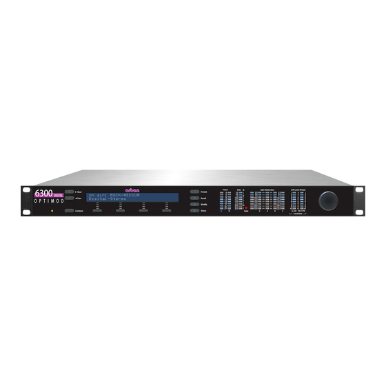
OPTIMOD 6300 DIGITAL OPERATION Section 3 Operation 6300 Front Panel Screen Display labels the four soft buttons and provides control-setting infor- mation. Screen Contrast button adjusts the optimum viewing angle of the screen dis- play. Four Soft buttons provide access to all 6300 functions and controls. The func-... - Page 120 OPERATION ORBAN MODEL 6300 Escape button provides an escape from current screen and returns user to the next higher-level screen. Repeatedly pressing Escape will always return you to the Idle screen, which is at the top level of the screen hierarchy.
-
Page 121: Introduction To Processing
In processing, there is a direct trade-off between loudness and distortion. You can improve one only at the expense of one or both of the other two. Thanks to Orban’s psychoacoustically optimized designs, this is less true of Orban processors than of any others. -
Page 122: Processing For Low Bit Rate Codecs
To exploit PreCode technology fully ( minimizing “phasey” and “underwater” arti- facts in low bit rate codecs), do not set up OPTIMOD 6300 for very bright sound (with large amounts of high frequency energy) because this is likely to exacerbate , and artifacts. -
Page 123: Speech/Music Detector
Speech that is not located in the center of the stereo sound field will always be de- tected as “music” because the detector always identifies stereo material as “music.” Optimod 6300 in Radio-Oriented Applications: From Bach to Rock The 6300 can be adjusted so that the output sounds: ... -
Page 124: Sound-For-Picture Applications: Controlling Dynamic Range
The challenge (which Optimod 6300 effectively meets) is to compress dy- namic range unobtrusively. OPTIMOD 6300 can be adjusted so that the output sounds as close as possible to the input at all times (using the 2-band Protection Limiter preset), or so that it sounds... - Page 125 L–R signal. Gating circuitry similar to that used in the “222- style” algorithm prevents over-enhancement and undesired enhancement on slightly unbalanced mono material. 2-band Gated AGC: The AGC is a 2-band device, using Orban’s patented “master / bass” band coupling. It has an additional important feature: target-zone gating. If...
- Page 126 622B), using a sophisticated, proprietary optimization program. The curves are matched to better than 0.15dB. This means that their sound is very close to the sound of an Orban analog parametric. They also use very high quality filter algo- rithms to ensure low noise and distortion.
-
Page 127: 2-Band Purist Processing
OPTIMOD 6300 DIGITAL OPERATION ness of the 6300's output. When subjective loudness would otherwise exceed a pre- set threshold, the Loudness Controller enhances the normal gain control produced by the processing with further gain reduction, preventing loudness from exceeding the threshold. The user can adjust this threshold from the Full modify screen of any 2-band preset. -
Page 128: Input/Output Delay
3-10 OPERATION ORBAN MODEL 6300 emphasis curve. The 6300’s 2-band phase-linear structure therefore keeps the musi- cal spectrum coherent and natural. Input/output Delay The input/output time delay is typically 25 ms—about three-quarters of an NTSC frame. To make intelligent decisions about how to process, the 6300 needs to look ahead at the next part of the program waveform. -
Page 129: Full Modify
3-11 OPTIMOD 6300 DIGITAL OPERATION optimized by Orban’s audio processing experts on the basis of years of experience designing audio processing and upon hundred of hours of listening tests. The L control has a different effect in the “radio” presets than it does in the “sound-for-picture”... -
Page 130: Advanced Modify
Modify levels. Gain Reduction Metering Unlike the metering on some processors, when any OPTIMOD 6300 gain reduction meter indicates full-scale (at its bottom), it means that its associated compressor has run out of gain reduction range, that the circuitry is being overloaded, and that... -
Page 131: To Create Or Save A User Preset
Because the various compressors have 25 dB of gain reduction range, the meter should never come close to 25 dB gain reduction if OPTIMOD 6300 has been set up for a sane amount of gain reduction under ordinary program conditions. -
Page 132: About The Processing Structures
3-14 OPERATION ORBAN MODEL 6300 You can save user presets from the 6300 PC Remote application. (See Using the 6300 PC Remote Control Software on page 3-57.) Please note that when you save presets from the PC Remote application, you save them in the 6300’s memory (as if you had saved them from the 6300’s... - Page 133 Both the 2-band and 5-band multiband compressors always operate in the back- ground. Switching between 2-band and 5-band therefore occurs with a seamless cross-fade. Unlike some older Orban processors, no DSP code gets reloaded and no audio mute occurs, although switching can sound obtrusive if the loudness normally produced by the 2-band and 5-band presets are very different.
-
Page 134: Factory Programming Presets
3-16 OPERATION ORBAN MODEL 6300 quency response as “allpass,” while adding 4 ms of delay to the processing. Most 2- band presets use the delay-line derived phase-linear crossover configuration. The 2-band structure contains a defeatable CBS Loudness Controller algorithm, which is mainly useful in sound-for-picture-oriented applications. The CBS Loudness Controller controls the loudness of most commercials well enough to eliminate viewer annoyance in sound-for-picture applications. -
Page 135: Protection And Agc Presets
3-17 OPTIMOD 6300 DIGITAL OPERATION eral types of audio systems (not just on your studio monitors). Then, if you wish, cus- tomize your sound using the information in the Protection Limiter, 2-band and 5- band sections that follow. Each factory preset has full L capability. - Page 136 3-18 OPERATION ORBAN MODEL 6300 Instead of adjusting L , you can adjust the F control (which INAL IMIT RIVE what L actually does). Do not set the F control below “0” INAL IMIT RIVE with this preset; doing so will compromise system headroom.
-
Page 137: Radio-Style Presets
The presets (Table 3-2 on page 3-20) have been named similarly to their radio coun- terparts in Orban’s OPTIMOD-FM 8400 and 8500. The basic audio texture of corre- sponding 6300 and 8500 presets (heard through the 8500’s digital radio output) is similar, although the 6300 will tend to have 1-2 dB more bass. - Page 138 3-20 OPERATION ORBAN MODEL 6300 of the analog and digital channels. In practice, this means that the cross- fade should be quite fast—perhaps 50 milliseconds. RADIO-STYLE PRESETS Preset Names Source Preset Normal Less-More CLASSICAL-2 BAND CLASSICAL-2 BAND CLASSICAL-2B SFTKN CLASSICAL-2B SFTKN...
- Page 139 3-21 OPTIMOD 6300 DIGITAL OPERATION Broadcasters using Orban’s Optimod-FM 8300, 8400, or 8500 will ordinar- ily use these processors’ HD FM digital outputs to feed the digital channel in an IBOC transmission. This eliminates any potential comb filtering be- cause both analog and digital outputs have identical amounts of phase rotation.
- Page 140 GREGG: GREGG and GREGG OPEN all use a 200 Hz band1/band2 crossover fre- quency to achieve a bass sound similar to the classic 5-band Gregg Labs FM proces- sors designed by Orban’s Vice President of New Product Development, Greg Ogonowski. Dynamically, these presets produce a slight increase in bass energy be- low 100 Hz and a decrease of bass energy centered at 160 Hz.
- Page 141 3-23 OPTIMOD 6300 DIGITAL OPERATION JAZZ: JAZZ is specifically tailored toward broadcasters that play mostly instrumental music, particularly classic jazz (Coltrane, Mingus, Monk, etc.). It is a quiet preset with a very clean, mellow high end to prevent stridency on saxes and other horns. It pre- serves much of the qualities of the original recordings, doing light re-equalization.
- Page 142 3-24 OPERATION ORBAN MODEL 6300 on-field sounds, so the preset does not pump this up as the NEWS-TALK preset would tend to do. ROCK: ROCK-DENSE, ROCK-MEDIUM, and ROCK-OPEN are appropriate for gen- eral rock and contemporary programming. They provide a bright high end and punchy low end (although not as exaggerated as the URBAN presets).
-
Page 143: Sound-For-Picture Presets
It sounds very similar to Orban’s analog OPTIMOD-TV (Model 8182A) when that unit is adjusted for “General” programming according to the instructions in its operating manual. -
Page 144: Equalizer Controls
3-26 OPERATION ORBAN MODEL 6300 These presets defeat the AGC and do all gain riding with the 2-band compressor, which is set for reverse exponential release. This release characteristic does not sig- nificantly increase the density of material whose level is well controlled while still performing fast correction of levels that are too low. - Page 145 3-27 OPTIMOD 6300 DIGITAL OPERATION also modify the Factory Preset (with Basic Modify, Full Modify, or Advanced Modify) before you create your User Preset. In general, you should be conservative when equalizing modern, well-recorded pro- gram material. This is particularly true with general-purpose video programming.
- Page 146 “mellowness” to the sound when boosting. When cutting, it can remove a “woody” or “boxy” sound. The equalizer, like the classic Orban analog parametrics such as the 622B, has con- stant “Q” curves. This means that the cut curves are narrower than the boost curves.
- Page 147 The curves in the 6300’s equalizer were created by a so-called “minimax” (“minimize the maximum error” or “equal-ripple”) IIR digital approximation to the curves pro- vided by the Orban 622B analog parametric equalizer. Therefore, unlike less sophis- ticated digital equalizers that use the “bilinear transformation” to generate EQ curves, the shapes of the 6300’s curves are not distorted at high frequencies.
- Page 148 The difference will never exceed the difference that would have other- wise occurred if the lowest frequency band were gated independently. If you are familiar with older Orban processors like the 8282, this is the maximum amount of boost that would have occurred if you had set their...
-
Page 149: Stereo Enhancer Controls
Stereo Enhancer Controls You can operate the stereo enhancer in one of two modes or “styles.” The first is called L–R E and emulates the Orban 222 analog stereo enhancer, while the XPAND second mode, called D , emulates a popular enhancer from another manufac- ELAY turer that adds a delayed version of the L–R signal to the original L–R to create ste-... -
Page 150: Agc Controls
3-32 OPERATION ORBAN MODEL 6300 In this case, the enhancer assumes that the program material is actually mono and thus suppresses enhancement to prevent the enhancement from exaggerating the undesired channel imbalance. The ratio of L–R / L+R of the enhanced signal tries to exceed the threshold set by the L-R / L+R Ratio Limit control. - Page 151 It is usually used to defeat the AGC when you want to create a preset with minimal processing (such as a CLASSICAL preset). The AGC is also ordinarily defeated if you are using a studio level controller (like Orban’s 8200ST). However, in this case it is better to defeat the AGC globally in System Setup.
- Page 152 AGC GATE (“AGC Gate Threshold”) control determines the lowest input level that will be recognized as program by OPTIMOD 6300; lower levels are considered to be noise or background sounds and cause the AGC or multiband compressor to gate, effectively freezing gain to prevent noise breathing.
- Page 153 3-35 OPTIMOD 6300 DIGITAL OPERATION AGC Idle Gain on page 3-36 explains how the AGC gate’s no-signal gain is deter- mined. The multiband silence gate causes the gain reduction in bands 2 and 3 of the multi- band compressor to move quickly to the average gain reduction occurring in those bands when the gate first turns on.
-
Page 154: Advanced Agc Controls
3-36 OPERATION ORBAN MODEL 6300 ting is not saved in User Presets, unlike the other controls in the Full Modify screens. The meter mode always reverts to M when the user leaves Full Modify. ASTER Advanced AGC Controls The following AGC controls are available only in the 6300 PC Remote software. - Page 155 3-37 OPTIMOD 6300 DIGITAL OPERATION control to zero. To make the idle gain 2 dB lower than the setting of the AGC D RIVE control, set the AGC I control to –2. AGC Bass Attack sets the attack time of the AGC bass compressor (below 200Hz).
-
Page 156: Distortion Control
Varied from 0.0 (Hard) to 10.0 (Soft) The distortion control adjustments are common to the 2-band and 5-band structures except as noted in the descriptions on the following pages. Bass Clip threshold controls Orban’s patented embedded bass clipper. Note that The S control overrides the B... - Page 157 3-39 OPTIMOD 6300 DIGITAL OPERATION the look-ahead limiter, causing audible intermodulation distortion between the bass and higher frequency program material. Some 6300 users feel that the bass clipper unnecessarily reduces bass punch at its factory settings. To accommodate these users, the threshold of the bass clipper is user-adjustable.
-
Page 158: The 2-Band Structure
3-40 OPERATION ORBAN MODEL 6300 You may find it illuminating to recall several Factory Presets, adjust L to several points in its range, and then open the Full Control screen to examine the trade-offs between the release time and F... -
Page 159: The 2-Band Structure's Full And Advanced Setup Controls
3-41 OPTIMOD 6300 DIGITAL OPERATION If you wish, you may adjust the Modify parameters to your own taste. Always start with L to get as close to your desired sound as possible. Then edit the Mod- ify parameters using the Basic, Intermediate or Advanced Modify screen, and save those edits to a User Preset. - Page 160 3-42 OPERATION ORBAN MODEL 6300 AGC set to O ) maintains a sense of dynamic range while still controlling levels ef- fectively. 2B REL (“2B Release”) control determines how fast the 2-band compressor releases (and therefore how quickly loudness increases) when the level of the program mate- rial decreases.
- Page 161 2B GATE (“2B Gate Threshold”) threshold control determines the lowest input level that will be recognized as program material by OPTIMOD 6300; lower levels are con- sidered to be noise or background sounds and will cause the AGC or 2-band com- pressor to gate, effectively freezing gain to prevent noise breathing.
- Page 162 3-44 OPERATION ORBAN MODEL 6300 The loudness controller is designed to follow 2-band or 5-band compression, which prevents it from being overdriven. It is only available in the M ULTIBAND processing chains. ULTIBAND IMITING The L control sets the subjective loudness level at which the...
-
Page 163: Advanced 2-Band Controls
3-45 OPTIMOD 6300 DIGITAL OPERATION PARENT PRESET and Less-More INDEX are read-only fields. The 6300’s front-panel LCD display does not show all of the parameters in a given User Preset; only the PC Remote software can display the Advanced Controls that set all the parameters. -
Page 164: Nee Atio
3-46 OPERATION ORBAN MODEL 6300 pression ratio to level off to :1. The maximum setting produces the softest knee. to 0 dB produces a classic hard knee curve with :1 compression ra- Setting the K tio regardless of the setting of the 2B M control. -
Page 165: The 5-Band Structure
3-47 OPTIMOD 6300 DIGITAL OPERATION mences slowly and then speeds up as it progresses. The 2B B control is only active when the 2B R control is set to REAKPOINT ELEASE HAPE INEAR Compression-induced audio density remains constant when the gain reduction is above the 2B B setting. -
Page 166: Putting The 5-Band Structure On The Air
3-48 OPERATION ORBAN MODEL 6300 The 5-band structure does not have a separate Loudness Controller because its 5- band compressor automatically re-equalizes the spectral balance of various pieces of program material in a way that tends to make their loudness more consistent. -
Page 167: The 5-Band Structure's Full And Advanced Setup Controls
3-49 OPTIMOD 6300 DIGITAL OPERATION The 5-band Structure’s Full and Advanced Setup Controls The tables below summarize the Multiband and Band Mix controls in the dynamics section. The AGC, Equalizer, Stereo Enhancer, and look-ahead limiter controls are common to both the 2-band and 5-band structures and are discussed in their own sections in Section 3. - Page 168 3-50 OPERATION ORBAN MODEL 6300 primary danger is that the excessive drive will cause noise to be increased excessively when the program material becomes quiet. You can minimize this effect by activat- ing the single-ended noise reduction and/or by carefully setting the M ULTIBAND control to freeze the gain when the input gets quiet.
- Page 169 3-51 OPTIMOD 6300 DIGITAL OPERATION MB Attack / Release / Threshold Full Name Advanced Name Range MB REL Multiband Release Slow, Slow2, Med, Med2, MFast, MFast2, Fast Speech Multiband Release Slow, Slow2, Med, Med2, MFast, MFast2, Fast B1 THR B1 Compression Threshold –16.00 …...
- Page 170 ORBAN MODEL 6300 MB GATE (“Multiband Gate Threshold”) control determines the lowest input level that will be recognized as program by OPTIMOD 6300; lower levels are considered to be noise or background sounds and cause the AGC or multiband compressor to gate, effectively freezing gain to prevent noise breathing.
- Page 171 3-53 OPTIMOD 6300 DIGITAL OPERATION Please note that it is impossible to design such a system to handle all program mate- rial without audible side effects. You will get best results if you set the MB D control of the noise reduction system to complement the program mate- XPANDER rial you are processing.
- Page 172 3-54 OPERATION ORBAN MODEL 6300 this point, every 2 dB increase in Band 4’s gain reduction will cause a 1 dB increase in Band 3’s gain reduction. B4>B5 CPL (“Band 4>5 Coupling”) controls the extent to which the gain of band 5 (6.2 kHz and above) is determined by and follows the gain of band 4.
-
Page 173: Advanced 5-Band Controls
3-55 OPTIMOD 6300 DIGITAL OPERATION Advanced 5-band Controls The following Advanced Multiband controls are available only from 6300 PC Remote software. B1-B5 Attack (Time); Speech B1-B5 Attack controls set the speed with which the gain reduction in each band responds to level changes at the input to a given band’s compressor for music and speech respectively, following the 6300’s automatic... -
Page 174: Test Modes
3-56 OPERATION ORBAN MODEL 6300 Note that the multiband gate only works appropriately when the K and R ATIO controls of all bands are set identically, which is typically the case in broadcast appli- cations. We recommend turning off the multiband gate if the individual K settings are unequal. -
Page 175: Using The 6300 Pc Remote Control Software
Before running 6300 PC Remote, you must have installed the appropriate Windows communications services on your computer. By default, the installer installs a short- cut to 6300PC.exe on your desktop and in your Start Menu under Orban\Optimod 6300. 6300 PC Remote can control only one 6300 at a time, but it can readily switch be- tween several 6300s. -
Page 176: To Set Up A New Connection
3-58 OPERATION ORBAN MODEL 6300 Before your PC can communicate with a given 6300, you must first set up a “connec- tion,” which is information that allows PC Remote to locate and communicate with the 6300. To set up a new connection: A) Launch 6300PC.exe. -
Page 177: To Modify A Control Setting
“Loading system files, please wait.” When run, the Orban PC Remote software installer makes copies of all 6300 fac- tory preset files on your local hard drive. The PC Remote software reads these files to speed up its initialization. -
Page 178: To Save A User Preset You Have Created
The encryption options prevent archived presets, system files, and auto- mation files from being restored if the user does not have the password used for the encryption. There is no “back door”— Orban cannot help you to decrypt a preset whose password is unknown. -
Page 179: To Restore Archived Presets, System Files, And Automation Files
If the preset, system file, or automation file was encrypted when it was originally saved, PC Remote will request the password under which it was encrypted. All User Presets are compatible with all 6300 software versions. If Orban adds new controls to a software version, the new software will assign a reasonable default value to any control missing in an old User Preset. -
Page 180: To Modify I / And S
3-62 OPERATION ORBAN MODEL 6300 b) Highlight all the user presets in the dialog window c) Click the R button. ESTORE E) To restore a system file: a) Set the F field to the System Setup file type (*.orb63setup). ILES b) Select the desired system file in the dialog box. -
Page 181: Navigation Using The Keyboard
There are a few extra things to know if you have multiple installations. If you install a new version of the Optimod 6300 PC Remote software on your PC, any Alias folders and backup subfolders created in an earlier software version still... - Page 182 Do not use an external file manager (like Windows Explorer) to do this. The old Alias folders need to be re-created under the Optimod 6300 PC Remote software you wish to use (so that the registry entries can be correctly updated). You can do this two different ways.
-
Page 183: Using The 6300 For Production And Mastering
3-65 OPTIMOD 6300 DIGITAL OPERATION them. New Alias folders will be created in the same location as the Optimod 6300 PC Remote executable. Important: The deletion process will automatically erase its associated folder, including the Backup directory. If you have anything in the... - Page 184 3-66 OPERATION ORBAN MODEL 6300 A program-adaptive high-frequency enhancer. This is a program-adaptive 6dB/octave shelving equalizer with a 4 kHz turnover frequency. It constantly monitors the ratio between high frequency and broadband energy and adjusts the amount of equalization in an attempt to make this ratio constant as the program material changes.
- Page 185 3-67 OPTIMOD 6300 DIGITAL OPERATION See Protection and AGC Presets on page 3-17 for a description of these presets. C) If you have started with one of the S presets, the AGC will already be . If you need a very large amount of compression for an application like...
- Page 186 3-68 OPERATION ORBAN MODEL 6300 The K control’s setting is the gain reduction in dB at which the com- pression ratio reaches :1. (See page 3-45 for a description of the R ATIO , and B controls.) REAKPOINT J) After you adjust the R...
- Page 187 3-69 OPTIMOD 6300 DIGITAL OPERATION allows attack transients to pass through the multiband compressor un- compressed, which can increase punch. There is a tradeoff between this control and the amount of gain reduction in the look-ahead limiter, which will have to eliminate attack transients exceeding the look-ahead limiter’s threshold.
- Page 188 3-70 OPERATION ORBAN MODEL 6300 At 44.1 kHz, the output samples are not exactly the same ones that the look-ahead limiter controlled at the internal 48 kHz sample rate, so slight overshoot can occur. If your mastered audio is intended for transmission via a lossy codec like AAC, MP3 or WMA, be aware that the codec’s decoder may overshoot...
-
Page 189: Section 4 Maintenance
6300 is at fault. The troubleshooting information in Section 5 will help you determine if the problem is with OPTIMOD 6300 or is somewhere else in the station's equip- ment. -
Page 190: Subassembly Removal And Replacement
MAINTENANCE ORBAN MODEL 6300 Subassembly Removal and Replacement See page 6-21 for the Circuit Board Locator and Basic Interconnections diagram. 1. Removing the Top Cover: To access any internal board (including the display assembly), you must remove the top cover. - Page 191 EMI. If the power supply fails, please contact Orban Customer Service (custserv@orban.com) to obtain an exact replacement. A) Verify that the 6300 is disconnected from the AC line.
- Page 192 MAINTENANCE ORBAN MODEL 6300 D) Remove the plug that connects the power supply to the AC line socket. E) Unplug the cable connecting the output of the power supply to the I/O+DSP board. F) Using a hex nutdriver, remove the threaded standoff that supports the power supply’s insulating cover.
- Page 193 OPTIMOD 6300 DIGITAL MAINTENANCE d) Evenly tighten all eight screws to reattach the board assembly to the panel. D) Place the two side brackets over the captive screws located on each side of the front panel. Be sure that the large side of each bracket is oriented toward the rack-screw cutouts in the panel.
-
Page 194: Field Audit Of Performance
MAINTENANCE ORBAN MODEL 6300 Field Audit of Performance Required Equipment: Ultra-low distortion sine-wave oscillator / THD analyzer / audio voltmeter With verified residual distortion below 0.01%. Audio Precision System One, or similar high-performance system. The NAB Broadcast and Audio System Test CD is an excellent source of test signals when used with a high-quality CD player. - Page 195 OPTIMOD 6300 DIGITAL MAINTENANCE Note: All analog output measurements are taken with a 620 ±5% resistor tied be- tween pin 2 and 3 of the XLR connector. 1. Prepare the unit. A) Use the front panel controls to set the 6300's software controls to their de- fault settings, as follows.
- Page 196 The power supply is a module. In case of any power supply failure, the entire supply must be replaced by an exact replacement (available from Orban Service). Attempts to repair the supply on a component level and/or to replace the supply with a non-approved supply may compromise your Optimod’s compliance with...
- Page 197 OPTIMOD 6300 DIGITAL MAINTENANCE H) Using VR201, repeat steps (C) through (G) for the Right Analog Output. 4. Check frequency response of Analog I/O. A) Verify 6300 software controls are set to their default settings. [Refer to step (1.A) on page 4-7.] B) Be sure you are still in B mode [see step (3.F)].
-
Page 198: C) Navigate To S
4-10 MAINTENANCE ORBAN MODEL 6300 G) Repeat the above measurements for the right channel. Connect the oscillator to the right analog input and the distortion analyzer to the right analog out- put. H) Disconnect the oscillator and THD analyzer from the 6300. - Page 199 PC through a null modem cable. See Networking and Remote Con- trol starting on page 2-36 (in particular, step 4 on page 2-38). 10. Return OPTIMOD 6300 to service. A) Remove the 620 resistors connected across the outputs.
-
Page 201: Section 5 Troubleshooting
OPTIMOD 6300 DIGITAL TROUBLESHOOTING Section 5 Troubleshooting Problems and Potential Solutions Always verify that the problem is not the source material being fed to the 6300, or in other parts of the system. RFI, Hum, Clicks, or Buzzes For good RFI resistance, always use balanced inputs and outputs. -
Page 202: Audible Noise
TROUBLESHOOTING ORBAN MODEL 6300 Verify that the source material at the 6300's audio inputs is clean. Heavy processing can exaggerate even slightly distorted material, pushing it over the edge into unac- ceptability. The subjective adjustments available to the user have enough range to cause audi- ble distortion at their extreme settings. -
Page 203: Gain Pumping When High Frequency Energy Is Present
STL may only be 70-75 dB. In this case, it is wise to use an Orban Studio AGC to perform the AGC function prior to the STL transmitter and to control the STL's peak modulation. This will optimize the signal-to-noise ratio of the entire transmission system. -
Page 204: Excessive Sibilance ("Ess" Sounds)
TROUBLESHOOTING ORBAN MODEL 6300 Excessive Sibilance (“ess” sounds) If “ess” sounds in speech (particularly with women’s voices) seem too pronounced, set the B5 T control more negative. (Note that this will also reduce the HRESHOLD brightness of music, so a careful compromise is usually required.) -
Page 205: Aes Channel Status Bits Will Not Set The 6300 To Stereo Or Dual-Mono Mode
OPTIMOD 6300 DIGITAL TROUBLESHOOTING AES Channel Status Bits Will Not Set the 6300 to Stereo or Dual-Mono Mode Be sure that the equipment driving the 6300 is set in AES3 or AES/EBU mode. (SPDIF will not work.) Similarly, you must set the 6300’s digital output mode (via the DO1 FORMAT or DO2 FORMAT control) to AES in order to send AES channel status bits to downstream equipment. -
Page 206: Troubleshooting Connections
TROUBLESHOOTING ORBAN MODEL 6300 Passcode Format: The passcode is case-sensitive. When entering it into Win- dows’ Dial-up Connection dialog box, it must be typed exactly as it was origi- nally entered into the Security screen. Troubleshooting Connections If you get an error message such as “the specified port is not connected” or “There is no answer”…... -
Page 207: Os-Specific Troubleshooting Advice
A) Click “Start / Programs / Accessories / Communications / Network and Dialup Connections” to bring up the Network Connections screen. B) In the “Network Connections” window, right-click “Optimod 6300 - Direct” and choose “Properties.” C) The “Properties” window opens for “Optimod 6300 - Direct D) Click the “Networking”... -
Page 208: Troubleshooting Windows 2000 Modem Connect
TROUBLESHOOTING ORBAN MODEL 6300 K) In the “Advanced TCP/IP Settings” select the “General” Tab; make sure that no check boxes are checked. L) In the “Advanced TCP/IP Settings” select the “DNS” Tab. M) In the “Advanced TCP/IP Settings” select the “WINS” Tab. -
Page 209: Troubleshooting Windows Xp Direct Connect
A) Click “Start / Programs / Accessories / Communications / Network and Dialup Connections” to bring up the Network Connections screen. B) In the “Network Connections” window, right-click “Optimod 6300 - Modem” and choose “Properties.” C) The “Properties” window opens for “Optimod 6300 – Modem.”... -
Page 210: Troubleshooting Windows Xp Modem Connect
L) Click “OK” to dismiss the “Advanced TCP/IP Settings” window. M) On the “Properties” window for “Optimod 6300 – Modem” click the “Ad- vanced” tab. N) Click “OK” to dismiss the window whose name is your new connection. -
Page 211: Troubleshooting Ic Opamps
5-11 OPTIMOD 6300 DIGITAL TROUBLESHOOTING C) Click the “Networking” tab. D) Set “Type of dial-up server I am calling” to “PPP: Windows 95 / 98 / NT4 / 2000, Internet” E) Select the “Settings” button. Make sure all PPP settings are unchecked, and then click “OK.”... -
Page 212: Technical Support
Returned units will be returned C.O.D. if the unit is not under warranty. Orban will pay return shipping if the unit is still under warranty. In all cases, the customer pays transportation charges to the factory (which are usually quite nominal). - Page 213 5-13 OPTIMOD 6300 DIGITAL TROUBLESHOOTING Close the carton without sealing it and shake it vigorously. If you can hear or feel the unit move, use more packing. Seal the carton with 3-inch (8 cm) reinforced fi- berglass or polyester sealing tape, top and bottom in an “H” pattern. Narrower or parcel-post type tapes will not withstand the stresses applied to commercial ship- ments.
-
Page 215: Section 6 Technical Data
OPTIMOD 6300 DIGITAL TECHNICAL DATA Section 6 Technical Data Specifications It is impossible to characterize the listening quality of even the simplest limiter or compressor based on specifications, because such specifications cannot adequately describe the crucial dynamic processes that occur under program conditions. There- fore, the only way to evaluate the sound of an audio processor meaningfully is by subjective listening tests. -
Page 216: Installation
TECHNICAL DATA ORBAN MODEL 6300 Delay: The minimum available input/output delay is approximately 20 ms with look-ahead limiting active and 6 ms with look-ahead limiting bypassed. This can be padded to ex- actly one frame of 24, 25, 29.97, or 30 frames / second video up to a maximum delay of 50 ms. - Page 217 OPTIMOD 6300 DIGITAL TECHNICAL DATA User Bits: Unit can pass AES3 User Bits from its AES input to AES Output #1. Sampling Rate: 32, 44.1, 48, 88.2, or 96 kHz, automatically selected. Connector: XLR-type, female, EMI-suppressed. Pin 1 chassis ground, pins 2 and 3 trans- former balanced and floating, 110...
-
Page 218: Circuit Description
RFI / EMI: Tested according to Cenelec procedures. FCC Part 15 Class A device. Shipping Weight: 10 lbs / 4.6 kg Warranty Two Years, Parts and Service: Subject to the limitations set forth in Orban's Standard Warranty Agreement. Because engineering improvements are ongoing, specifications are subject to change with- out notice. -
Page 219: Overview
The flash memory holds the operating system, the Orban executable program, and all preset files, both factory and user. It also contains a write-protected “boot seg- ment”... -
Page 220: User Control Interface And Lcd Display Circuits
Located on control board A remote interface connector and circuitry implements remote control of certain operating modes; Optimod 6300 has eight remote contact closure inputs. A valid remote signal is a momentary pulse of current flowing through remote signal pins. Current must flow consistently for 50msec for the signal to be inter- preted as valid. -
Page 221: Input Circuits
OPTIMOD 6300 DIGITAL TECHNICAL DATA Component-Level Description: S1-S11 are the front panel pushbutton switches. CR11-CR15 are the front panel LED control status indicators. The control microprocessor communicates with these components through the General Purpose bus, which is buffered via IC3. - Page 222 TECHNICAL DATA ORBAN MODEL 6300 Note that the small RFI “tee” filter assemblies connected to the input and output connectors are socketed and user-replaceable. Component-Level Description: The left channel balanced audio input signal is applied to the filter / load net- work made up of L100-103 and associated resistors and capacitors.
-
Page 223: Output Circuits
OPTIMOD 6300 DIGITAL TECHNICAL DATA Output Circuits This circuitry interfaces the DSP to the analog and digital audio outputs. The digital audio from the DSP is transmitted to the digital-to-analog converter (D/A) and out- put sample rate converter (SRC). The digital-to-analog (D/A) converter converts the digital audio words generated by the DSP to analog audio. -
Page 224: Dsp Circuit
During system initialization, the SC520 queries the DSP hardware about its opera- tional status and will display an error message on-screen if the DSP fails to initialize normally. Please note any such messages and be ready to report them to Orban Cus- tomer Service. -
Page 225: Abbreviations
Because of safety and EMI suppression requirements in the power supply, there are no user-serviceable parts in it. In case of failure, replace the entire supply with an Orban-supplied replacement (Orban part number 29270.000.01.1), which ensures that your Optimod will continue to meet all regulatory requirements for safety and emissions. - Page 226 6-12 TECHNICAL DATA ORBAN MODEL 6300 G / R gain reduction HD Radio See IBOC high-frequency high-pass IBOC “In-Band On-Channel”—a form of digital radio commercialized by iBiquity Corporation where the digital carriers use a form of COFDM modulation and share the frequency alloca- tion of the analog carriers.
-
Page 227: Parts List
Consult the factory if the listing of a part includes the note “selected” or “realignment required.” Orban normally maintains an inventory of tested, exact replacement parts that can be supplied quickly at nominal cost. Standardized spare parts kits are also available. - Page 228 6-14 TECHNICAL DATA ORBAN MODEL 6300 Control Board PART # DESCRIPTION COMPONENT IDENTIFIER 20130.475.01 RESISTOR, 4.75K, 0805 (R36, NO, STUFF), R205, R207, R209, R211, R213, R215, R217 20130.562.01 RESISTOR, 1/8W, 1%, 5.62K, 0805 20131.100.01 RESISTOR, 10K, 0805 R1, R2, R9, R33, R37, R38, R39, 20131.113.01...
-
Page 229: Combined Input/Output And Dsp (I/O+Dsp) Board
6-15 OPTIMOD 6300 DIGITAL TECHNICAL DATA Control Board PART # DESCRIPTION COMPONENT IDENTIFIER 24972.520.01 IC MICROPROCESSOR ELANSC520 BGA388 24979.000.01 IC, BAT54C-7 CR11, CR12 24983.000.01 IC, 7064STC100-10 25008.000.01 IC, PS2506-4 * U17, U19 27017.009.01 CONNECTOR, RT AGL, PC MNT, 9P 27017.025.01 CONNECTOR, RT AGL, PC MNT, 25P 27147.124.01... - Page 230 6-16 TECHNICAL DATA ORBAN MODEL 6300 I/O+DSP BOARD PART # DESCRIPTION COMONENT IDENTIFIER 20128.022.01 RESISTOR 22 Ω 1% 0805 R806, R807, R808, R809, R810, R811, R813, R820 20128.075.01 RESISTOR, 75Ω, 1%, 0805 R158, R303 20129.100.01 RESISTOR, 100 Ω, 0805 R257, R258, R259, R260 20129.110.01...
- Page 231 6-17 OPTIMOD 6300 DIGITAL TECHNICAL DATA I/O+DSP BOARD PART # DESCRIPTION COMONENT IDENTIFIER C1012, C1013 21140.000.01 CAPACITOR, NPO, 470PF, 1%, 0805 C217, C218, C219, C220 21141.000.01 CAPACITOR, NPO, 1000PF, 1%, 0805 C236, C237, C238, C239, C305 21142.000.01 CAPACITOR, NPO, 100PF, 1%, 0805 C989 21143.000.01...
-
Page 232: Display Board (Front)
6-18 TECHNICAL DATA ORBAN MODEL 6300 I/O+DSP BOARD PART # DESCRIPTION COMONENT IDENTIFIER 27421.010.01 CONNECTOR, HEADER, DBL RW, 23", J800, J903 2 X 5 27426.003.01 CONNECTOR, HEADER, 3 PIN, SINGLE J801 27451.009.01 HEADER STR DBLRW 60P PCMT J701 27630.001.01 JUMPER, PC MNT, TEST POINT... -
Page 233: Display Board (Back)
6-19 OPTIMOD 6300 DIGITAL TECHNICAL DATA Display Board (Back) PART # DESCRIPTION COMPONENT IDENTIFIER 42007.100 FLAT CABLE 26P 10" JP203 15065.355.01 LED-MNT-1 POS-0.355 FOR, CR1 USE 2 20122.110.01 RESISTOR, TF, 1/8W, 1%, 110 ohm R17, R18, R19, R20, R21, R22, R23, 20124.100.01... -
Page 234: Drawings
6-20 TECHNICAL DATA ORBAN MODEL 6300 Function Description Drawing Page Chassis Circuit Board Locator and Basic In- Top view 6-21 terconnections (not to scale) Control board Control microprocessor. Services Parts Locator 6-22 front panel, serial port, Ethernet, Drawing and DSP+I/O board. - Page 235 6-21 OPTIMOD 6300 DIGITAL TECHNICAL DATA WARNING: INPUT/OUTPUT PARTS SECTION UNDER SHIELD ARE EXPOSED TO AC LINE CONTROL INPUT/OUTPUT+DSP BOARD BOARD POWER SUPPLY DSP SECTION DISPLAY ASSEMBLY...
- Page 236 6-22 TECHNICAL DATA ORBAN MODEL 6300 CONTROL BOARD PARTS LOCATOR...
- Page 237 6-23 OPTIMOD 6300 DIGITAL TECHNICAL DATA C44 10UF +3.3V 10.0K 0.1UF SYSTEM_RESET-N (SHT 5) U5 MIC8115TU +3.3V U1B SC520 MR-n PIO14/GPIRQ9 RESET-n PWRGOOD PIO14/GPIRQ9 AC22 GP_RESET GPRESET PRGRESET PRGRESET MCP120-475I/TT 10.0K (SHT 5) 7x 4.75K DACK1-N PIO11/GPDACK1 AF10 DREQ1 PIO7/GPDRQ1...
- Page 238 6-24 TECHNICAL DATA ORBAN MODEL 6300 MD[0..31] MA[0..12] U2A MT48LC16 U3A MT48LC16 U1A SC520 MA12 MA12 MD15 MA12 MD31 MA12 DQ15 DQ15 MA11 MA11 MD14 MA11 MD30 MA11 DQ14 DQ14 MD31 MA10 +3.3V MA10 MD13 MA10 MD29 MD31 MA10 A10/AP...
- Page 239 6-25 OPTIMOD 6300 DIGITAL TECHNICAL DATA +3.3V PCI_AD[0..31] RNET4.7K +3.3V U1C SC520 U10A DP83816AVNG +3.3V PCI_AD31 PCI_AD31 REQ4 AD31 AD31 PCI_AD30 PCI_AD30 REQ3 AD30 AD30 PCI_AD29 PCI_AD29 REQ2 AD29 AD29 PCI_AD28 PCI_AD28 REQ1 AD28 AD28 PCI_AD27 PCI_AD27 AD27 AD27 PCI_AD26...
- Page 240 6-26 TECHNICAL DATA ORBAN MODEL 6300 PWRGOOD +3.3V (SHT2) +3.3V 100K 100K 100K 0 OHM U1D SC520 (NO-STUFF) 4.75K AF25 AC13 TRIG/TRACE TRIG/TRACE AF23 AD24 BR/TC BR/TC AE21 JTAG_TMS JTAG_TMS AE25 AF21 JTAG_TDI JTAG_TDI AE24 AD21 JTAG_TCK JTAG_TCK AD26 PIO31/RING2-N...
- Page 241 6-27 OPTIMOD 6300 DIGITAL TECHNICAL DATA +3.3V U10B DP83816AVNG +3.3V +3.3V (NO-STUFF) +3.3V U2B MT48LC16 U3B MT48LC16 U4B E28F128 C201 RESERVED 1.0UF RESERVED RESERVED +3.3V VCCQ VSSQ VDDQ VSSQ VDDQ VSSQ VDDQ VSSQ VDDQ VSSQ VDDQ VSSQ VDDQ VSSQ VDDQ...
- Page 242 6-28 TECHNICAL DATA ORBAN MODEL 6300 I/O+DSP BOARD PARTS LOCATOR...
- Page 243 6-29 OPTIMOD 6300 DIGITAL TECHNICAL DATA LEFT ANALOG INPUT +15V R130 R131 J100 FEMALE L100 IC100A 3.65K 1.50K FILTER 0.1% R100 L101 R101 OPA2134PA C108 E101 1200µH ????? C101 47PF 1000PF C100 47PF 5%,100V -15V 5%,100V R132 C132 R159 IC104B...
- Page 244 6-30 TECHNICAL DATA ORBAN MODEL 6300 LEFT ANALOG OUTPUT (6300) ANALOG OUTPUT 1 (9300) L204 +5VA J201 L200 MALE C201 FILTER 1.0µF R253 R257 C232 1.0µF L208 ????? 1000PF Servo R261 C203 C236 C240 f-3dB = 0.10Hz 0.1µF +15V C233 0.1µF...
- Page 245 6-31 OPTIMOD 6300 DIGITAL TECHNICAL DATA E313 PICSDI (SHT8) AES/EBU AESINCS-N (SHT8) DIGITAL INPUT R301 49.9K AESINLRCK (SHT5) J300 L300 FEMALE AESINSCLK (SHT5) C300 PICSCK (SHT8) IC300 IC302 T300 R300 PICSDO (SHT8) FERRITE SC937-02 SDA/CDOUT SCL/CCLK ????? 0.1µF 110OHM MMODE_2...
- Page 246 6-32 TECHNICAL DATA ORBAN MODEL 6300 IC400 IC403 AES/EBU DIGITAL PICSDI PICSCK OUTPUT 1 IC410A MMODE_2 (SHT8) SDA/CDOUT SCL/CCLK (SHT8) IC410B IC409A J400 L400 MCLK_C AESOUT1CS-N PICSDO (SHT9) MCLK_IN MMODE_1 (SHT8) AD0/CS AD1/CDIN (SHT8) MALE R400 T400 74ACT32 MCLK_OUT MMODE_0...
- Page 247 6-33 OPTIMOD 6300 DIGITAL TECHNICAL DATA E34 E35 IC501A IC502A IC503A IC504A E36 E37 DSP56367-150 DSP56367-150 DSP56367-150 DSP56367-150 SD03 SD32 (SHT9) SDI0 SDO0 SDI0 SDO0 SDI0 SDO0 SDI0 SDO0 (SHT9) SD04 SD33 (SHT9) SDI1 SDO1 SDI1 SDO1 SDI1 SDO1 SDI1...
- Page 248 6-34 TECHNICAL DATA ORBAN MODEL 6300 IC501C IC502C IC503C IC504C DSP56367-150 DSP56367-150 DSP56367-150 DSP56367-150 AA0/RAS0 AA0/RAS0 AA0/RAS0 AA0/RAS0 AA1/RAS1 AA1/RAS1 AA1/RAS1 AA1/RAS1 AA2/RAS2 AA2/RAS2 AA2/RAS2 AA2/RAS2 SSI_DO (SHT8) SSI_DI (SHT8) SSI_CLK (SHT8) DSPEN0-N DSPEN1-N DSPEN2-N DSPEN3-N (SHT8) (SHT8) (SHT8) (SHT8)
- Page 249 6-35 OPTIMOD 6300 DIGITAL TECHNICAL DATA IC702 74LVX4245 +3.3V IC703 PIC16C67-20L C700 IC700 0.1µF E712 ISA_D[0..7] E713 E714 E703 (SHT4) RD0/PSP0 RC0/T1OSO/T1CKI E704 IORD-N E715 B to A ADRST-N RD1/PSP1 RC1/T1OSI/CCP2 E705 ISA_D0 DSP_BUSEN-N (SHT9) DARST-N RD2/PSP2 RC2/CCP1 ISA_D1 (SHT9)
- Page 250 6-36 TECHNICAL DATA ORBAN MODEL 6300 +3.3V +3.3V +3.3V JTAG PORT +3.3V IC807G R816 R817 R818 IC800 74ACT04D 100.0K 100.0K 100.0K C809 +3.3V VCCINT 0.1µF J800 VCCINT VCCIO VCCIO VCCIO VCCIO VCCIO HDR 5X2 VCCIO UNSHRD +3.3V IC804A IC807E C804...
- Page 251 6-37 OPTIMOD 6300 DIGITAL TECHNICAL DATA FROM POW ER SUPPLY TO CONTROL COMBO PCA TP902 (NO-STUFF) TP-DUAL J900 J901 C946 10µF C1003 C1004 C947 C948 C949 C950 C951 C952 C953 C954 C955 C956 C957 C958 C959 + C995 C996 0.1µF 0.1µF...
- Page 252 6-38 TECHNICAL DATA ORBAN MODEL 6300 FRONT VIEW REAR VIEW FRONT PANEL PARTS LOCATOR DIAGRAM...
- Page 253 6-39 OPTIMOD 6300 DIGITAL TECHNICAL DATA CR1A CR1B CR1C CR1D CR1E CR1F CR1G CR1H CR1I CR1J CR2A CR2B CR2C CR2D CR2E CR2F CR2G CR2H CR2I CR2J CR3A CR3B CR3C CR3D CR3E CR3F CR3G CR3H CR3I CR3J CR4A CR4B GNDF T O GND PLA NE ON LY...
- Page 254 6-40 TECHNICAL DATA ORBAN MODEL 6300 RP 2 IC7C IC7F 74HC14A 74HC14A IC7D RES_NET 74HC14A D[0..7] D[0..7] 100 OHM 74AC574 74FCT574 IC7E DI SROW A DI SCOL B FY10 FY11 74HC14A FY12 FY13 SPARES 47PF FY14 FY15 8x2 POSTS 8x2 POSTS...
- Page 255 6-41 OPTIMOD 6300 DIGITAL TECHNICAL DATA...
Need help?
Do you have a question about the OPTIMOD 6300 and is the answer not in the manual?
Questions and answers