
Related Manuals for Nikon ECLIPSE MA200


Summary of Contents for Nikon ECLIPSE MA200
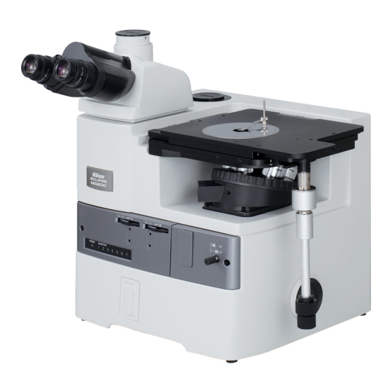
- Page 1 M498E 08.10.NF.1 (2/4) Inverted Metallurgical Microscope ECLIPSE MA200 Instructions...
-
Page 3: Introduction
• The contents of this manual are subject to change without notice. • Although every effort has been made to ensure the accuracy of this manual, errors or inconsistencies may remain. If you note any points that are unclear or incorrect, please contact your nearest Nikon representative. -
Page 4: Safety Precautions
Safety Precautions To ensure correct and safe operation, read this manual before using the product. Warning and Caution Symbols Used in This Manual Although this product is designed and manufactured to be completely safe during use, incorrect usage or failure to follow the safety instructions provided may cause personal injury or property damage. To ensure correct usage, read this manual carefully before using the product. -
Page 5: Warning
Nikon 12V 50W Precentered Lamphouse (model name: LV-LH50PC) • Lamp Nikon 12V 50W longlife halogen lamp (model name: LV-HL50W) or 12V 50W shortlife halogen lamp from other manufacturers (model name: OSRAM HLX 64610, OSRAM HLX 64611, or PHILIPS 7027). For the diascopic illumination •... - Page 6 To perform the epi-fl microscopy with this product, the brightness of the specified light source may be less than the desired brightness. In this case, connect an external light source that has a mercury lamp, Nikon INTENSILIGHT HG Precentered Fiber Illuminator (model: C-HGFI manual type, or C-HGFIE motorized type) to MA200 to be used.
-
Page 7: Caution
Then, wipe off the water with a piece of dry cloth. If water enters a component, immediately suspend use of this product, disconnect the power cord from the outlet, and contact your nearest Nikon representative. Weak electromagnetic waves The product emits weak electromagnetic waves. - Page 8 Safety Precautions • Do not hold the focus knobs, eyepiece tube, lamphouse, stage, and so on, when carrying the microscope. They may come off and may cause serious injury or malfunction. • Be careful not to pinch your hands or fingers during transportation. Cautions on assembling the microscope •...
-
Page 9: Table Of Contents
Contents Introduction ..................................1 Safety Precautions................................2 Warning and Caution Symbols Used in This Manual ....................2 Meaning of Symbols Used on the Product ......................... 2 WARNING ................................3 CAUTION ................................5 Part Name and Function ............................10 Microscopy ................................14 Bright-field Microscopy under the Episcopic Illumination ................ - Page 10 Contents 3.13.2 Adjusting the polarizer direction ....................44 3.14 Using the λ Plate (MA2-λP)........................... 45 3.14.1 Inserting/removing the λ plate ....................... 45 3.15 Using the DIC Slider (L-DIHC/L-DIC)......................46 3.15.1 Inserting/removing the DIC prism from the optical path ..............46 3.15.2 Setting the DIC prism ........................
- Page 11 Contents Network Connection............................73 4.3.1 Unit system capable of establishing network................. 73 4.3.2 Viewing user control options and status displays on a PC or the DS-L2 ........74 4.3.3 Registering information on the objective ..................76 4.3.4 Procedure for turning on the power switch ..................76 The LV-LH50PC Lamphouse and the Lamp....................
-
Page 12: Part Name And Function
Part Name and Function Eyepiece Sample holder 10X, 12.5X, 15X (and 10X The stage is equipped with the standard are equipped with the sample holder (with a sample clip). (Refer to mask eyepiece.) 3.8.) Eyepiece tube (Figure illustrates Sample clip the MA2-TI3.) Binocular eyepiece may also be used. - Page 13 Chapter 1 Part Name and Function POWER LED Displays ON/OFF for the power switch or the light-status for the illumination lamp. Additionally, the display status remains the same when an external PC is in use. Power switch OFF: LED turns off Power switch ON;...
- Page 14 Chapter 1 Part Name and Function Optical path changeover Supporting Pillar for Dia-Illuminator Eyepiece tube clamp screw lever (eyepiece tube/back 100W/Supporting Arm for DS-L2 attaching part port) (Refer to 3.4.) (Refer to 3.23 and 3.24.) Optical path changeover lever Press: Eyepiece tube/back Attach the supporting pillar for (vertical tube/binocular tube) port =100/0...
- Page 15 About product parts names in this manual The right column of the table below shows the product parts names described in this manual. Package names Parts names in the ECLIPSE MA200 Instructions MA2-TI3 Trinocular Eyepiece Tube ESD (erect image) MA2-TI3 Trinocular Eyepiece Tube...
-
Page 16: Microscopy
Microscopy This chapter describes the procedure of each microscopy. See Table 2.1 for the items required for each microscopy. • Refer to “4. Assembly,” when the product has not been assembled yet. • For detailed information about operations of parts of the product, refer to “3. Operation Details.” •... - Page 17 Chapter 2 Microscopy Table 2.1 Items required for the microscopy Microscopy Page Illuminator Revolving nosepiece Objective Other items required • For EPI objectives with 5 BF microscopy p.16 to p.18 5 revo., 6 revo., under the epi 7 revo. revo., LU nosepiece illumination adapter M32-25 required ⎯...
-
Page 18: Bright-Field Microscopy Under The Episcopic Illumination
Chapter 2 Microscopy Bright-field Microscopy under the Episcopic Illumination Turn on the power to light up the episcopic illumination lamp. 1 Turn on the power switch. (See 3.1.1.) The power LED on the front is lit. 2 Be sure that the Internal/External brightness control changeover switch is set to OFF “internal mode.”... - Page 19 Chapter 2 Microscopy Set the microscope for the bright-field microscopy under the episcopic illumination. If the current unit is the one shown in the column at the right edge under “Other items required” in Table 2.1, pull out each item from the optical path. 1 Push in the optical path changeover lever for the eyepiece tube and select 100% for the binocular eyepiece.
- Page 20 Chapter 2 Microscopy Set the desired magnification and observe the sample. 1 Turn the revolving nosepiece to place the objective of a desired magnification into the optical path. (See 3.9.2.) 2 Turn the coarse/fine focus knobs and refocus on the sample. (See 3.7.) 3 Turn the brightness control dial to adjust the brightness of the episcopic illumination.
-
Page 21: Dark-Field Microscopy Under The Episcopic Illumination
Chapter 2 Microscopy Dark-field Microscopy under the Episcopic Illumination Attach the items required for the dark-field microscopy under the episcopic illumination to the microscope. (See Table 2.1.) Focus on the sample with the bright-field microscopy under the episcopic illumination. (See Pages 16 and 17.) Set the microscope for the dark-field microscopy under the episcopic illumination. -
Page 22: Polarization Microscopy Under The Episcopic Illumination (Simplified/Sensitive Color)
Chapter 2 Microscopy Polarization Microscopy under the Episcopic Illumination (simplified/sensitive color) Attach the items required for the polarization microscopy under the episcopic illumination to the microscope. (See Table 2.1.) Focus on the sample with the bright-field microscopy under the episcopic illumination. (See Pages 16 to 17.) Set the microscope for the polarization microscopy under the episcopic illumination. -
Page 23: Differential Interference Contrast Microscopy Under The Episcopic Illumination
Chapter 2 Microscopy Differential Interference Contrast Microscopy under the Episcopic Illumination Attach the items required for the differential interference contrast (DIC) microscopy under the episcopic illumination to the microscope. (See Table 2.1.) Focus on the sample with the bright-field microscopy under the episcopic illumination. (See Pages 16 and 17.) Set the microscope for the DIC microscopy under the episcopic illumination. -
Page 24: Epi-Fl Microscopy
Chapter 2 Microscopy Return to the bright-field microscopy under the episcopic illumination. 1 Pull the polarizer/analyzer unit to the first stop-click position and remove the polarizer/analyzer from the optical path. (See 3.13.1.) 2 Both the λplate and the polarizer/analyzer unit are removed from the optical path. - Page 25 Chapter 2 Microscopy Return to the bright-field or dark-field microscopy under the episcopic illumination. 1 Turn the BD field changeover lever to the “BF (bright-field)” or “DF (dark-field)” position. (See 3.3.) 2 Turn the brightness control dial to adjust the brightness.
-
Page 26: Bright-Field Microscopy Under The Diascopic Illumination
Chapter 2 Microscopy Bright-field Microscopy under the Diascopic Illumination Attach the items required for the bright-field microscopy under the diascopic illumination. (See Table 2.1.) Turn on the power to light up the diascopic illumination lamp. (See 3.23.1.) 1 Set the brightness control dial to OFF on the MA200 main body. - Page 27 Chapter 2 Microscopy Set the microscope for the bright-field microscopy under the diascopic illumination. When the “Other items required” (See the column at the right edge of Table 2.1.) is used for the episcopic illumination, remove each attachment from the optical path in advance. 1 Push in the optical path changeover lever for the eyepiece tube and select 100% for the binocular eyepiece.
- Page 28 Chapter 2 Microscopy Place the sample onto the stage to adjust the focus. 1 Use the sample holder according to the selected sample. Place the sample onto the stage and move the stage using the stage movement knob for the X/Y direction so that the observation position comes to the center of the view-field.
- Page 29 Chapter 2 Microscopy Center the condenser. (See 3.23.2.) 1 Be sure that the objective is set to the 10X objective. If not, turn the revolving nosepiece to place the 10X objective into optical path. 2 Stop down the field diaphragm by turning the field 7-2, 6 diaphragm dial on the supporting pillar for dia-Illuminator until the field diaphragm image...
-
Page 30: Polarization Microscopy Under The Diascopic Illumination (Simplified/Sensitive Color)
Chapter 2 Microscopy Polarization Microscopy under the Diascopic Illumination (simplified/sensitive color) Attach the items required for the polarization microscopy under the diascopic illumination to the microscope. (See Table 2.1.) Focus on the sample with the bright-field microscopy under the diascopic illumination and center the condenser. -
Page 31: Operation Details
Operation Details Power ON/OFF 3.1.1 Power of the microscope The power switch for the product is located beside the AC inlet on the rear of the microscope. To turn on the product, set the power switch to the “|” side. To turn off the microscope, set the power switch to the “... -
Page 32: Illumination
Chapter 3 Operation Details Illumination 3.2.1 Brightness control and illumination ON/OFF Adjust the brightness of the lamp for the lamphouse (LV-LH50PC) with the brightness control dial on the left of the microscope. With the power switch remained on, turn the dial clockwise to increase the brightness or turn the dial counter-clockwise to decrease it. -
Page 33: Displaying The Power Led
Chapter 3 Operation Details 3.2.3 Displaying the POWER LED The status of the illumination lamp appears on the Power LED located on the front of the microscope. POWER switch OFF: LED lights off POWER switch ON, brightness control dial OFF: orange lights up POWER switch ON, brightness control dial ON: green lights up... - Page 34 Chapter 3 Operation Details Table 3.3-1 Selecting the microscopy method Microscopy Revolving Objective Items required for the optical BD changeover Remarks nosepiece path lever • For EPI objectives 5 revo., BF (Press) Normal bright-field microscopy under the microscopy 6 revo., with 5 revo., LU episcopic illumination.
-
Page 35: Eyepiece Tube
Chapter 3 Operation Details Eyepiece Tube 3.4.1 Selecting optical path • The light distribution for both the binocular and vertical tube parts of the MA2-TI3 trinocular eyepiece tube can be performed using the optical path changeover lever. Light distribution Lever position Binocular tube Vertical tube... -
Page 36: Adjusting The Eyelevel Risers
Chapter 3 Operation Details 3.4.2 Adjusting the eyelevel risers Eyelevel risers can be used to adjust the height of the eyepiece tube for the user’s eye point. Up to two eyelevel risers can be attached in piles. When one eyelevel riser is attached, the eyepiece height rises 25 mm. -
Page 37: Adjusting The Diopters
Chapter 3 Operation Details Adjusting the Diopters Adjust the diopter according to the user's eyesight using the diopter adjustment rings on the eyepieces. Diopter adjustment corrects the difference in the left and right eyesight. This adjustment facilitates binocular observation and minimizes focal deviation when switching objectives. Make sure to adjust the diopter adjustment rings on both eyepieces. -
Page 38: Adjusting The Focus (For Focus Operation)
Chapter 3 Operation Details Adjusting the Focus (for focus operation) 3.7.1 Using the coarse/fine focus knob Focus on the sample lifting/lowering the revolving nosepiece with the fine/coarse focus knob. The relationship between the direction of coarse/fine focus knob rotation and the revolving nosepiece vertical movement is shown in the figure. -
Page 39: Placing The Sample And Operating The Stage
Chapter 3 Operation Details Placing the Sample and Operating the Stage 3.8.1 Placing the sample Normally, a sample can be placed on the stage with Sample holder the sample holder. It can be also placed directly on Sample the stage without the sample holder. In either case, be sure that the observation position comes to the Sample clip center of the view-field. -
Page 40: Changing The Observation Position
Chapter 3 Operation Details 3.8.2 Changing the Observation Position The rectangular stage is equipped with the knob to move the stage in all four directions. The upper knob is used for Y direction (back and forth), and the lower knob for X direction (left and right). -
Page 41: Operating The Revolving Nosepiece And The Objective
Chapter 3 Operation Details Operating the Revolving Nosepiece and the Objective 3.9.1 Revolving nosepiece in combination with the objective For the MA200, you can use various revolving nosepieces including the quintuple, sextuple or septuple revolving nosepiece to attach the industrial CFI objective lens. The combination varies depending on the microscopy applied. -
Page 42: Filter
Chapter 3 Operation Details 3.10 Filter Two quartet filter turrets are provided on the microscope, and each filter turret has the φ25 mm filters as shown below. Each time you turn the turret 90 degrees, the next filter enters the optical path. The display indicated on the turret is the filter placed in the optical path. -
Page 43: Adjusting The Field Diaphragm (For The Episcopic Illumination)
Chapter 3 Operation Details 3.11 Adjusting the Field Diaphragm (for the episcopic Illumination) Image of the field The field diaphragm is used to limit the irradiation diaphragm area of the lamp to the view-field of the microscope. The field diaphragm dial (F. S.) changes the opening of the field diaphragm. -
Page 44: Adjusting The Aperture Diaphragm (For The Episcopic Illumination)
Chapter 3 Operation Details 3.12 Adjusting the Aperture Diaphragm (for the episcopic illumination) The aperture diaphragm controls the numerical Objective pupil aperture of the illumination system, and is closely related to the resolution of the optical image, the brightness, the contrast and the depth of focus. Aperture When the size of the aperture diaphragm is stopped diaphragm... -
Page 45: Using The Polarizer/Analyzer Unit (Ma2-Pa/Ma2-Upa)
Chapter 3 Operation Details ■ Adjustment with centering telescope (C-CT) Remove one of the eyepieces and attach the centering telescope instead. Turn the eyepiece of the centering telescope to adjust the focus. This will allow you to view the objective pupil (a bright circle) and the aperture diaphragm image. -
Page 46: Adjusting The Polarizer Direction
Chapter 3 Operation Details 3.13.2 Adjusting the polarizer direction Each time you turn the polarizer rotation ring, the direction of the polarizer is changed. You can turn the polarizer 360 degrees. When the “+” mark on the polarizer rotation ring is aligned with the “... -
Page 47: Using The Λ Plate (Ma2-Λp)
Chapter 3 Operation Details 3.14 Using the λ Plate (MA2-λP) Attach the λ plate to the polarizer/analyzer unit to First click-stop perform sensitive color polarization microscopy. position The λ plate cannot be used for the simplified Second click-stop position polarization microscopy under the diascopic illumination. -
Page 48: Using The Dic Slider (L-Dihc/L-Dic)
Chapter 3 Operation Details 3.15 Using the DIC Slider (L-DIHC/L-DIC) Attach the L-DIHC/L-DIC DIC slider to the quintuple Prism position index nosepiece (MA2-NUI5 or LV-NU5A) in combination Prism position with the MA2-PA polarizer/analyzer unit to perform Sliding limit groove the DIC microscopy under the episcopic illumination in single NR method. -
Page 49: Interference Color
Chapter 3 Operation Details 3.15.3 Interference color You can change the interference color continuously by turning the prism movement knob. Interference color Characteristics Dark color Observations similar to the dark-field microscopy can be performed. Gray Phase contrast distribution of the whole sample with a bird’s eye view can be observed. -
Page 50: Interference Color
Chapter 3 Operation Details 3.16.3 Interference color You can change the interference color continuously by adjusting the orientation of the polarizer. (Refer to 3.12.3.) Interference color Characteristics Dark color Observations similar to the dark-field microscopy can be performed. Gray Phase contrast distribution of the whole sample with a bird’s eye view can be observed. -
Page 51: Using The Λ Plate (D-Lp)
Chapter 3 Operation Details 3.18 Using the λ Plate (D-LP) Attach the D-LP λ plate to the sextuple revolving λ plate nosepiece (D-ND6) to perform sensitive color polarization microscopy under the diascopic illumination. First click-stop The D-LP λ plate is not required to use the TI-DIC λ position plate on the supporting pillar for dia-Illuminator 100W. -
Page 52: Using The Fluorescent Unit (Ma2-Fl)
Chapter 3 Operation Details 3.19 Using the Fluorescent Unit (MA2-FL) Attach the fluorescent unit to the MA200 main body to Second click-stop position perform the epi-fl microscopy. First click-stop position A fluorescent unit consists of two types of optical components: an excitation light filter (EX filter), a Compensation filter barrier filter (BA filter). -
Page 53: Excitation Light Filter (Ex Filter)
Chapter 3 Operation Details 3.19.2 Excitation light filter (EX filter) An excitation light filter transmits lights selectively and EX filter blocks other lights. The transmitted lights are called excitation lights. They are used to excite the Bandwidth fluorophore in the sample and fluorescent lights are emitted from the sample. -
Page 54: Barrier Filter (Ba Filter)
Chapter 3 Operation Details 3.19.3 Barrier filter (BA filter) A barrier filter transmits only fluorescent lights emitted by the sample but blocks the excitation lights. This filter makes it possible to observe the fluorescent image without unnecessary light (that is, on a dark background). There are two types of barrier filters: LP filters (long-pass filters), which block all lights that are shorter than a certain boundary wavelength and allow all lights to pass that are longer than the boundary wavelength, and BP filters (band-pass filters), which allow only lights in a certain bandwidth to pass. -
Page 55: Using The Scale Slider (Ma2-Gr/Ma2-Mr)
Chapter 3 Operation Details 3.20 Using the Scale Slider (MA2-GR/MA2-MR) Attach the MA2-GR/MA2-MR slider to the MA200 main body to measure steel structures or to photograph images. 3.20.1 Grain scale slider (MA2-GR) The following two types of scales are provided for a single slider for Austenitic steel measurement. •... -
Page 56: Scale Slider (Ma2-Mr)
Chapter 3 Operation Details 3.20.2 Scale slider (MA2-MR) Three items of reticles including “magnification,” “length indication” by a line, and length indication by the unit of “xx μm” are provided for photographic images. The reticle is compatible with 5X, 10X, 20X, 40X, 50X and 100X objectives, and turn the dial of the slider to switch to the reticle which suits the magnification of the objective in the optical path. -
Page 57: Using The Intermediate Magnification Unit (Ma2-Mc)
Chapter 3 Operation Details 3.21 Using the Intermediate Magnification Unit (MA2-MC) Attach the intermediate magnification unit to the MA200 main body to change the observation magnification for the binocular, vertical tube or the back port. Turn the turret for this unit to select the desired magnification from the magnifications 1X (dummy), 1.5X and 2X. -
Page 58: Using The Hg Precentered Fiber Illuminator (C-Hgfi/C-Hgfie)
Chapter 3 Operation Details 3.22 Using the HG Precentered Fiber Illuminator (C-HGFI/C-HGFIE) The specified light source LV-LH50PC may not provide sufficient brightness to perform epi-fl microscopy. In such case, use an HG precentered fiber illuminator that uses a high intensity mercury lamp as a light source. -
Page 59: Using The Supporting Pillar For Dia-Illuminator 100W (Ma2-Dp)
Chapter 3 Operation Details 3.23 Using the supporting pillar for dia-Illuminator 100W (MA2-DP) Attach the supporting pillar for dia-Illuminator 100W to the MA200 main body to perform the microscopy under the diascopic illumination. To perform the microscopy, mount the D-LH/LC Lamphouse and condenser etc. to the supporting pillar for dia-Illuminator 100W, and connect the power supply (TI-PS 100W) to the lamphouse. -
Page 60: Focusing And Centering The Condenser
Chapter 3 Operation Details 3.23.2 Focusing and centering the condenser To perform the diascopic illumination for the first time or to replace the current condenser, focus and center the condenser so that the light through the condenser is focused on the correct position of the sample surface (at the center of the optical path). -
Page 61: Adjusting The Field Diaphragm (For The Diascopic Illumination)
Chapter 3 Operation Details 3.23.3 Adjusting the field diaphragm (for the diascopic illumination) The field diaphragm is used to limit the irradiation area of the lamp to the view-field of the microscope. View the supporting pillar for dia-Illuminator 100W from above, then turn the field diaphragm dial counter-clockwise to open the field diaphragm, or turn the field diaphragm dial clockwise to stop down the diaphragm. -
Page 62: Adjusting The Aperture Diaphragm (For The Diascopic Illumination)
Chapter 3 Operation Details 3.23.4 Adjusting the aperture diaphragm (for the diascopic illumination) The aperture diaphragm controls the numerical aperture of the illumination system, and is closely related to the resolution of the optical image, the brightness, the contrast and the depth of focus. When the size of the aperture diaphragm is stopped down, the resolution and the brightness are reduced while the contrast and the depth of focus are... -
Page 63: Condenser Refocusing Clamp
Chapter 3 Operation Details Filter list Filter Description Adjusts the brightness for general microscopy or photomicroscopy. Reduces the light (Neutral Density intensity to 1/2. Dims the quantity of light to 1/2 (Transmittance: approx. 50%). filter) ND16 Adjusts the brightness for general microscopy or photomicroscopy. Dims the quantity (Neutral Density of light to 1/16 (Transmittance: approx. -
Page 64: Polarizer Slider (T-P2), Λ Plate (Ti-Dic)
Chapter 3 Operation Details 3.23.8 Polarizer slider (T-P2), λ plate (TI-DIC) When performing the simplified polarization microscopy under the diascopic illumination, mount the polarizer slider on the condenser mount for the supporting pillar for dia-Illuminator 100W. Push in the slider, and the polarizer enters the optical path. If you loosen the rotation clamp screw and slightly turn the polarizer, the image contrast changes. - Page 65 Chapter 3 Operation Details 7 Loosen the condenser mount rotation clamp screw. Hold the condenser turret and turn both the condenser and the polarizer at the same time. Mount Tighten the mount rotation clamp screw to fix it at rotation clamp the position where a dark cross appears in the screw objective pupil.
-
Page 66: Using The Supporting Arm (Ma2-Mp)
3.24 Using the Supporting Arm (MA2-MP) The supporting arm is designed to mount Nikon camera control unit DS-L2. The Supporting Arm for DS-L2 is equipped with a one-touch release. If you pull up the mount arm attaching/detaching knob, the DS-L2 can be attached or removed from the supporting arm. -
Page 67: Using The Ds Camera Control Unit (Ds-L2)
Chapter 3 Operation Details 3.25 Using the DS Camera Control Unit (DS-L2) Once you connect the DS Camera Control Unit DS-L2 with the DS camera attached to the vertical tube on MA200 or the back port using the specified cable, you can operate the DS camera. Additionally, by connecting MA200 with DS-L2 via USB cable, the following functions are available on the DS-L2. -
Page 68: Measurement Corresponding To The Magnification Value Of The Microscope
Chapter 3 Operation Details ■ Displaying the objective info Press the button, and the name and other info are displayed of the objective at the nosepiece Nosepiece address address that is currently placed into the optical path (see Figure 3.25-2). Close the objective info area with Name of the objective the X button displayed on the right of the nosepiece NA value of the objective... -
Page 69: Connecting With The Ds Camera Head Switcher (Ds-Sw: Camera Switch Box, Optional)
Chapter 3 Operation Details 3.25.5 Connecting with the DS camera head switcher (DS-SW: Camera switch BOX, optional) If the DS-L2 is connected with the DS camera head switcher, two camera heads can be connected to the DS-L2. If the DS-L2 is connected with the DS-SW, the register tab appears on the DS-L2 microscope info menu. On the register tab, the “Measurement interlock for the magnification value of the microscope”... -
Page 70: Assembly
Assembly WARNING • Before assembling the microscope, be sure to read the WARNING and CAUTION at the beginning of this instruction manual and follow the instructions written therein. • To prevent electrical shocks and fire, turn off the power switch (set the switch to the “ ” side) and unplug the power cord from the outlet when assembling the microscope. - Page 71 Nikon 12V 50W Precentered Lamphouse (model name: LV-LH50PC) • Lamp Nikon 12V 50W longlife halogen lamp (model name: LV-HL50W), or 12V 50W shortlife halogen lamp from other manufacturers (model name: OSRAM HLX 64610, OSRAM HLX 64611, or PHILIPS 7027). For the diascopic illumination •...
-
Page 72: About The System
Chapter 4 Assembly About the System Filter D-LH/LC (GIF, NCB11, ND2, ND16) λ T-DIC plate lamphouse + 12V 100W T-P2 polarizer halogen lamp TI-C system MA2-DP supporting pillar condenser for dia-Illuminator 100W TI-PS 100W power supply ELWD-S condenser C-mount camera C-mount adapter TI-C-LWD... -
Page 73: Combination List For The Unit
Chapter 4 Assembly Combination List for the Unit Combinations for each microscopy provided for MA200. : All selectable or available. : Selections limited. Only the unit under this symbol is available. /: Unselectable or unavailable. n: Notes on combinations. Table 4.2-1 Combination List for the Unit Simplified Simplified polarization... - Page 74 Chapter 4 Assembly 1: For EPI objective on 5 revo., “LU nosepiece adapter M32-25” is required. 2: BD objective is unavailable on 6 revo., 7 revo. 3: The CFI L Plan EPI objective lens cannot be used for DIC microscopy under the epi-illumination, epi-fl microscopy. 4: D-DA analyzer is attachable for 6 revo.
-
Page 75: Network Connection
Chapter 4 Assembly Network Connection 4.3.1 Unit system capable of establishing network The table below shows a unit system capable of establishing network on a PC or the DS-L2 connected to MA200 via the USB cable. MA2-DP supporting D-LH/LC Lamphouse Camera cable pillar for dia-Illuminator 100W... -
Page 76: Viewing User Control Options And Status Displays On A Pc Or The Ds-L2
Chapter 4 Assembly 4.3.2 Viewing user control options and status displays on a PC or the DS-L2 The table below shows user control options and status displays of a unit that can be controlled on a PC or the DS-L2 connected to MA200 via the USB cable. The “/”... - Page 77 Chapter 4 Assembly Table 4.3-1 User control options for the unit using the PC/DS-L2 DS-L2 Brightness Unit Notes control dial Control Status Control Status EXTERNAL: Lamp lit/unlit, Lamp lit/unlit, Lamp lit/unlit, ON (external lamp brightness lamp brightness lamp brightness mode) adjustment adjustment adjustment...
-
Page 78: Registering Information On The Objective
Chapter 4 Assembly 4.3.3 Registering information on the objective You can register the information to be checked on a PC or the DS-L2 with the “MA200 Setup” in the supplied “MA200 Setup Tool” software. For details on how to install the “MA200 Setup” on an appropriate device, refer to the software manual supplied with “MA200 Setup Tool.”... -
Page 79: The Lv-Lh50Pc Lamphouse And The Lamp
Chapter 4 Assembly The LV-LH50PC Lamphouse and the Lamp CAUTION for heat Do not touch the lamp and the lamphouse while the lamp is on or for thirty minutes after it has been turned off. CAUTION • To prevent electrical shock and damage to the microscope, always turn off the power switch (set the switch to the “O”... -
Page 80: Replacing The Lamp
* The lamp exclusive for this microscope is the LV-HL50W 12V 50W longlife halogen lamp. The 12V 50W shortlife halogen lamp from other manufacturers (OSRAM HLX 64610, OSRAM HLX64611, PHILIPS 7027) may also be used. If you wish to buy these lamps, please contact your nearest Nikon representative. Revolving Nosepiece The following instructions are applied to all revolving nosepieces to attach the microscope. -
Page 81: Cable Connection For The Manual Revolving Nosepiece And The Ma200
Chapter 4 Assembly 4.5.2 Cable connection for the manual revolving nosepiece and the MA200 Connect the cable of the revolving nosepiece to the connector on the microscope. 1 Loosen the rear-panel clamp screw on the microscope with the supplied hexagonal screwdriver to remove the rear-panel. -
Page 82: Stage
Chapter 4 Assembly Stage • To attach or remove the stage, hold the stage securely to prevent from being fallen. • To remove the stage from the microscope with the supporting pillar for dia-Illuminator 100W mounted, be sure that the stage does not come into contact with the condenser, etc. •... -
Page 83: Objectives
Chapter 4 Assembly Objectives 1 Remove the sample holder from the stage. 2 Screw the objectives into the socket of the revolving nosepiece securely through the stage hole. Attach the objectives so that the magnification increases when the revolving nosepieces are turned clockwise as viewed from above. -
Page 84: Grain Scale Slider/Scale Slider
Chapter 4 Assembly 4.10 Grain Scale Slider/Scale Slider 1 Remove the dust protection cover from the scale slider slot on the bottom-front of the microscope. Be sure to face the indication on the slider to the correct direction. Insert the slider in the direction shown in the figure. -
Page 85: Various Sliders Available For Attaching The Revolving Nosepiece
Chapter 4 Assembly 4.12 Various Sliders for Attaching the Revolving Nosepiece To insert a slider, be sure to attach the objective in advance. 4.12.1 L-DIC/L-DIHC slider (single NR method) For using the DIC slider in single NR method, attach the MA2-NUI5 revolving nosepiece or LV-NU5A motorized nosepiece. -
Page 86: Lv-Dic/Lv-Dihc Slider (Senarmont Method)
Chapter 4 Assembly 4.12.2 LV-DIC/LV-DIHC slider (Senarmont method) Attach the DIC slider in Senarmont method to the D-ND6 revolving nosepiece. DIC slider slot 1 Select the slider (A or B) corresponding to the objective to be used (refer to 3.16) 2 Insert the slider into the slot corresponding to the position of the objective. -
Page 87: Polarizer/Analyzer Unit And Fluorescent Unit
Chapter 4 Assembly 4.13 Polarizer/analyzer Unit and Fluorescent Unit 1 Loosen the front-cover fixing bolt with the supplied hexagonal screwdriver to remove it. Turn to loosen the BD field changeover lever counter-clockwise, then remove the lever and front-cover from the main body. -
Page 88: Intermediate Magnification Unit
Chapter 4 Assembly 4.14 Intermediate Magnification Unit 1 Remove four bolts to take out the cover on the attaching part for intermediate magnification unit with the supplied hexagonal screwdriver. 2 The cables are secured by the cable keeper inside the opening as the figure shows. Remove the cable from the cable keeper, then connect the cable to the connector on the intermediate magnification unit. -
Page 89: External Light Source
Chapter 4 Assembly 4.15 External Light Source You can attach the HG precentered fiber illuminator (for the episcopic illumination) or the supporting pillar for dia-Illuminator 100W as an external light source. CAUTION • To use an external light source, carefully read the instruction manual and make sure to follow the instructions. -
Page 90: Attaching The Ma2-Dp Supporting Pillar For Dia-Illuminator 100W
Chapter 4 Assembly * For the C-HGFIE motorized fiber illuminator, connect the C-HGFIE and the [HGFIE] connector on the MA200 using the RS232C cross cable. 4.15.2 Attaching the MA2-DP supporting pillar for dia-Illuminator 100W When working, hold the dia pillar illuminator to prevent it from falling. Loosen clamp screws (2) using the supplied hexagonal screwdriver, and remove the cover from the attaching part of the supporting pillar for... - Page 91 Chapter 4 Assembly Attach the condenser to the condenser mount. You can attach the TI-C condenser turret (system condenser) or ELWD-S condenser to the condenser mount. Additionally, attach the TI-C-LWD condenser lens or the MC TMD2 ELWD condenser lens to the system condenser.
- Page 92 Chapter 4 Assembly ■ Attaching the ELWD-S condenser With the indication on the turret facing the front (towards the user), insert the condenser turret into the bottom of the condenser holder, and secure it by Dovetail tightening the condenser clamp screw. Condenser Condenser clamp screw...
- Page 93 Chapter 4 Assembly Attach/replace the lamp. Be sure to use the halogen lamp (OSRAM HLX64623 or PHILIPS77241) exclusive for the D-LH/LC Lamphouse. CAUTION for heat Do not touch the lamp and the lamphouse while the lamp is on or for thirty minutes after it has been turned off.
- Page 94 Chapter 4 Assembly Attach the filter and the slider. • Do not touch filters or other optical components with your bare hands. • Latches at both ends of the filter slider are at their end point when sliding. When removing a filter slider, you can slide it out by pushing up the latch on the opposite side of the tab with your finger to release the filter slider.
- Page 95 Chapter 4 Assembly Attach the T-P2 polarizer slider. 1 Remove the system condenser, if attached, from Fixing ring the condenser holder to attach the T-P2 polarizer slider. 2 Mount the polarizer slider on the condenser mount, and align the positioning pin for the polarizer slider with the groove on the condenser mount.
-
Page 96: Supporting Arm (For Ds-L2)
Chapter 4 Assembly 4.16 Supporting Arm (for DS-L2) You can mount the camera control unit DS-L2 on the MA200 main body by attaching the supporting arm. 1 Loosen clamp screws (2) using the supplied hexagonal screwdriver and remove the cover from the attaching part of the supporting pillar for dia-Illuminator 100W/supporting arm on top-surface of the microscope. - Page 97 Chapter 4 Assembly ■ Attaching the DS-L2 1 Remove the one-touch release attached to the Mount arm front of the mount arm for the supporting arm. attaching/detaching knob Pull up the mount arm attaching/detaching knob, One-touch then hold up the docking section forward to release remove it.
-
Page 98: Eyelevel Risers
Chapter 4 Assembly 4.17 Eyelevel Risers 1 Fully loosen the eyepiece tube clamp screw on the microscope, to mount the eyelevel riser onto the attaching part for the eyepiece tube, then fitting the dovetail on the eyelevel riser to the circular Eyepiece tube groove of the attaching part. -
Page 99: Camera Adapter
Chapter 4 Assembly 4.18 Camera Adapter You can perform photomicroscopy by mounting the photomicrographic equipment such as CCD camera on the microscope with the LV-TV TV or the C-mount adapter attached. Apply the camera adapter to the vertical tube port on the MA2-TI3 trinocular eyepiece or the back port on the upper-surface of the microscope. -
Page 100: Troubleshooting
If the problem is not listed below, or if the problem cannot be resolved by the suggested countermeasure, unplug the power cord and contact your nearest Nikon representative. Viewing Problems and Control Problems... - Page 101 Chapter 5 Troubleshooting Problem Cause Countermeasure Dirt or dust is seen in the The aperture diaphragm is stopped down too Open the diaphragm to a suitable size. view-field. far. (p.42) Dirt or dust exists on the intermediate Clean the components. (p.102) magnification unit.
- Page 102 Chapter 5 Troubleshooting Problem Cause Countermeasure The brightness is insufficient. The lamp voltage is too low. Adjust the brightness with the brightness (Refer to the troubleshooting for control dial. (p.30) the electric system too.) An ND filter is placed in the optical path. Remove the ND filter from the optical path.
-
Page 103: Electrical System Problems
Chapter 5 Troubleshooting Problem Cause Countermeasure Uneven colors are seen or low A wrong objective is used. Place an appropriate objective into the optical contrast image is seen in the DIC path. (p.32) microscopy. The orientation of the polarizer is wrong. Adjust the orientation of the polarizer correctly. -
Page 104: Care And Maintenance
Care and Maintenance Nikon recommends daily care and maintenance for maintaining the performance as long as possible. Do not let dust, fingerprint, etc., get on the lenses. Dirt on the lenses, filters, and the like will adversely affect the optical performance of the microscope. If lenses are contaminated, clean them according to the procedure described in “6.1 Cleaning the Lenses and Filters.”... -
Page 105: Storage
• Before putting on the dust-proof cover, turn off the power switch of the product (set the switch to the “Ο” side) and wait until the lamphouse gets cool sufficiently. Regular Inspections (fee charged) Periodical inspections of this product are recommended in order to maintain peak performance. Contact your nearest Nikon representative for details. -
Page 106: Specifications
Specifications Type ECLIPSE MA200 413 (W) × 337 (D) × 308 (H) mm, including the handle and mount parts Dimension Weight 20 kg Optical system Objective: CFI60 system (chromatic aberration free infinity optics system) Eyepiece: Field number: 22, 25 Revo. nosepiece: 5 revo. - Page 107 Chapter 7 Specifications Power cord When used in 100-120 V region, outside Japan: UL listed detachable power cord set, 3 conductor grounding (3 conductor grounding Type SVT, No.18 AWG, 3 m long maximum, rated at 125 VAC minimum) When used in 220-240 V region: Detachable power cord set approved according to EU/EN standard, 3 conductor grounding (3 conductor grounding Type H05VV-F, 3 m long maximum, rated at 250 VAC minimum) When used inside Japan:...
Need help?
Do you have a question about the ECLIPSE MA200 and is the answer not in the manual?
Questions and answers