Nikon Eclipse 50i Instructions Manual
Hide thumbs
Also See for Eclipse 50i:
- User manual ,
- Instructions manual (86 pages) ,
- Instruction manual (24 pages)
Table of Contents
Advertisement
Advertisement
Table of Contents

Related Manuals for Nikon Eclipse 50i


Summary of Contents for Nikon Eclipse 50i
- Page 1 M317E 03.12.CF.1 Microscope ECLIPSE 50i ECLIPSE 55i Instructions...
-
Page 3: Introduction
Introduction Thank you for purchasing this Nikon product. This instruction manual, which describes basic microscope operations, is intended for users of the Nikon ECLIPSE 50i and 55i microscopes. To ensure correct use, please read this manual carefully before operating the instrument. -
Page 4: Warning/Caution Symbols Used In This Manual
Decontaminate the contaminated part according to the standard procedure specified for your laboratory. Caution for heat This symbol found on the lamphouse of the ECLIPSE 50i indicates the following: • The lamp and surrounding areas (including the lamphouse) become very hot during and immediately after a period of illumination. -
Page 5: Safety Precautions
Never attempt to disassemble any part other than the parts described in this manual. If you experience problems with the product, contact your nearest Nikon representative. 3. Read the instruction manuals carefully (when using the ECLIPSE 50i). To ensure safety, carefully read this manual and the manual provided with any other equipment used with this product. - Page 6 Using the wrong lamp type may result in accidents, including bursting of the lamp. Safety is a top design priority for Nikon products. The preceding hazards should pose no danger as long as the user observes all of the warnings and cautions given in the manuals, and uses the system only for its intended purpose.
-
Page 7: Caution
Do not break up used lamps; instead, dispose of them as special industrial waste or as specified by local regulations. 3. Confirming the light source (when using the ECLIPSE 50i) The microscope's built-in power source is used for the halogen lamp that is a light source for the microscope. - Page 8 Safety Precautions CAUTION 6. Cautions on assembling, installing, and carrying the microscope • Take care to avoid pinching your fingers or hands during microscope assembly. • Scratches or fouling such as fingerprints on optical components (such as lens and filters) will degrade microscope images.
- Page 9 12. Rechargeable Battery (when using the ECLIPSE 55i) Use the Nikon EN-EL1 Li-ion rechargeable battery for the ECLIPSE 55i. Do not use any other type of battery. Although the EN-EL1 is designed for use with Nikon digital cameras, it can also be used for the ECLIPSE 55i.
-
Page 10: Notes On Handling The Product
If these parts become dirty, clean them as described in chapter "7. Care and maintenance" at the end of this manual. 4. Dirt on the lamps (when using the ECLIPSE 50i) Never touch the lamp with bare hands. Dirt or fingerprints on the lamp will result in uneven illumination and reduce the service life of the lamp. - Page 11 Notes on handling the product 6. Focusing knobs • Never turn the focus knobs on the left and right sides of the microscope in opposite directions at the same time. Doing so may damage the microscope. • Turning the coarse focus knob past its farthest point will damage the microscope. Never use undue force when turning the knob.
-
Page 12: Abbreviations Used In This Manual
Abbreviations Used in This Manual The product names and abbreviations used in this manual are given below. The manual uses the following abbreviations: Name of device Abbreviation Microscope ECLIPSE 50i Microscope ECLIPSE 55i C-ER Eye Level Riser Eye Level Riser C-TE Ergonomic Binocular Tube... -
Page 13: Table Of Contents
Contents Contents Introduction ....................... 1 Warning/Caution symbols used in this manual ..............2 Meaning of symbols used on the product ................. 2 Safety Precautions ....................3 WARNING....................3 CAUTION..................... 5 Notes on handling the product ................8 Abbreviations Used in This Manual................10 Chapter 1 Part Names..................14 Names of Main Components ................ - Page 14 Contents 3.4.4 Adjusting the rotating torque of the coarse focus knob ........41 3.4.5 How to refocus ..................41 Lateral Stage Motion..................42 3.5.1 Prohibited action..................42 3.5.2 Knob rotation direction and stage motion direction ........42 3.5.3 Adjusting the knob heights ................. 42 3.5.4 Adjusting the knob rotation torque...............
- Page 15 Contents Refilling Cytodiagnostic Unit Ink................73 Chapter 6 Troubleshooting...................74 Optical......................74 Operational ...................... 75 Electrical ......................75 Chapter 7 Cleaning and Maintenance ..............76 Lens cleaning ....................76 Cleaning the product ..................76 Disinfecting the product ..................76 Storage......................77 Periodic Inspections (fee charged)............... 77 Chapter 8 Specifications and Standards..............78 Specifications ....................
-
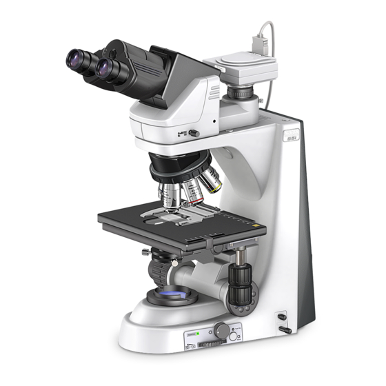
Page 16: Chapter 1 Part Names
Part Names Names of Main Components Eyepiece Eyepiece tube Revolving nosepiece Objective Microscope (main body) Specimen holder Stage Condenser... -
Page 17: Names Of Parts Used To Make Adjustments
Chapter 1 Part Names 1.2 Names of Parts Used to Make Adjustments Names of Parts Used to Make Adjustments Right view 1.2.1 Diopter adjustment ring Optical path switching lever Refocusing lever Aperture diaphragm knob Y stage knob X stage knob 50i: ND filter IN/OUT lever 55i:... -
Page 18: Left View
Chapter 1 Part Names 1.2 Names of Parts Used to Make Adjustments Left view 1.2.2 Condenser focus knob Coarse focus torque adjustment knob Coarse focus knob Fine focus knob Condenser centering screws Power switch... -
Page 19: Rear View (50I)
Chapter 1 Part Names 1.2 Names of Parts Used to Make Adjustments Rear view (50i) 1.2.3 Handle Wiring guides Wiring guides Input voltage indication Lamphouse AC inlet Tool 50i with lamphouse cover open Lamphouse cover Halogen lamp... -
Page 20: Rear View (55I)
Chapter 1 Part Names 1.2 Names of Parts Used to Make Adjustments Rear view (55i) 1.2.4 Handle Wire guides Wire guides Wiring cover Tool 55i with wiring cover open Connector J4 Connector J2 (for cytodiagnostic (for cytodiagnostic unit unit signal cable) power supply cable) Connector J3 Connector J1... -
Page 21: Ergonomic Binocular Tube With Camera Attached
Chapter 1 Part Names 1.2 Names of Parts Used to Make Adjustments Ergonomic binocular tube with camera attached 1.2.5 Camera cable connector Camera head C mount Camera fine focus adjustment ring Camera centering screws... -
Page 22: With Cytodiagnostic Unit Attached
Chapter 1 Part Names 1.2 Names of Parts Used to Make Adjustments With cytodiagnostic unit attached 1.2.6 Magnification indicator Object marker knob Hand switch Side and rear views of cytodiagnostic unit 50i: AC adapter able (thick) 55i: J-CY/PS Power supply cable (thick) Cytodiagnostic unit power switch 50i: Hand switch cable (thin) -
Page 23: With Fluorescence Attachment Mounted
Chapter 1 Part Names 1.2 Names of Parts Used to Make Adjustments With fluorescence attachment mounted 1.2.7 Optical path switching lever Mercury lamphouse Filter cube motion restricting lever Shutter Field diaphragm lever Light shielding plate Filter cube switching knob (Mercury lamps require a separate power source.) Filter cube replacement cover ND filter... -
Page 24: Chapter 2 Microscopy
Microscopy Bright-Field Microscopy The ECLIPSE 55i with the low magnification objective may result in uneven illumination in the field of view. (If the cytodiagnostic unit is mounted, refer to the directions in the following section entitled “2. Microscopy with Cytodiagnostic Unit Attached.”) Turn on power. - Page 25 Chapter 2 Microscopy 2.1 Bright-Field Microscopy Set the 10x objective into the optical path. Select the 10x objective. Set a specimen and move the portion to be viewed into the optical path. Set a specimen and secure in place using the ⇒...
-
Page 26: Interpupillary Distance
Chapter 2 Microscopy 2.1 Bright-Field Microscopy Adjust the diopter and the interpupillary distance. ⇒ ⇒ ⇒ ⇒ P.43 ⇒ ⇒ ⇒ ⇒ P.44 Focus and center the condenser. ⇒ ⇒ ⇒ ⇒ P.45 Focus the condenser Center the condenser using the condenser using the condenser focus knob. - Page 27 Chapter 2 Microscopy 2.1 Bright-Field Microscopy Turn off power after completing observation. Press the power switch to the “◯” position.
-
Page 28: Microscopy With Cytodiagnostic Unit Attached
Chapter 2 Microscopy 2.2 Microscopy with Cytodiagnostic Unit Attached Microscopy with Cytodiagnostic Unit Attached Turn on power. ⇒ ⇒ ⇒ ⇒ P.35 Press the switch to the “|” position. Insert the cytodiagnostic unit power switch. Raise the condenser to the uppermost position. - Page 29 Chapter 2 Microscopy 2.2 Microscopy with Cytodiagnostic Unit Attached Set a specimen and move the portion to be viewed into the optical path. Set a specimen and secure in place using the ⇒ ⇒ ⇒ ⇒ P.42 specimen holder. Move the portion to be viewed into the optical path using the XY stage knobs.
- Page 30 Chapter 2 Microscopy 2.2 Microscopy with Cytodiagnostic Unit Attached Switch magnification using the hand switch. Adjust the field diaphragm and aperture diaphragm for optimal image quality. ⇒ ⇒ ⇒ ⇒ P.50 ⇒ ⇒ ⇒ ⇒ P.46 ⇒ ⇒ ⇒ ⇒ P.47 Contrast may be reduced when viewing certain Aperture specimens at 40×...
-
Page 31: Microscopy With Fluorescence Attachment Mounted
Chapter 2 Microscopy 2.3 Microscopy with Fluorescence Attachment Mounted Microscopy with Fluorescence Attachment Mounted Before microscopy • Check the cumulative operating hours of the mercury lamp. Replace the lamp if its cumulative operating hours exceed the average service life. • Use non-fluorescent slide glass. •... - Page 32 Chapter 2 Microscopy 2.3 Microscopy with Fluorescence Attachment Mounted Fully open the field diaphragm of the fluorescence attachment. ⇒ ⇒ ⇒ ⇒ P.51 Fully open the field diaphragm. Turn on the mercury lamp, then open the shutter and center the lamp.
- Page 33 Chapter 2 Microscopy 2.3 Microscopy with Fluorescence Attachment Mounted Use the ND filter to adjust brightness. Switch to the desired objective and view the specimen. • Refocus. • Use the ND filter for the fluorescence attachment to adjust brightness. • Adjust the field diaphragm so that it extends slightly beyond the field of view.
-
Page 34: Photomicroscopy
Chapter 2 Microscopy 2.4 Photomicroscopy Photomicroscopy For detailed discussions of the camera, photomicroscopic software, and PC, refer to the operating manuals provided with the respective products. The following instructions assume a DS-5M digital camera and DS-L1 camera control unit. Adjust the microscope for proper image observation. See the directions given in sections from “1. - Page 35 Chapter 2 Microscopy 2.4 Photomicroscopy Select the camera scene mode suitable for the microscopy method. Set the camera white balance. To adjust white balance, press the WB button while capturing an image of a clear section of a specimen slide. (For fluorescent photomicrography, adjust white balance under normal lighting conditions before shooting.) Capture and save images.
-
Page 36: Chapter 3 Individual Operations
Individual Operations Item Title Operating sections Power ON/OFF Power switch, battery, AC adapter Brightness Adjustment Brightness control knob, preset switch, ND filter, color compensating filter Optical Path Switching Optical path switching knob Vertical Stage Motions Coarse/fine adjustment knobs, coarse torque adjustment ring, refocusing lever Lateral Stage Motions X knob, Y knob, XY knob torque adjustment screws... -
Page 37: Power On/Off
Chapter 3 Individual Operations 3.1 Power ON/OFF Power ON/OFF Turning on the microscope 3.1.1 To turn on the microscope, press the power switch to the “|” position. To turn off the microscope, press the power switch to the “◯” position. Power switch Turning on the cytodiagnostic unit 3.1.2... -
Page 38: Brightness Adjustment
Chapter 3 Individual Operations 3.2 Brightness Adjustment Brightness Adjustment Image brightness can be adjusted by the following methods: Method Operating controls Explanation Transmitted Adjusting lamp voltage Brightness control knob 3.2.1 image (The 50i is subject to shifts Preset switch 3.2.2 in color temperature.) Preset brightness control knob ND filter... -
Page 39: Adjustment Using The Preset Switch
Chapter 3 Individual Operations 3.2 Brightness Adjustment Adjustment using the preset switch 3.2.2 Push in the preset switch to enable the brightness level (lamp voltage) previously set with the preset brightness control knob. Toggle the preset switch – i.e., return it to the out position –... -
Page 40: Automatic Adjustment After Magnification Change (Only For A 55I When A Cytodiagnostic Unit Is Mounted)
Chapter 3 Individual Operations 3.2 Brightness Adjustment Automatic adjustment after magnification change 3.2.4 (only for a 55i when a cytodiagnostic unit is mounted) If the cytodiagnostic unit is mounted to a 55i, pressing the hand switch to change magnification will also activate brightness adjustment. However, the brightness control knob must not be at the maximum setting, and the preset switch must not be in the depressed position for this... -
Page 41: Camera Adjustment (Adjusting The Brightness Of The Image On The Monitor)
Chapter 3 Individual Operations 3.3 Optical Path Switching Camera adjustment 3.2.7 (adjusting the brightness of the image on the monitor) When observing images captured by the camera and displayed on the monitor, you can adjust brightness by varying camera adjustment parameters, such as display mode, exposure mode, metering mode, exposure compensation, and image level adjustment. -
Page 42: Vertical Stage Motion
Chapter 3 Individual Operations 3.4 Vertical Stage Motion Vertical Stage Motion Prohibited actions 3.4.1 Avoid the following actions, which can cause equipment malfunctions. Rotating the right and left coarse/fine focus knobs in opposite directions. • • Rotating the coarse focus knob past the stopper. Knob rotation direction and stage motion direction 3.4.2 Turn the coarse or fine focus knob to raise or lower... -
Page 43: Adjusting The Rotating Torque Of The Coarse Focus Knob
Chapter 3 Individual Operations 3.4 Vertical Stage Motion Adjusting the rotating torque of the coarse focus knob 3.4.4 Adjust the rotation torque of the coarse focus knob (rotation resistance) by turning the torque adjustment ring (TORQUE) located at the base of the coarse focus knob. -
Page 44: Lateral Stage Motion
Chapter 3 Individual Operations 3.5 Lateral Stage Motion Lateral Stage Motion Prohibited action 3.5.1 Avoid the following actions, which can cause equipment malfunctions. • Moving the stage to the left and right by holding the top surface of the stage directly. -
Page 45: Diopter Adjustment
Chapter 3 Individual Operations 3.6 Diopter Adjustment Diopter Adjustment Diopter adjustment compensates for differences in visual acuity between the right and left eyes, improving binocular observation. It also minimizes focal deviations when switching objectives. Adjust diopter settings for both eyepiece lenses. (1) Turn the diopter adjustment ring of each eyepiece lens and align the end face of the Line... -
Page 46: Interpupillary Adjustment
Chapter 3 Individual Operations 3.7 Interpupillary Adjustment Interpupillary Adjustment Interpupillary adjustment improves the ease of binocular observation. The right and left Perform steps 1) to 10) in “2-1. Bright-Field fields of view Microscopy” and focus on the specimen using the converge until they coincide. -
Page 47: Adjusting The Condenser Position
Chapter 3 Individual Operations 3.9 Adjusting the Condenser Position Adjusting the Condenser Position Adjust the condenser (focusing and centering) so that the light passing through the condenser forms an image at the correct location (center of the optical path) on the specimen surface. (1) Perform steps 1) to 10) in “2-1. -
Page 48: Adjusting The Aperture Diaphragm
70 to 80% of the maximum aperture of the objective will provide satisfactory images with Plan 40X suitable contrast. 40x / 0.75 Nikon JAPAN Plan 40x 40x / 0.75 / -WD / -WD Since an excessively small aperture diaphragm... -
Page 49: Selecting A Condenser
Chapter 3 Individual Operations 3.11 Selecting a Condenser Selecting a Condenser 3.11 Condenser ( : Optimum, : Suitable, x: Not suitable) Objective Achromatic/aplanat Swing-out Achromat Abbe Low-magnification 1-100x magnification condenser condenser condenser condenser condenser condenser Note 2 Note 3 Note 2 Note 1 10x to 100x Note 1:... -
Page 50: Oil Immersion Operation
Chapter 3 Individual Operations 3.13 Oil Immersion Operation Oil Immersion Operation 3.13 Objectives marked “Oil” are oil-immersion objectives. Objectives of this type are used with immersion oil applied between the specimen and the tip of the objective. For maximum performance, oil-immersion objectives with numerical apertures of 1.0 or higher should be combined with oil-immersion chromatic/aplanat condensers. -
Page 51: Water Immersion
Chapter 3 Individual Operations 3.14 Water Immersion Water Immersion 3.14 Objectives marked “WI” or “W” are water-immersion objectives. These objectives are used with immersion water (distilled water or physiological saline) applied between the specimen and the tip of the objective. Microscopy procedures are the same as for oil-immersion objectives. Since water evaporates readily, monitor the immersion water during observation. -
Page 52: Using The Cytodiagnostic Unit
Chapter 3 Individual Operations 3.15 Using the Cytodiagnostic Unit 3.15 Using the Cytodiagnostic Unit Installing a cytodiagnostic unit on the microscope allows users to switch magnification using the hand switch and to mark the specimen. Magnification switching 3.15.1 Pressing the hand switch toggles magnification between 10x and 40x. -
Page 53: Fluorescence Observation
Chapter 3 Individual Operations 3.16 Fluorescence Observation Fluorescence Observation 3.16 Warning 3.16.1 The mercury lamp (or xenon lamp) used with the fluorescence attachment requires careful handling. Be sure to read the warnings described in the beginning of this manual and in the operating manual provided by the manufacturers of the super high-pressure mercury light source (or high-intensity light source) and lamp. -
Page 54: Switching Excitation Methods
Chapter 3 Individual Operations 3.16 Fluorescence Observation Switching excitation methods 3.16.5 Four filter cubes can be mounted on the Filter cube switching knob fluorescence attachment. Move the desired cube into the optical path by turning the filter cube switching knob on the right side of the device. For bright-light observations, leave one cube Filter motion position empty, and move this empty position into... -
Page 55: Nd Filters For Fluorescence Attachment
Chapter 3 Individual Operations 3.16 Fluorescence Observation ND filters for fluorescence attachment 3.16.7 Push in the ND filter attach/detach lever to move ND filters into the optical path and darken the fluorescent image. ND filters are used to adjust light intensity. Higher filter numbers correspond to lower transmission rates (i.e., darker images). -
Page 56: Selecting Fluorescent Filters
Chapter 3 Individual Operations 3.17 Selecting Fluorescent Filters Selecting Fluorescent Filters 3.17 A filter cube is comprised of the following three optical components: an excitation filter (EX filter), a barrier filter (BA filter), and a dichroic mirror (DM). Select a combination of filter cubes appropriate for the specimen characteristics, Barrier filter fluorescent pigment, and the purpose intended. -
Page 57: Selecting Excitation Filters (Ex Filters)
Chapter 3 Individual Operations 3.17 Selecting Fluorescent Filters Selecting excitation filters (EX filters) 3.17.1 Excitation filters allow selective transmission of EX filter light (excitation light) in the waveband required for Bandwidth fluorescent light emissions from the specimen, blocking light of all other wavelengths. The range of wavelengths allowed to pass through a filter is referred to as bandwidth. - Page 58 Chapter 3 Individual Operations 3.17 Selecting Fluorescent Filters LP filter (long-pass filter) LP filters block all light below a certain wavelength LP520 but pass all light of longer wavelengths. This border wavelength is called a cut-on wavelength. Waveband emitted by Waveband (1) For specimens dyed with a fluorescent FITC...
-
Page 59: Replacing Excitation And Barrier Filters
Chapter 3 Individual Operations 3.17 Selecting Fluorescent Filters Replacing excitation and barrier filters 3.17.3 Excitation and barrier filters can be removed from Turn about 30° to secure in place. the fluorescent cube and replaced. (Dichroic mirrors cannot be dismounted from the fluorescent cube.) Excitation filters are screw-in filters. -
Page 60: Image Capture
Chapter 3 Individual Operations 3.18 Image Capture Image Capture 3.18 Images can be captured by mounting a camera head to the ergonomic binocular tube or trinocular eyepiece tube. For more detailed discussion of this topic, refer to the operating manual provided with the camera head or camera control software. -
Page 61: Making Adjustments To Keep Out Extraneous Light
Chapter 3 Individual Operations 3.18 Image Capture Making adjustments to keep out extraneous light 3.18.5 Field diaphragm: Stop down the diaphragm to a setting just slightly wider than the area shown on the monitor. Eyepiece: Cover the eyepiece with a cloth. Anti-vibration measures 3.18.6 If the exposure is less than 1/8 of a second, reduce light intensity with ND filters to make... -
Page 62: Chapter 4 Assembly
If the voltage indication and supply voltage differ, do not attempt to use the microscope. Contact your nearest Nikon representative to seek advice. Wiring at the Rear and Installing the Battery (for the 55i) (1) Confirm that the microscope is turned off. - Page 63 Chapter 4 Assembly Cables provided with the cytodiagnostic unit (1) J-CY/PS cable Cytodiagnostic unit connector 55i connector (2) J-CY/SG cable (both ends are identical) (4) Install a fully recharged battery (when using the 55i on battery power). Insert the battery into the battery holder. If the 55i is running on battery power, there is no need to connect the AC adapter to the J1 connector (12V DC input) at the rear of the 55i.
- Page 64 Chapter 4 Assembly (5) Replace the rear wiring cover. Engage the cover hook in the slot on the rear of the unit in the direction indicated by the arrow in the diagram. Lamp Lamphouse cover Slot for cover hook Lamphouse cover Cover hook CAUTION The rear wiring cover should always...
- Page 65 Chapter 4 Assembly Wiring of the Cytodiagnostic Unit Insert the cables into to the space exposed by the removed cover This procedure is required for the 55i. This procedure is optional for the 50i (performed when the two cables connecting to the cytodiagnostic unit need to be led out from the back of the microscope).
- Page 66 Chapter 4 Assembly Installing a Stage (1) Turn the coarse focus handle to remove the cushioning material from the substage section. (2) Turn the coarse focus handle until the elevating section is brought to the lowermost position. (3) Place the stage on the substage and fix into place with the tool stored in the back of the microscope.
- Page 67 Chapter 4 Assembly Installing a Fluorescent Attachment (when using a fluorescent attachment) (1) Place a fluorescent attachment on the microscope arm. (2) Secure in place with a clamp screw. (3) Fix the fluorescent attachment clamp bolt using the hex wrench provided with the unit. Clamp screws used to fix the fluorescent unit (4) Attach a mercury lamphouse to the bayonet...
- Page 68 Chapter 4 Assembly Notch Protrusion Installing an Eyepiece Make sure the notch on the eyepiece side and the protrusion of the eyepiece sleeve are aligned. Insert the eyepiece. When fitted correctly in place Installing a Revolving Nosepiece (or Cytodiagnostic Unit) 9-1 Installing a Revolving Nosepiece Revolving nosepiece fixing screw (1) Lift the revolving nosepiece from a position...
-
Page 69: Installing Objectives
Chapter 4 Assembly For the 50i: AC adapter cable (thick) (4) Check to confirm that the cytodiagnostic unit For the 55i: Power cable (thick) power switch is off. (5) Firmly insert two cables leading out from the bottom of the arm into the connectors on the back of the cytodiagnostic unit. - Page 70 Chapter 4 Assembly Installing Filter Cubes and Light Shield (with the fluorescence attachment installed) (1) Remove the cover on the front left of the fluorescence attachment. (2) Insert the filter cube. The filter cubes listed below cannot be installed directly into the fluorescence attachment filter bay.
- Page 71 Chapter 4 Assembly (6) Attach a light shield to the front bottom of the fluorescent attachment with the tool stored in the back of the microscope. Light shield Light shield fitted in place Installing a Camera (when using a camera) 12-1 When attaching to the ergonomic binocular tube: (1) To attach a camera head, screw it into the C Camera head...
- Page 72 Chapter 4 Assembly Installing the Power Cord 13-1 For the 50i: (1) Check to confirm that the microscope power switch is off. (2) Insert one end of the power cord into the AC inlet at the back of the microscope. (3) Insert the other end of the power cord into a wall outlet.
-
Page 73: Chapter 5 Replacing Consumables
Replacing Consumables Replacing the lamp (for the 50i) CAUTION • Be careful to avoid burns: Wait until the lamp and nearby parts have cooled before attempting to replace the lamp. • Be careful to avoid electrical shock: Turn off the power switch and unplug the power cord from the outlet. •... -
Page 74: Recharging The Battery (For The 55I)
Chapter 5 Replacing Consumables 5.2 Recharging the battery (for the 55i) Recharging the battery (for the 55i) CAUTION • When storing or carrying the battery removed from the microscope, be sure to attach the electrode cover (included with the battery). Shorting the battery terminals may result in various problems, including liquid leakage, heat generation, or explosion. -
Page 75: Refilling Cytodiagnostic Unit Ink
Chapter 5 Replacing Consumables 5.3 Refilling Cytodiagnostic Unit Ink Refilling Cytodiagnostic Unit Ink CAUTION • Use only the specified refill ink (J-CY refill ink). • Never attempt to disassemble the ink cartridge. • Avoid touching the exposed object marker while the ink cartridge is removed. -
Page 76: Chapter 6 Troubleshooting
Troubleshooting If the microscope does not function property, take appropriate action as described below. If the problem is still not resolved after referring to "Troubleshooting," please contact your nearest Nikon representative Optical Problem Possible causes Remedy Install the Parts (nosepiece, condenser, Parts installed incorrectly etc.) correctly. -
Page 77: Operational
Chapter 6 Troubleshooting 6.2 Operational Operational Problem Possible causes Remedy Image not in focus, although the objective Stage mounted incorrectly Mount correctly. is raised to the highest position Images in the left and Interpupillary adjustment not right eyepieces not Make adjustment. performed coincident Diopter adjustment not performed... -
Page 78: Chapter 7 Cleaning And Maintenance
Cleaning and Maintenance Lens cleaning Keep the lens free of dust, fingerprints, etc. Dirt on the lenses or filters will affect image quality. If any of the lenses become dirty, clean them by the procedure given below. Brush away dust with a soft brush or wipe away gently with gauze. •... -
Page 79: Storage
Periodic Inspections (fee charged) To maintain the peak performance of the microscope, we recommend periodic inspections. Contact your nearest Nikon representative for more information. (Parts and service charges apply for this service.) -
Page 80: Chapter 8 Specifications And Standards
Specifications and Standards Specifications Nikon Microscope ECLIPSE 50i Model ECLIPSE 50i Optical system Infinity-corrected CF optical system Objective: CF160 Objectives: Field number 22 (with ergonomic tube/binocular tube/cytodiagnostic unit), 25 (with trinocular eyepiece tube T/F) Nosepiece: Sextuple Focus up/down motion Drive system: Manual coarse/fine motion (calibration markings for fine motion: 1 µm/marking) - Page 81 Chapter 8 Specifications and Standards 8.1 Specifications Product safety • UL-listed product (UL61010A-1) • Meets FCC 15B Class A requirements. This equipment has been tested and found to comply with the limits for a Class A digital device, pursuant to Part 15 of the FCC Rules. These limits are designed to provide reasonable protection against harmful interference when the equipment is operated in a commercial environment.
- Page 82 Chapter 8 Specifications and Standards 8.1 Specifications Nikon Microscope ECLIPSE 55i Model ECLIPSE 55i Optical system Infinity-corrected CF optical system Objective: CF160 Objectives: Field number 22 (with ergonomic tube/binocular tube/cytodiagnostic unit), 25 (with trinocular eyepiece tube T/F) Nosepiece: Sextuple Focus up/down motion...
- Page 83 Chapter 8 Specifications and Standards 8.1 Specifications Transport/storage Temperature: -20 to 60°C conditions Humidity: 90% RH max. (no condensation) External dimensions and External dimensions: 184 (W) x 358 (H) x 383 (D) mm (excluding projections) weight (main unit) Weight: Approx. 8.5 kg Product safety •...
- Page 84 Chapter 8 Specifications and Standards 8.1 Specifications Nikon Microscopes J-FL 50i55i Epi-fluorescence Attachment Model J-FL 50i55i Epi-fluorescence Attachment Optical system Infinity-corrected CF optical system Variable intermediate magnification: 1X Fluorescent turret Manual quadruple turret Field diaphragm Manual (φ1 to 20 mm)
- Page 85 Chapter 8 Specifications and Standards 8.1 Specifications J-CY Cytodiagnostic Unit for Nikon Microscopes Model J-CY Cytodiagnostic Unit Optical system Infinity-corrected CF optical system Objective: Variable magnification lens: 2X, 0.5X Magnification Quick magnification adjustment by rotary solenoid adjustment system Operated by C-HS hand switch...
Need help?
Do you have a question about the Eclipse 50i and is the answer not in the manual?
Questions and answers