Sign In
Upload
Download
Table of Contents
Contents
Add to my manuals
Delete from my manuals
Share
URL of this page:
HTML Link:
Bookmark this page
Add
Manual will be automatically added to "My Manuals"
Print this page
×
Bookmark added
×
Added to my manuals
Manuals
Brands
Nikon Manuals
Microscope
ECLIPSE TE2000-E
Instructions manual
Nikon ECLIPSE TE2000-E Instructions Manual
Inverted microscope
Hide thumbs
1
2
3
4
5
6
Table Of Contents
7
8
9
10
11
12
13
14
15
16
17
18
19
20
21
22
23
24
25
26
27
28
29
30
31
32
33
34
35
36
37
38
39
40
41
42
43
44
45
46
47
48
49
50
51
52
53
54
55
56
57
58
59
60
61
62
63
64
65
66
67
68
69
70
71
72
73
74
page
of
74
Go
/
74
Contents
Table of Contents
Troubleshooting
Bookmarks
Table of Contents
Warning / Caution Symbols Used in this Manual
Meaning of Symbols Used on the Equipment
Notes on Handling the Microscope
Table of Contents
Parts of the Microscope and Their Names
Eyepiece Tubes and Eyepieces
Microscope Base
Dia-Illuminators
Condensers
Stages, Focusing Module
Microscope Rear
Power Supplies
II. Microscopy
Microscope System Consisting of TE2000-U, Dia-Illuminator 100W, System Condenser, and T-TD Eyepiece Tube D
Microscope System Consisting of TE2000-S, Dia-Illuminator 30W, SLWD Condenser, and T-TS Eyepiece Tube S
Microscope System Consisting of TE2000-E, Dia-Illuminator 30W
SLWD Condenser, and T-TS Eyepiece Tube S
Photomicrography (Using a 35-MM Camera Mounted on the Front Port)
Microscopy
Operation of each Part
Power ON/OFF
Brightness Adjustment
Optical Path Switching
Using Filters
Using Field Diaphragm
Using Condenser Aperture Diaphragm
Eyepiece Tube Turret
System Condenser
Objectives
Diopter Adjustment
Focusing Module
T-DH Dia-Illuminator 100W
T-SR Rectangular Stage
Photomicrography
IV. Assembly
Assembly
Eyepiece Tube
Power Supply
Troubleshooting
Care and Maintenance
VII. Technical Specifications
System Diagram
Technical Specifications
Advertisement
Quick Links
1
Parts of the Microscope and Their Names
2
Using Filters
Download this manual
M314E
04.7.CF.3(1/5)
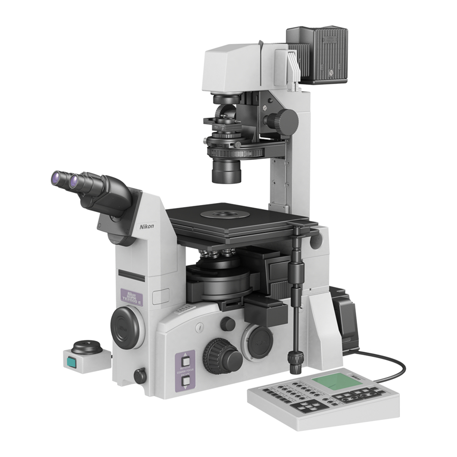
Inverted Microscope
ECLIPSE TE2000-E
ECLIPSE TE2000-U
ECLIPSE TE2000-S
Instructions
Table of
Contents
Previous
Page
Next
Page
1
2
3
4
5
Advertisement
Table of Contents
Need help?
Do you have a question about the ECLIPSE TE2000-E and is the answer not in the manual?
Ask a question
Questions and answers
Related Manuals for Nikon ECLIPSE TE2000-E
Microscope Nikon ECLIPSE TE2000-U Instructions Manual
Inverted microscope (74 pages)
Microscope Nikon ECLIPSE TE2000-S Instructions Manual
Inverted microscope (74 pages)
Microscope Nikon Eclipse TE300 Instructions Manual
(62 pages)
Microscope Nikon TE2000 Instructions Manual
Inverted microscope; colour image acquisition using nis-elements [basic research] software and the nikon digital sight ds-5m colour camera (8 pages)
Microscope Nikon TE2000 Manual
Fluorescent microscope (12 pages)
Microscope Nikon Eclipse TE200 Instructions Manual
Inverted microscope (55 pages)
Microscope Nikon eclipse Ti-U/B Instructions Manual
Inverted microscope (25 pages)
Microscope Nikon TSM Instructions Manual
Inverted (9 pages)
Microscope Nikon Eclipse TS100 Instructions Manual
(49 pages)
Microscope Nikon ECLIPSE TS100 Instructions Manual
Inverted microscope (55 pages)
Microscope Nikon ECLIPSE Ti2-U Instruction Manual
Inverted research microscope (203 pages)
Microscope Nikon Eclipse Ti TIFT 1454 Manual
Microscope (9 pages)
Microscope Nikon T1-FM Instructions Manual
Eclipse ts100/ts100-f epi-fluorescence attachment (61 pages)
Microscope Nikon Eclipse E600 Instructions Manual
(38 pages)
Microscope Nikon ECLIPSE 50i Instructions Manual
(86 pages)
Microscope Nikon eclipse E200 Instructions Manual
(88 pages)
This manual is also suitable for:
Eclipse te2000-u
Eclipse te2000-s
Table of Contents
Print
Rename the bookmark
Delete bookmark?
Delete from my manuals?
Login
Sign In
OR
Sign in with Facebook
Sign in with Google
Upload manual
Upload from disk
Upload from URL


Need help?
Do you have a question about the ECLIPSE TE2000-E and is the answer not in the manual?
Questions and answers