AMX NXA-ENET8-2POE Operation/Reference Manual
Gigabit ethernet layer 2 poe switch
Hide thumbs
Also See for NXA-ENET8-2POE:
- Instruction manual (165 pages) ,
- Installation manual (2 pages)

Related Manuals for AMX NXA-ENET8-2POE


Summary of Contents for AMX NXA-ENET8-2POE
- Page 1 O p e r a t i o n / R e f e r e n c e G u i d e NXA-ENET8-2POE Gigabit Ethernet Layer 2 PoE Switch M a n a g e d E t h e r n e t S w i t c h e s...
- Page 2 AMX is not responsible for products returned without a valid RMA number. AMX is not liable for any damages caused by its products or for the failure of its products to perform. This includes any lost profits, lost savings, incidental damages, or consequential damages.
-
Page 3: Table Of Contents
Rear Panel Components..................11 Power Supply Inlet ......................11 Grounding Point......................11 Web Console ......................12 Default Login Information..................12 Default IP Address ......................12 Default User Name and Password................. 12 Detailed Configuration Information ................12 NXA-ENET8-2POE Gigabit Ethernet Layer 2 PoE Switch... - Page 4 Cable Labeling and Connection Records ..............26 Cables and Pinouts ...................27 Twisted-Pair Cable Assignments ................27 Auto-Negotiation / MDI-X Support................. 27 10/100BASE-TX Pin Assignments .................. 27 10/100BASE-TX Pin Assignments ..................... 28 Straight-Through Wiring ......................28 NXA-ENET8-2POE Gigabit Ethernet Layer 2 PoE Switch...
- Page 5 Configuring Port Connections................. 47 Configuring Security ....................48 Configuring User Accounts.................... 48 Command Usage ........................49 Configuring User Privilege Levels ................. 50 Configuring The Authentication Method For Management Access....... 51 Usage Guidelines........................52 NXA-ENET8-2POE Gigabit Ethernet Layer 2 PoE Switch...
- Page 6 Configuring Global and Port Settings For ARP Inspection............82 Configuring Static Bindings For ARP Inspection ............... 83 Specifying Authentication Servers................. 84 Creating Trunk Groups ................... 85 Usage Guidelines......................85 Configuring Static Trunks ....................86 Usage Guidelines ........................86 NXA-ENET8-2POE Gigabit Ethernet Layer 2 PoE Switch...
- Page 7 Configuring VLAN Attributes For Port Members ............119 Configuring Private VLANs ................... 121 Using Port Isolation ....................121 Configuring MAC-based VLANs................122 Command Usage ......................122 Protocol VLANS ....................123 Command Usage ......................123 NXA-ENET8-2POE Gigabit Ethernet Layer 2 PoE Switch...
- Page 8 Displaying Information About Ports..............146 Displaying Port Status On the Front Panel ..............146 Displaying an Overview of Port Statistics..............146 Displaying QoS Statistics..................... 147 Displaying QCL Status ....................147 Displaying Detailed Port Statistics ................148 NXA-ENET8-2POE Gigabit Ethernet Layer 2 PoE Switch...
- Page 9 Showing IPV6 SSM Information................... 171 Displaying LLDP Information................. 172 Displaying LLDP Neighbor Information ............... 172 System Capabilities ........................ 172 Displaying LLDP-MED Neighbor Information .............. 173 Displaying LLDP Neighbor PoE Information..............174 Displaying LLDP Neighbor EEE Information..............175 NXA-ENET8-2POE Gigabit Ethernet Layer 2 PoE Switch...
- Page 10 Software Features ....................187 Management Features ..................188 Standards ......................188 Management Information Bases ................189 Appendix C: GNU License Information ............191 Overview ......................191 The GNU General Public License ................. 191 viii NXA-ENET8-2POE Gigabit Ethernet Layer 2 PoE Switch...
-
Page 11: Compliances And Safety Statements
• Power frequency magnetic field immunity (1 A/m at frequency 50 Hz) IEC 61000-4-8:2009 • Voltage dips, short interruptions and voltage variations immunity test according to IEC 61000-4-11:2004 (>95% Reduction @10 ms, 30% Reduction @500 ms, >95% Reduction @5000 ms) LVD: EN 60950-1: 2011 NXA-ENET8-2POE Gigabit Ethernet Layer 2 PoE Switch... -
Page 12: Power Cord Safety
The mains cord must comply with IEC 60227 (designation 60227 IEC 52). Europe The supply plug must comply with CEE7/7 (“SCHUKO”). The mains cord must comply with IEC 60227 (designation 60227 IEC 52). IEC-320 receptacle. NXA-ENET8-2POE Gigabit Ethernet Layer 2 PoE Switch... - Page 13 Dies muss von dem Land, in dem es benutzt wird geprüft werden Schweiz Dieser Stromstecker muß die SEV/ASE 1011Bestimmungen einhalten. Europe Das Netzkabel muss mit IEC 60227 (IEC 60227 entsprechen Bezeichnung 52) Der Netzstecker muß die Norm CEE 7/7 erfüllen (”SCHUKO”). NXA-ENET8-2POE Gigabit Ethernet Layer 2 PoE Switch...
-
Page 14: Warnings And Cautionary Messages
This product is manufactured in such a way as to allow for the recovery and disposal of all included electrical components once the product has reached the end of its life. Manufacturing Materials There are no hazardous nor ozone-depleting materials in this product. NXA-ENET8-2POE Gigabit Ethernet Layer 2 PoE Switch... -
Page 15: Nxa-Enet8-2Poe
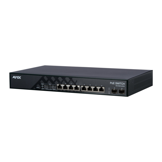
NXA-ENET8-2POE Overview The NXA-ENET8-2POE (FG2178-63) is a Gigabit Ethernet Layer 2 PoE switch with 8 10/100/1000BASE-T ports, and 2 Small Form Factor Pluggable (SFP) transceiver slots, (see FIG. 1, Ports 9-10). The NXA-ENET8-2POE also includes an SNMP-based management agent, which provides in-band access for managing the switch. -
Page 16: Network Interface
33 x 20.4 x 4.3 cm (12.99 x 8.03 x 1.69 in.) Weight 2.2 kg (4.85 lbs) Environmental Temperature: • Standard Operating: 0°C to 50°C (32°F to 122°F) • Non-Operating (Storage): -40°C to 70°C (-40°F to 158°F) Humidity 10% to 90% (non-condensing) NXA-ENET8-2POE Gigabit Ethernet Layer 2 PoE Switch... -
Page 17: Features
With a comprehensive array of LEDs, the NXA-ENET8-2POE provides “At-a-glance” monitoring of network and port status. The NXA-ENET8-2POE can be managed over the network via the Web Console. See the Using the Web Console section on page 31 for details. -
Page 18: Power-Over-Ethernet (Poe)
NXA-ENET8-2POE Power-Over-Ethernet (PoE) All eight ports (1~8) of the NXA-ENET8-2POE support the IEEE 802.3at standard that enables DC power to be supplied to attached devices using wires in the connecting Ethernet cable. The total PoE power delivered by all ports cannot exceed the 75 W power budget. -
Page 19: Front Panel Components
SFP Transceiver Slots Refer to the Fiber Optic SFP Devices section on page 23. The following table shows a list of transceiver types which have been tested with the NXA-ENET8-2POE. Supported SFP Transceivers Media Standard Fiber Diameter (microns) Wavelength (nm) -
Page 20: Port And System Status Leds
NXA-ENET8-2POE Port and System Status LEDs The NXA-ENET8-2POE includes a LED display panel on the front panel for key system and port indications that simplify installation and network troubleshooting (FIG. 4): Power Status LED PoE Status LEDs (ports 1 - 8) -
Page 21: Reset Button
To perform a reset using the existing configuration press the reset button for three seconds and release. Resetting to Defaults To reset the NXA-ENET8-2POE to its default configuration, by press and hold the reset button for more than ten seconds and release. -
Page 22: Web Console
NXA-ENET8-2POE Web Console The NXA-ENET8-2POE provides an embedded HTTP Web Console. Using a web browser you can configure the switch and view statistics to monitor network activity (FIG. 8). FIG. 8 Web Console (Home Page) The Web Console can be accessed by any computer on the network using a standard web browser (Internet Explorer 5.0, Netscape 6.2, Mozilla Firefox 2.0.0.0, or more recent versions). -
Page 23: Network Planning
Gigabit Ethernet ports built into the front panel, or a Gigabit Ethernet port on a plug-in SFP transceiver. In FIG. 9, the NXA-ENET8-2POE is operating as a collapsed backbone for a small LAN. It is providing dedicated 1000 Mbps full-duplex connections to workstations and 100 Mbps full-duplex connections to power users, and 1 Gbps full-duplex connections to servers. -
Page 24: Power Over Ethernet (Poe) Connections
The NXA-ENET8-2POE is an excellent choice for supplying power to connected PoE devices such as web cameras, IP telephones, or access points. In FIG. 10 the NXA-ENET8-2POE is supplying power to three PoE devices. It is also providing dedicated 1000 Mbps full-duplex data connections to these devices. In addition, other non-PoE devices can be connected to the switch. -
Page 25: Remote Connections With Fiber Cable
Remote Connections with Fiber Cable Making VLAN Connections The NXA-ENET8-2POE supports VLANs which can be used to organize any group of network nodes into separate broadcast domains. VLANs confine broadcast traffic to the originating group, and can eliminate broadcast storms in large networks. This provides a more secure and cleaner network environment. -
Page 26: Application Notes
Application Notes Full-duplex operation only applies to point-to-point access (such as when a NXA-ENET8-2POE is attached to a workstation, server, or another switch). When the NXA-ENET8-2POE is connected to a hub, both devices must operate in half-duplex mode. Avoid using flow control on a port connected to a hub unless it is actually required to solve a problem. -
Page 27: Installation
Ethernet Cabling To ensure proper operation when installing the NXA-ENET8-2POE into a network, make sure that the current cables are suitable for 10BASE-T, 100BASE-TX, or 1000BASE-T operation. Check the following criteria against the current installation of your network: ... -
Page 28: Optional Rack-Mounting Equipment
A screwdriver (Phillips or flathead, depending on the type of screws used). Mounting The NXA-ENET8-2POE can be mounted in a standard 19-inch equipment rack or on a desktop or shelf. Mounting instructions for each type of site follow. Rack Mounting Before rack mounting the NXA-ENET8-2POE, pay particular attention to the following factors: ... -
Page 29: Desktop Or Shelf Mounting
If installing a single switch only, turn to the Connecting To a Power Source section on page 19. If installing multiple switches, mount them in the rack, one below the other. Desktop or Shelf Mounting Attach the four adhesive feet to the bottom of the first NXA-ENET8-2POE (FIG. 18): FIG. 18 Attaching the Adhesive Feet Set the device on a flat surface near an AC power source, making sure there are at least two inches of space on all sides for proper air flow. -
Page 30: Installing An Optional Sfp Transceiver
However, always first disconnect the network cable before removing the transceiver. The NXA-ENET8-2POE uses lasers to transmit signals over fiber optic cable. The lasers are compliant with the requirements of a Class 1 Laser Product and are inherently eye safe in normal operation. -
Page 31: Network Connections
Network Connections Connecting Network Devices The NXA-ENET8-2POE is designed to be connected to 10, 100, or 1000 Mbps network cards in PCs and servers, as well as to other switches and hubs. It may also be connected to remote devices using optional 1000BASE-SX, 1000BASELX, 1000BASE-LH, or 100BASE-FX SFP transceivers. -
Page 32: Cabling Guidelines
Make sure each twisted pair cable does not exceed 100 meters (328 ft) in length. As each connection is made, the Link LED (on the NXA-ENET8-2POE) corresponding to each port will turn on (green or amber) to indicate that the connection is valid. -
Page 33: Network Wiring Connections
Network Wiring Connections Instructions for making connections in the wiring closet with this type of equipment follow: Attach one end of a patch cable to an available port on the NXA-ENET8-2POE, and the other end to the patch panel. If not already in place, attach one end of a cable segment to the back of the patch panel where the punch- down block is located, and the other end to a modular wall outlet. - Page 34 The 100BASE-FX fiber optic ports operate at 100 Mbps, full duplex, with auto-negotiation of flow control. The maximum length for fiber cable operating at 100 Mbps is listed in the 100 MBPS Fast Ethernet Collision Domain section on page 25. NXA-ENET8-2POE Gigabit Ethernet Layer 2 PoE Switch...
-
Page 35: Connectivity Rules
100 m (328 ft) RJ-45 10 MBPS Ethernet Collision Domain Maximum Ethernet Cable Length Type Cable Type Maximum Cable Length Connector 100BASE-T Category 3 or better 100-ohm UTP 100 m (328 ft) RJ-45 NXA-ENET8-2POE Gigabit Ethernet Layer 2 PoE Switch... -
Page 36: Cable Labeling And Connection Records
Use sequential numbers for cables that originate from the same equipment. Differentiate between racks by naming accordingly. Label each separate piece of equipment. Display a copy of your equipment map, including keys to all abbreviations at each equipment rack. NXA-ENET8-2POE Gigabit Ethernet Layer 2 PoE Switch... -
Page 37: Cables And Pinouts
Auto-negotiation MDI/MDIX means that every port on the switch will automatically detect the Ethernet cable type being used (straight-through or crossover) and adjust to make a link over that cable. The NXA-ENET8-2POE supports MDI-X on all ports. Therefore either cable type can be used. Follow TIA-568B straight-through cabling standards. -
Page 38: 10/100Base-Tx Pin Assignments
RJ-45 port on this switch, you can use either straight-through or crossover cable to connect to any device type.) You must connect all four wire pairs as shown in FIG. 25 to support Gigabit Ethernet connections: FIG. 25 Crossover Wiring NXA-ENET8-2POE Gigabit Ethernet Layer 2 PoE Switch... -
Page 39: 1000Base-T Pin Assignments
Replace any Category 5 patch cables with high-performance Category 5e or Category 6 cables. Reduce the number of connectors used in the link. Reconnect some of the connectors in the link. NXA-ENET8-2POE Gigabit Ethernet Layer 2 PoE Switch... -
Page 40: Fiber Standards
1600-nm region, with low loss in the 1550-nm band. G.655 Non-Zero Dispersion-Shifted Fiber Extended long-haul applications. Single-mode, 9/125-micron core Optimized for high-power dense wavelength-division multiplexing (DWDM) operation in the region from 1500 to 1600-nm. NXA-ENET8-2POE Gigabit Ethernet Layer 2 PoE Switch... -
Page 41: Using The Web Console
Using the Web Console Overview The NXA-ENET8-2POE provides a broad range of features for Layer 2 switching. These features can be configured via the NXA-ENET8-2POE’s embedded HTTP Web Console. While the default configuration can be used for most of the features provided by this switch, there are many options that you should configure to maximize the switch's performance for your particular network environment. -
Page 42: Configuration Options
Follow this procedure: Place the NXA-ENET8-2POE close to the PC that you intend to use for configuration. It helps if you can see the front panel of the switch while working on your PC. -
Page 43: Changing The Default Password
Refer to the following section (Configuring the NXA-ENET8-2POE on page 39) for details on using the Web Console to configure the NXA-ENET8-2POE. Refer to the Monitoring the NXA-ENET8-2POE section on page 143 for details on using the Web Console to monitor the NXA-ENET8-2POE. ... - Page 44 Port Mirroring The NXA-ENET8-2POE can unobtrusively mirror traffic from any port to a monitor port. You can then attach a protocol analyzer or RMON probe to this port to perform traffic analysis and verify connection integrity.
- Page 45 Up to 4K using IEEE 802.1Q, port-based, protocol-based, private VLANs, and voice VLANs, and QinQ tunnel. The NXA-ENET8-2POE supports up to 4096 VLANs. A Virtual LAN is a collection of network nodes that share the same collision domain regardless of their physical location or connection point in the network.
- Page 46 Queue mode and CoS configured by Ethernet type, VLAN ID, TCP/UDP port, DSCP, ToS bit, VLAN tag priority, or port. The NXA-ENET8-2POE prioritizes each packet based on the required level of ser- vice, using four priority queues with strict or Weighted Round Robin queuing. It uses IEEE 802.1p and 802.1Q tags to prioritize incoming traffic based on input from the...
-
Page 47: System Defaults
Enabled, RSTP (Defaults: RSTP standard) Spanning Tree Algorithm Edge Ports Enabled Address Table Aging Time 300 seconds Default VLAN PVID Virtual LANs Acceptable Frame Type All Ingress Filtering Disabled Switchport Mode (Egress Mode) Access NXA-ENET8-2POE Gigabit Ethernet Layer 2 PoE Switch... - Page 48 Proxy service: Disabled IGMP Snooping • Snooping: Disabled • Querier: Disabled Multicast Filtering MLD Snooping Disabled Multicast VLAN Registration Disabled Status Disabled System Log Messages Logged to Flash All levels Clock Synchronization Disabled NXA-ENET8-2POE Gigabit Ethernet Layer 2 PoE Switch...
-
Page 49: Configuring The Nxa-Enet8-2Poe
Click Configuration, System, Information. Specify the contact information for the system administrator, as well as the name and location of the switch. Also indicate the local time zone by configuring the appropriate offset. Click Save. NXA-ENET8-2POE Gigabit Ethernet Layer 2 PoE Switch... -
Page 50: Setting An Ip Address
Setting an IP Address This section describes how to configure an IP interface for management access to the switch over the network. The NXA-ENET8-2POE supports both IP Version 4 and Version 6, and can be managed simultaneously through either of these address types. -
Page 51: Setting An Ipv6 Address
An IPv6 default gateway must be defined if the management station is located in a different IPv6 segment. An IPv6 default gateway can only be successfully set when a network interface that directly connects to the gateway has been configured on the switch. NXA-ENET8-2POE Gigabit Ethernet Layer 2 PoE Switch... -
Page 52: Usage Guidelines
Maintaining an accurate time on the switch enables the system log to record meaningful dates and times for event entries. If the clock is not set, the switch will only record the time from the factory default set at the last bootup. FIG. 31 NTP Configuration NXA-ENET8-2POE Gigabit Ethernet Layer 2 PoE Switch... -
Page 53: Configuring Remote Log Messages
The syslog packet will always be sent out even if the syslog server does not exist. Click Configuration, System, Log. Enable remote logging, enter the IP address of the remote server, and specify the type of syslog messages to send. Click Apply. NXA-ENET8-2POE Gigabit Ethernet Layer 2 PoE Switch... -
Page 54: Configuring Power Reduction
Configuring the NXA-ENET8-2POE Configuring Power Reduction The NXA-ENET8-2POE provides power saving methods including controlling the intensity of LEDs, and powering down the circuitry for port queues when not in use. Controlling LED Intensity Use the LED Power Reduction Configuration page to reduces LED intensity during specified hours. -
Page 55: Reducing Power To Idle Queue Circuits
Click Configuration, Power Reduction, EEE. Select the circuits which will use EEE. If required, also specify urgent queues which will be powered up once data is queued and the default wakeup time has passed. Click Save. NXA-ENET8-2POE Gigabit Ethernet Layer 2 PoE Switch... -
Page 56: Configuring Thermal Protection
Click Configuration, Thermal Protection. Select the circuits which will use EEE. Set the temperature threshold for each priority, and then assign a priority level to each of the ports. Click Save. NXA-ENET8-2POE Gigabit Ethernet Layer 2 PoE Switch... -
Page 57: Configuring Port Connections
Avoid using flow control on a port connected to a hub unless it is actually required to solve a problem. Otherwise back pressure jamming signals may degrade over- all performance for the segment attached to the hub. NXA-ENET8-2POE Gigabit Ethernet Layer 2 PoE Switch... -
Page 58: Configuring Security
ARP traffic with invalid MAC to IP address bindings, which forms the basis for “man-in-the middle” attacks. Configuring User Accounts Use the User Configuration page to control management access to the switch based on manually configured user names and passwords. FIG. 37 User Configuration NXA-ENET8-2POE Gigabit Ethernet Layer 2 PoE Switch... -
Page 59: Command Usage
Generally, the privilege level 15 can be used for an administrator account, privilege level 10 for a standard user account, and privilege level 5 for a guest account. Click Configuration, System, Switch, Users Click Add new user. Enter the user name, password, and privilege level. Click Save. NXA-ENET8-2POE Gigabit Ethernet Layer 2 PoE Switch... -
Page 60: Configuring User Privilege Levels
Diagnostics: ping and VeriPHY. Maintenance: CLI - System Reboot, System Restore Default, System Password, Configuration Save, Configuration Load and Firmware Load. Web - Users, Privilege Levels and everything in Maintenance. Debug: Only present in CLI. NXA-ENET8-2POE Gigabit Ethernet Layer 2 PoE Switch... -
Page 61: Configuring The Authentication Method For Management Access
RADIUS-aware or TACACS-aware devices on the network. An authentication server contains a database of multiple user name/password pairs with associated privilege levels for each user that requires management access to the switch (FIG. 40). NXA-ENET8-2POE Gigabit Ethernet Layer 2 PoE Switch... -
Page 62: Usage Guidelines
Click Configuration, Security, Switch, Auth Method. Configure the authentication method for management client types, and specify whether or not to fallback to local authentication if no remote authentication server is available. Click Save. NXA-ENET8-2POE Gigabit Ethernet Layer 2 PoE Switch... -
Page 63: Configuring Ssh
HTTP web interface for the switch are automatically redirected to HTTPS. (Default: Disabled) Usage Guidelines If you enable HTTPS, you must indicate this in the URL that you specify in your browser: https://device[:port-number] NXA-ENET8-2POE Gigabit Ethernet Layer 2 PoE Switch... -
Page 64: Filtering Ip Addresses For Management Access
Click Configuration, Security, Switch, Access Management. Set the Mode to Enabled. Click Add new entry. Enter the start and end of an address range. Mark the protocols to restrict based on the specified address range. Click Save. NXA-ENET8-2POE Gigabit Ethernet Layer 2 PoE Switch... -
Page 65: Using Simple Network Management Protocol
Use the SNMP System Configuration page to configure basic settings and traps for SNMP. To manage the switch through SNMP, you must first enable the protocol and configure the basic access parameters. To issue trap messages, the trap function must also be enabled and the destination host specified. NXA-ENET8-2POE Gigabit Ethernet Layer 2 PoE Switch... - Page 66 A local engine ID is automatically generated that is unique to the switch. This is referred to as the default engine ID. If the local engine ID is deleted or changed, all local SNMP users will be cleared. You will need to reconfigure all existing users. NXA-ENET8-2POE Gigabit Ethernet Layer 2 PoE Switch...
- Page 67 Note: To select a name from this field, first enter an SNMPv3 user with the same Trap Security Engine ID in the SNMPv3 Users Configuration menu (see Configur- ing SNMPV3 Users section on page 58). Click Configuration, Security, Switch, SNMP, System. NXA-ENET8-2POE Gigabit Ethernet Layer 2 PoE Switch...
-
Page 68: Setting Snmpv3 Community Access Strings
Use the SNMPv3 User Configuration page to define a unique name and remote engine ID for each SNMPv3 user. Users must be configured with a specific security level, and the types of authentication and privacy protocols to use. FIG. 46 SNMPv3 User Configuration NXA-ENET8-2POE Gigabit Ethernet Layer 2 PoE Switch... -
Page 69: Configuring Snmpv3 Groups
SNMPv3 Access Configuration page (page 61). You can use the pre-defined default groups, or create a new group and the views authorized for that group. FIG. 47 SNMPv3 Group Configuration NXA-ENET8-2POE Gigabit Ethernet Layer 2 PoE Switch... -
Page 70: Configuring Snmpv3 Views
(Length: 1-128) Click Configuration, Security, Switch, SNMP, Views. Click Add new view to set up a new view. Enter the view name, view type, and OID subtree. Click Save. NXA-ENET8-2POE Gigabit Ethernet Layer 2 PoE Switch... -
Page 71: Configuring Snmpv3 Group Access Rights
MAC address and VLAN ID. If Limit Control is enabled on a port, the maximum number of users on the port is restricted to the specified limit. If this number is exceeded, the switch makes the specified response. FIG. 50 Port Limit Control Configuration NXA-ENET8-2POE Gigabit Ethernet Layer 2 PoE Switch... -
Page 72: System Configuration
Action is set to None or Trap. Shutdown: Indicates that the port is shut down by the Limit Control module. This state can only be shown if Action is set to Shutdown or Trap & Shutdown. NXA-ENET8-2POE Gigabit Ethernet Layer 2 PoE Switch... -
Page 73: Configuring Authentication Through Network Access Servers
The 802.1X standard defines a port-based access control procedure that prevents unauthorized access to a network by requiring users to first submit credentials for authentication. FIG. 51 Network Access Server Configuration NXA-ENET8-2POE Gigabit Ethernet Layer 2 PoE Switch... - Page 74 QoS Class information carried in the RADIUS Access- Accept packet transmitted by the RADIUS server when a supplicant is success- fully authenticated. If present and valid, traffic received on the supplicant’s port will be classified to the given QoS Class. NXA-ENET8-2POE Gigabit Ethernet Layer 2 PoE Switch...
- Page 75 Note: For trouble-shooting VLAN assignments, use the Monitor > VLANs >VLAN Membership and VLAN Port pages. These pages show which modules have (tem- porarily) overridden the current Port VLAN configuration. See the Guest VLAN Operation section on page 70 for details. NXA-ENET8-2POE Gigabit Ethernet Layer 2 PoE Switch...
- Page 76 - to wake up any supplicants that might be on the port. The maximum number of supplicants that can be attached to a port can be limited using the Port Security Limit Control functionality. NXA-ENET8-2POE Gigabit Ethernet Layer 2 PoE Switch...
- Page 77 Unauthorized - The port is in Force Unauthorized mode, or a single-supplicant mode and the supplicant is not successfully authorized by the RADIUS server. X Auth/Y Unauth - The port is in a multi-supplicant mode. X clients are currently authorized and Y are unauthorized. NXA-ENET8-2POE Gigabit Ethernet Layer 2 PoE Switch...
- Page 78 RADIUS authentication must be enabled on the switch and the IP address of the RADIUS server specified. Backend RADIUS servers are configured on the Authentication Configuration page (page 84). 802.1X / MAC-based authentication must be enabled globally for the switch. NXA-ENET8-2POE Gigabit Ethernet Layer 2 PoE Switch...
-
Page 79: Usage Guidelines
Dynamic QoS assignment fails and the authentication result changes from success to failure when the following conditions occur: Illegal characters found in a profile value (for example, a non-digital character in an 802.1p profile value). NXA-ENET8-2POE Gigabit Ethernet Layer 2 PoE Switch... -
Page 80: Radius Attributes Used In Identifying A Vlan Id
When port status changes to down, all MAC addresses are cleared from the secure MAC address table. Static VLAN assignments are not restored. Click Configuration, Security, Network, NAS. Modify the required attributes. Click Save. NXA-ENET8-2POE Gigabit Ethernet Layer 2 PoE Switch... -
Page 81: Filtering Traffic With Access Control Lists
The NXA-ENET8-2POE tests ingress packets against the conditions in an ACL one by one. A packet will be accepted as soon as it matches a permit rule, or dropped as soon as it matches a deny rule. If no rules match, the frame is accepted. -
Page 82: Configuring Rate Limiters
Rules applied to a port take effect immediately, while those defined for a policy must be mapped to one or more ports using the ACL Ports Configuration menu (see the Configuring Authentication Through Network Access Servers section on page 63). NXA-ENET8-2POE Gigabit Ethernet Layer 2 PoE Switch... -
Page 83: Access Control List Configuration
Shows the number of frames which have matched any of the rules defined for this ACL. Note: Refer to the QCE Modification Buttons section on page 77 for a description of the buttons used to edit or move the ACL entry (ACE). NXA-ENET8-2POE Gigabit Ethernet Layer 2 PoE Switch... - Page 84 (THA) field settings. (Options: Any - any value is allowed, 0 - RARP frames where THA is not equal to the DMAC address, 1 - RARP frames where THA is equal to the DMAC address; Default: Any) NXA-ENET8-2POE Gigabit Ethernet Layer 2 PoE Switch...
- Page 85 (Options: Any - any value is allowed, 0 - TCP frames where the SYN field is set must not match this entry, 1 - TCP frames where the SYN field is set must match this entry; Default: Any) NXA-ENET8-2POE Gigabit Ethernet Layer 2 PoE Switch...
- Page 86 Mirror parameter on the ACE Configuration page. Then open the Mir- ror Configuration page, set the Port to mirror on field to the required destination port, and leave the Mode field Disabled. NXA-ENET8-2POE Gigabit Ethernet Layer 2 PoE Switch...
-
Page 87: Usage Guidelines
Frame Type and IP Protocol Type. Specify the relevant criteria to be matched for this rule, and set the actions to take when a rule is matched (such as Rate Limiter, Port Copy, Logging, and Shutdown). Click Save. NXA-ENET8-2POE Gigabit Ethernet Layer 2 PoE Switch... -
Page 88: Configuring Dhcp Snooping
If a DHCP DISCOVER, REQUEST or INFORM message is received from a client, the packet is forwarded. If the DHCP packet is not a recognizable type, it is dropped. NXA-ENET8-2POE Gigabit Ethernet Layer 2 PoE Switch... -
Page 89: Additional Considerations When The Switch Itself Is A Dhcp Client
DHCP also provides a mechanism for sending information about the switch and its DHCP clients to the DHCP server. Known as DHCP Option 82, it allows compatible DHCP servers to use the information when assigning IP addresses, or to set other services or policies for clients. NXA-ENET8-2POE Gigabit Ethernet Layer 2 PoE Switch... -
Page 90: Configuring Ip Source Guard
Multicast addresses cannot be used by IP Source Guard. When enabled, traffic is filtered based upon dynamic entries learned via DHCP snooping (see "Configuring DHCP Snooping"), or static addresses configured in the source guard binding table. NXA-ENET8-2POE Gigabit Ethernet Layer 2 PoE Switch... -
Page 91: Configuring Static Bindings For Ip Source Guard
IP source guard binding. Only unicast addresses are accepted for static bindings. Click Configuration, Security, Network, IP Source Guard, Static Table. Click Add new entry. Enter the required bindings for a given port. Click Save. NXA-ENET8-2POE Gigabit Ethernet Layer 2 PoE Switch... -
Page 92: Configuring Arp Inspection
Use the ARP Inspection Configuration page to enable ARP inspection globally for the switch and for any ports on which it is required. FIG. 60 ARP Inspection Configuration ARP Inspection Configuration parameters ARP Inspection Configuration • Mode Enables Dynamic ARP Inspection globally. (Default: Disabled) NXA-ENET8-2POE Gigabit Ethernet Layer 2 PoE Switch... -
Page 93: Configuring Static Bindings For Arp Inspection
ARP packets to any entries specified in the static ARP table. If no static entry matches the packets, then the DHCP snooping bindings database determines their validity. Click Configuration, Network, Security, ARP Inspection, Static Table. Click Add new entry. Enter the required bindings for a given port. Click Save. NXA-ENET8-2POE Gigabit Ethernet Layer 2 PoE Switch... -
Page 94: Specifying Authentication Servers
Encryption key used to authenticate logon access for the client. (Maximum length: 29 characters) To set an empty secret, use two quotes (" "). To use spaces in the secret, enquote the secret. Quotes in the secret are not allowed. NXA-ENET8-2POE Gigabit Ethernet Layer 2 PoE Switch... -
Page 95: Creating Trunk Groups
All the ports in a trunk have to be treated as a whole when moved from/to, added or deleted from a VLAN. STP, VLAN, and IGMP settings can only be made for the entire trunk. NXA-ENET8-2POE Gigabit Ethernet Layer 2 PoE Switch... -
Page 96: Configuring Static Trunks
To avoid creating a loop in the network, be sure you add a static trunk via the configuration interface before connecting the ports, and also disconnect the ports before removing a static trunk via the configuration interface. NXA-ENET8-2POE Gigabit Ethernet Layer 2 PoE Switch... -
Page 97: Configuring Lacp
To avoid creating a loop in the network, be sure you enable LACP before connecting the ports, and also disconnect the ports before disabling LACP. If the target switch has also enabled LACP on the connected ports, the trunk will be activated automatically. NXA-ENET8-2POE Gigabit Ethernet Layer 2 PoE Switch... -
Page 98: Configuring Loop Protection
The period for which a port will be disabled if a loop is detected and the response is set to shut down the port. (Range: 0-604,800 seconds where the maximum is 7 days, and zero means to keep a port disabled until the switch is restarted; Default: 180 seconds) NXA-ENET8-2POE Gigabit Ethernet Layer 2 PoE Switch... -
Page 99: Command Usage
(FIG. 66). FIG. 66 STP Root Ports and Designated Ports Once a stable network topology has been established, all bridges listen for Hello BPDUs (Bridge Protocol Data Units) transmitted from the Root Bridge. NXA-ENET8-2POE Gigabit Ethernet Layer 2 PoE Switch... -
Page 100: Rstp
STP or RSTP nodes in the global network (FIG. 68). FIG. 68 Common Internal Spanning Tree, Common Spanning Tree, Internal Spanning Tree MSTP connects all bridges and LAN segments with a single Common and Internal Spanning Tree (CIST). NXA-ENET8-2POE Gigabit Ethernet Layer 2 PoE Switch... -
Page 101: Configuring Global Settings For Sta
In addition, each port needs time to listen for conflicting information that would make it return to a discarding state; otherwise, temporary data loops might result. Minimum: The higher of 4 or [(Max. Message Age / 2) + 1] Maximum: 30 Default: 15 NXA-ENET8-2POE Gigabit Ethernet Layer 2 PoE Switch... -
Page 102: Command Usage
RSTP Mode - If RSTP is using 802.1D BPDUs on a port and receives an RSTP BPDU after the migration delay expires, RSTP restarts the migration delay timer and begins using RSTP BPDUs on that port. NXA-ENET8-2POE Gigabit Ethernet Layer 2 PoE Switch... -
Page 103: Configuring Multiple Spanning Trees
MSTI Configuration parameters Configuration Identification • Configuration The name for this MSTI. (Maximum length: 32 characters; Default: switch’s MAC Name2 address) • Configuration The revision for this MSTI. (Range: 0-65535; Default: 0) Revision2 NXA-ENET8-2POE Gigabit Ethernet Layer 2 PoE Switch... -
Page 104: Command Usage
Use the MSTI Priority Configuration page to configure the bridge priority for the CIST and any configured MSTI. Remember that RSTP looks upon each MST Instance as a single bridge node. FIG. 71 MSTI Priority Configuration NXA-ENET8-2POE Gigabit Ethernet Layer 2 PoE Switch... -
Page 105: Configuring Stp/Rstp/Cist Interfaces
BPDU transparency allows a port which is not participating in the spanning tree (such as an uplink port to the service provider’s network) to forward BPDU packets to other ports instead of discarding these packets or attempting to pro- cess them. NXA-ENET8-2POE Gigabit Ethernet Layer 2 PoE Switch... - Page 106 Edge status does not affect this setting. A port entering error-disabled state due to this setting is subject to the bridge Port Error Recovery setting as well (see "Configuring Global Settings for STA" on page 120). NXA-ENET8-2POE Gigabit Ethernet Layer 2 PoE Switch...
-
Page 107: Path Costs
Default STA Path Costs Port Type Link Type IEEE 802.1w-2001 Ethernet Half Duplex 2,000,000 Full Duplex 1,000,000 Trunk 500,000 Fast Ethernet Half Duplex 200,000 Full Duplex 100,000 Trunk 50,000 Gigabit Ethernet Full Duplex 10,000 Trunk 5,000 NXA-ENET8-2POE Gigabit Ethernet Layer 2 PoE Switch... -
Page 108: Configuring Msti Interfaces
You may use a different priority or path cost for ports of the same media type to indicate the preferred path. (References to “ports” in this section means interfaces, which includes both ports and trunks.) Click Configuration, Spanning Tree, MIST Ports. Modify the required attributes. Click Save. NXA-ENET8-2POE Gigabit Ethernet Layer 2 PoE Switch... -
Page 109: Multicast Vlan Registration
Multicast VLAN Registration (MVR) is a protocol that controls access to a single network-wide VLAN most commonly used for transmitting multicast traffic (such as television channels or video-on-demand) across a service provider’s network. Any multicast traffic entering an MVR VLAN is sent to all attached subscribers. NXA-ENET8-2POE Gigabit Ethernet Layer 2 PoE Switch... -
Page 110: General Configuration Guidelines For Mvr
IGMP-enabled device, most commonly a multicast router. In this way, the switch can discover the ports that want to join a multicast group, and set its filters accordingly. NXA-ENET8-2POE Gigabit Ethernet Layer 2 PoE Switch... -
Page 111: Configuring Global And Port-Related Settings For Igmp Snooping
If no router port is configured in the attached VLAN, and Unregistered IPMC Flooding is disabled, any subsequent multicast traffic not found in the table is dropped, otherwise it is flooded throughout the VLAN. NXA-ENET8-2POE Gigabit Ethernet Layer 2 PoE Switch... - Page 112 Fast Leave does not apply to a port if the switch has learned that a multicast router is attached to it. Fast Leave can improve bandwidth usage for a network which frequently experi- ences many IGMP host add and leave requests. NXA-ENET8-2POE Gigabit Ethernet Layer 2 PoE Switch...
-
Page 113: Configuring Vlan Settings For Igmp Snooping And Query
LAN for group members. It then propagates the service requests on to any upstream multicast switch/router to ensure that it will continue to receive the multicast service. This feature is not supported for IGMPv3 snoop- ing. NXA-ENET8-2POE Gigabit Ethernet Layer 2 PoE Switch... -
Page 114: Configuring Igmp Filtering
IP/TV service based on a specific subscription plan. The IGMP filtering feature fulfills this requirement by denying access to specified multicast services on a switch port. FIG. 78 IGMP Snooping Port Group Filtering Configuration NXA-ENET8-2POE Gigabit Ethernet Layer 2 PoE Switch... -
Page 115: Mld Snooping
If no router port is configured in the attached VLAN, and Unregistered IPMCv6 Flooding is disabled, any subsequent multicast traffic not found in the table is dropped, otherwise it is flooded throughout the VLAN. NXA-ENET8-2POE Gigabit Ethernet Layer 2 PoE Switch... - Page 116 MLD throttling sets a maximum number of multicast groups that a port can join at the same time. When the maximum number of groups is reached on a port, any new MLD listener reports will be dropped. NXA-ENET8-2POE Gigabit Ethernet Layer 2 PoE Switch...
-
Page 117: Configuring Vlan Settings For Mld Snooping And Query
If the QRV exceeds 7, the maxi- mum value of the QRV field, the robustness value is set to zero, meaning that this device will not advertise a QRV in any query messages it subsequently sends. NXA-ENET8-2POE Gigabit Ethernet Layer 2 PoE Switch... -
Page 118: Configuring Mld Filtering
MLD report is dropped. Click Configuration, IPMC, MLD Snooping, Port Group Filtering. Click Add New Filtering Group to display a new entry in the table. Select the port to which the filter will be applied. NXA-ENET8-2POE Gigabit Ethernet Layer 2 PoE Switch... -
Page 119: Link Layer Discovery Protocol
(Range: 1-10 seconds; Default: 2 seconds) When LLDP is re-initialized on a port, all information in the remote system’s LLDP MIB associated with this port is deleted. NXA-ENET8-2POE Gigabit Ethernet Layer 2 PoE Switch... - Page 120 Modify any of the timing parameters as required. Set the required mode for transmitting or receiving LLDP messages. Enable or disable decoding CDP frames. Specify the information to include in the TLV field of advertised messages. Click Save. NXA-ENET8-2POE Gigabit Ethernet Layer 2 PoE Switch...
-
Page 121: Configuring Lldpmed Tlvs
With Fast start repeat count it is possible to specify the number of times the fast start transmission is repeated. The recommended value is 4 times, giving that 4 LLDP frames with a 1 second interval will be transmitted, when a LLDP frame with new information is received. NXA-ENET8-2POE Gigabit Ethernet Layer 2 PoE Switch... - Page 122 Name - Name (residence and office occupant). (Example: Flemming Jahn) Zip code - Postal/zip code. (Example: 2791) Building - Building (structure). (Example: Low Library) Apartment - Unit (Apartment, suite). (Example: Apt 42) Floor - Floor. (Example: 4) NXA-ENET8-2POE Gigabit Ethernet Layer 2 PoE Switch...
- Page 123 This application type should not be advertised if all the same network policies apply as those advertised in the Voice application policy. NXA-ENET8-2POE Gigabit Ethernet Layer 2 PoE Switch...
- Page 124 Both LLDP and LLDP-MED information can be used by SNMP applications to simplify troubleshooting, enhance network management, and maintain an accurate network topology. Click Configuration, LLDP-MED. Modify any of the timing parameters as required. NXA-ENET8-2POE Gigabit Ethernet Layer 2 PoE Switch...
-
Page 125: Power Over Ethernet
Reserved Power - Ports are shut down when total reserved powered exceeds the amount of power that the power supply can deliver. In this mode the port power is not turned on if the PD requests more power than available from the power supply. NXA-ENET8-2POE Gigabit Ethernet Layer 2 PoE Switch... -
Page 126: Command Usage
Command Usage The NXA-ENET8-2POE can provide DC power to a wide range of connected devices, eliminating the need for an additional power source and cutting down on the amount of cables attached to each device. Once configured to supply power, an automatic detection process is initialized by the switch that is authenticated by a PoE signature from the connected device. -
Page 127: Configuring The Mac Address Table
When a static address is seen on another port, the address will be ignored and will not be written to the address table. • Port Members Port identifier. NXA-ENET8-2POE Gigabit Ethernet Layer 2 PoE Switch... -
Page 128: Ieee 802.1Q Vlans
VLAN as an untagged port. Use the VLAN Membership Configuration page to enable VLANs for this switch by assigning each port to the VLAN group(s) in which it will participate. FIG. 86 VLAN Membership Configuration NXA-ENET8-2POE Gigabit Ethernet Layer 2 PoE Switch... -
Page 129: Configuring Vlan Attributes For Port Members
The switch will pass these frames on to the VLAN indicated in the outer tag. It will not strip the outer tag, nor change any compo- nents of the tag other than the EtherType field. • Port Port identifier. NXA-ENET8-2POE Gigabit Ethernet Layer 2 PoE Switch... - Page 130 VLAN ID assigned to untagged frames received on the interface. (Range: 1-4095; Default: 1) The port must be a member of the same VLAN as the Port VLAN ID. Click Configuration, VLANs, Ports. Configure in the required settings for each interface. Click Save. NXA-ENET8-2POE Gigabit Ethernet Layer 2 PoE Switch...
-
Page 131: Configuring Private Vlans
Add or delete members of any existing PVLAN, or click Add New Private VLAN and mark the port members. Click Save. Using Port Isolation Use the Port Isolation Configuration page to prevent communications between customer ports within the same private VLAN. FIG. 89 Port Isolation Configuration NXA-ENET8-2POE Gigabit Ethernet Layer 2 PoE Switch... -
Page 132: Configuring Mac-Based Vlans
Enter an address in the MAC Address field. Enter an identifier in the VLAN field. Note that the specified VLAN need not already be configured. Specify the ports assigned to this VLAN. Click Save. NXA-ENET8-2POE Gigabit Ethernet Layer 2 PoE Switch... -
Page 133: Protocol Vlans
Group Name -The name assigned to the Protocol VLAN Group. This name must be a unique 16-character long string which consists of a combination of alphabetic characters (a-z or A-Z) or integers (0-9). NXA-ENET8-2POE Gigabit Ethernet Layer 2 PoE Switch... -
Page 134: Mapping Protocol Groups To Ports
Click Configuration, VCL, Protocol-based VLANs, Group to VLAN. Enter the identifier for a protocol group. Enter the corresponding VLAN to which the protocol traffic will be forwarded. Select the ports which will be assigned to this protocol VLAN. Click Save. NXA-ENET8-2POE Gigabit Ethernet Layer 2 PoE Switch... -
Page 135: Managing Voip Traffic
44), the MVR VLAN (see the Multicast VLAN Registration section on page 99), or the native VLAN assigned to any port (see the Configuring VLAN Attributes For Port Members section on page 119). NXA-ENET8-2POE Gigabit Ethernet Layer 2 PoE Switch... -
Page 136: Port Configuration
OUI or LLDP will restart auto detection process. Click Configuration, Voice VLAN, Configuration. Configure any required changes to the VoIP settings for the switch or for a specific port. Click Save. NXA-ENET8-2POE Gigabit Ethernet Layer 2 PoE Switch... -
Page 137: Configuring Telephony Oui
This switch provides four priority queues for each port. Data packets in a port's high-priority queue will be transmitted before those in the lower-priority queues. You can set the default priority for each interface, the queuing mode, and queue weights. NXA-ENET8-2POE Gigabit Ethernet Layer 2 PoE Switch... -
Page 138: Configuring Port Classification
Controls the mapping of classified (PCP, DEI) to DP level (drop precedence) values when Tag Classification is Enabled. (Range: 0-1; Default: 0) Click Configuration, QoS, Port Classification. Set any of the ingress port QoS classification parameters. Click Save. NXA-ENET8-2POE Gigabit Ethernet Layer 2 PoE Switch... -
Page 139: Configuring Tag Classification For Tagged Frames
QoS Egress Port Schedulers parameters Displaying QoS Egress Port Schedulers • Port Port identifier. • Mode Shows the scheduling mode for this port. • Weight Shows the weight of each egress queue used by the port. NXA-ENET8-2POE Gigabit Ethernet Layer 2 PoE Switch... - Page 140 Unit - Controls the unit of measure for the port shaper rate as kbps or Mbps. (Default: kbps) Click Configuration, QoS, Port Scheduler. Click on any enter under the Port field to configure the Port Scheduler and Shaper. NXA-ENET8-2POE Gigabit Ethernet Layer 2 PoE Switch...
-
Page 141: Configuring The Scheduler Mode, Egress Queue Mode, Queue Shaper, And Port Shaper Used By Egress Ports
Configuring QoS Egress Port Scheduler, Queue Scheduler and Port Shapers This configuration page can be access from the Port Scheduler or Port Shaper page. Refer to the description of these parameters in the Configuring Egress Port Scheduler section on page 129. NXA-ENET8-2POE Gigabit Ethernet Layer 2 PoE Switch... -
Page 142: Configuring Port Remarking Mode
PCP/DEI values, or mapped versions of QoS class and drop priority. FIG. 100 QoS Egress Port Tag Remarking Showing the QoS Egress Port Tag Remarking Mode Used For Each Port FIG. 101 Displaying Port Tag Remarking Mode NXA-ENET8-2POE Gigabit Ethernet Layer 2 PoE Switch... -
Page 143: Configuring The Tag Remarking Mode
Disable - No Ingress DSCP Classification is performed. DSCP=0 - Classify if incoming DSCP is 0. Selected - Classify only selected DSCP for which classification is enabled in DSCP Translation table (see page 135). All - Classify all DSCP. NXA-ENET8-2POE Gigabit Ethernet Layer 2 PoE Switch... -
Page 144: Configuring Dscp-Based Qos Ingress Classification
(Range: 0-1, where 1 is the higher drop priority; Default: 0) Click Configuration, QoS, DSCP-Based QoS. Specify whether the DSCP value is trusted, and set the corresponding QoS value and DP level used for ingress processing. Click Save. NXA-ENET8-2POE Gigabit Ethernet Layer 2 PoE Switch... -
Page 145: Configuring Dscp Translation
Set the required ingress translation and egress re-mapping parameters. Click Save. Configuring DSCP Classification Use the DSCP Classification page to map DSCP values to a QoS class and drop precedence level. FIG. 105 DSCP Classification NXA-ENET8-2POE Gigabit Ethernet Layer 2 PoE Switch... -
Page 146: Configuring Qos Control Lists
Indicates the type of frame to look for in incoming frames. Possible frame types are: Any, Ethernet, LLC, SNAP, IPv4, IPv6. • SMAC The OUI field of the source MAC address, i.e. the first three octets (bytes) of the MAC address. NXA-ENET8-2POE Gigabit Ethernet Layer 2 PoE Switch... - Page 147 In other words, if value of the OUI field is 00-00-00, then value of the PID will be etherType (0x0600-0xffff), and if value of the OUI is other than 00-00-00, then valid value of the PID will be any value from 0x0000 to 0xffff. NXA-ENET8-2POE Gigabit Ethernet Layer 2 PoE Switch...
-
Page 148: Qce Modification Buttons
Inserts a new ACE before the current row. Edits the ACE. Moves the ACE up the list. Moves the ACE down the list. Deletes the ACE. The lowest plus sign adds a new entry at the bottom of the list. NXA-ENET8-2POE Gigabit Ethernet Layer 2 PoE Switch... -
Page 149: Configuring Storm Control
Select the control rate as a function of 2n pps (i.e., a value with no suffix for the unit of measure) or a rate in Kpps (i.e., a value marked with the suffix K). Click Save. NXA-ENET8-2POE Gigabit Ethernet Layer 2 PoE Switch... -
Page 150: Configuring Port Mirroring
To do this, a control point sends a suitable control message to the control URL for the service (provided in the device description). NXA-ENET8-2POE Gigabit Ethernet Layer 2 PoE Switch... - Page 151 Using UPnP under Windows XP - To access or manage the switch with the aid of UPnP under Windows XP, open My Network Places in the Explore file manager. An entry for NXA-ENET8-2PoE will appear in the list of discovered devices.
- Page 152 Configuring the NXA-ENET8-2POE NXA-ENET8-2POE Gigabit Ethernet Layer 2 PoE Switch...
-
Page 153: Monitoring The Nxa-Enet8-2Poe
(see the Setting an IP Address section on page 40. • System Uptime Length of time the management agent has been up. Software • Software Version Version number of runtime code. • Software Date Release date of the switch software. NXA-ENET8-2POE Gigabit Ethernet Layer 2 PoE Switch... -
Page 154: Displaying Cpu Utilization
Specifies the type of log messages to display. Info - Informational messages only. Warning - Warning conditions. Error - Error conditions. All - All levels. • Start from ID The error ID from which to start the display. NXA-ENET8-2POE Gigabit Ethernet Layer 2 PoE Switch... -
Page 155: Displaying Log Details
Detailed System Log Information Displaying Thermal Protection Use the Thermal Protection Status page to show the thermal status for each port and the current chip temperature (click Monitor, Thermal Protection). FIG. 115 Thermal Protection Status NXA-ENET8-2POE Gigabit Ethernet Layer 2 PoE Switch... -
Page 156: Displaying Information About Ports
The number of frames received with errors and the number of incomplete Transmitted transmissions. • Drops Received/ The number of frames discarded due to ingress or egress congestion Transmitted • Filtered Received The number of received frames filtered by the forwarding process. NXA-ENET8-2POE Gigabit Ethernet Layer 2 PoE Switch... -
Page 157: Displaying Qos Statistics
Select the user type to display from the drop-down list at the top of the page. If any of the entries display a conflict, click Resolve Conflict to release the resource required by a QCE. Then click Refresh to verify that the conflict has been resolved. NXA-ENET8-2POE Gigabit Ethernet Layer 2 PoE Switch... -
Page 158: Displaying Detailed Port Statistics
All values displayed have been accumulated since the last system reboot, and are shown as counts per second. Statistics are refreshed every 60 seconds by default. FIG. 120 Detailed Port Statistics NXA-ENET8-2POE Gigabit Ethernet Layer 2 PoE Switch... - Page 159 Rx Filtered - The number of received frames filtered by the forwarding process. • Transmit Error Tx Drops - The number of frames dropped due to output buffer congestion. Counters Tx Late/Exc. Coll - The number of frames dropped due to late or excessive collisions. NXA-ENET8-2POE Gigabit Ethernet Layer 2 PoE Switch...
-
Page 160: Displaying Information About Security Settings
Use the Port Security Switch Status page to show information about MAC address learning for each port, including the software module requesting port security services, the service state, the current number of learned addresses, and the maximum number of secure addresses allowed. FIG. 122 Port Security Switch Status NXA-ENET8-2POE Gigabit Ethernet Layer 2 PoE Switch... -
Page 161: Displaying Information About Learned Mac Addresses
The VLAN ID seen on this port. • State Indicates whether the corresponding MAC address is blocked or forwarding. In the blocked state, it will not be allowed to transmit or receive traffic. NXA-ENET8-2POE Gigabit Ethernet Layer 2 PoE Switch... -
Page 162: Displaying Port Status For Authentication Services
(see page 63). If the port is moved to the Guest VLAN, (Guest) is appended to the VLAN ID. Refer to Guest VLAN Enabled for a description of this attribute (see page 63). NXA-ENET8-2POE Gigabit Ethernet Layer 2 PoE Switch... -
Page 163: Displaying Port Statistics For 802.1X Or Remote Authentication Service
• Start The number of EAPOL Start frames that have been received by the switch. • Logoff The number of valid EAPOL Logoff frames that have been received by the switch. NXA-ENET8-2POE Gigabit Ethernet Layer 2 PoE Switch... - Page 164 802.1X-based: The protocol version number carried in the most recently received EAPOL frame. MAC-based: Not applicable. • Identity 802.1X-based: The user name (supplicant identity) carried in the most recently received Response Identity EAPOL frame. MAC-based: Not applicable. NXA-ENET8-2POE Gigabit Ethernet Layer 2 PoE Switch...
-
Page 165: Displaying Acl Status
Indicates the ingress port to which the ACE applies. Possible values are: Any: The ACE will match any ingress port. Policy: The ACE will match ingress ports with a specific policy. Port: The ACE will match a specific ingress port. NXA-ENET8-2POE Gigabit Ethernet Layer 2 PoE Switch... -
Page 166: Displaying Statistics For Dhcp Snooping
The number of discover (option 53 with value 1) packets received and transmitted. • Rx/Tx Offer The number of offer (option 53 with value 2) packets received and transmitted. • Rx/Tx Request The number of request (option 53 with value 3) packets received and transmitted. NXA-ENET8-2POE Gigabit Ethernet Layer 2 PoE Switch... -
Page 167: Displaying Dhcp Relay Statistics
The number of packets with a Circuit ID option that did not match a known circuit Circuit ID • Receive Bad The number of packets with a Remote ID option that did not match a known Remote ID remote ID. NXA-ENET8-2POE Gigabit Ethernet Layer 2 PoE Switch... -
Page 168: Displaying Mac Address Bindings For Arp Packets
Each page shows up to 999 entries from the Dynamic IP Source Guard table, default being 20, selected through the “entries per page” input field. When first visited, the web page will show the first 20 entries from the beginning of the Dynamic IP Source Guard Table. NXA-ENET8-2POE Gigabit Ethernet Layer 2 PoE Switch... -
Page 169: Displaying Information On Authentication Servers
Use the RADIUS Details page (click Monitor, Authentication, RADIUS Details) to display statistics for configured authentication and accounting servers. The statistics map closely to those specified in RFC4668 - RADIUS Authentication Client MIB. NXA-ENET8-2POE Gigabit Ethernet Layer 2 PoE Switch... - Page 170 The number of RADIUS packets of unknown type that were received from this server on the authentication port. • Packets Dropped The number of RADIUS packets that were received from this server on the authentication port and dropped for some other reason. NXA-ENET8-2POE Gigabit Ethernet Layer 2 PoE Switch...
- Page 171 A retry to the same server is counted as a retransmit as well as a timeout. A send to a different server is counted as a Request as well as a timeout. NXA-ENET8-2POE Gigabit Ethernet Layer 2 PoE Switch...
-
Page 172: Displaying Information On Lacp
Shows the local ports that are a part of this LAG. Displaying LACP Port Status Use the LACP Port Status page (click Monitor, LACP, Port Status) to display information on the LACP groups active on each port. FIG. 134 LACP Port Status NXA-ENET8-2POE Gigabit Ethernet Layer 2 PoE Switch... -
Page 173: Displaying Lacp Port Statistics
• LACP Transmitted The number of LACP frames sent from each port. • LACP Received The number of LACP frames received at each port. • Discarded The number of unknown or illegal LACP frames that have been discarded at each port. NXA-ENET8-2POE Gigabit Ethernet Layer 2 PoE Switch... -
Page 174: Displaying Loop Protection Status
The path cost from the root port on this switch to the root device. For the root bridge this is zero. For all other bridges, it is the sum of the port path costs on the least cost path to the root bridge. NXA-ENET8-2POE Gigabit Ethernet Layer 2 PoE Switch... - Page 175 RSTP states. • Uptime The time since the bridge port was last initialized. To display an overview of all STP bridge instances, click Monitor, Spanning Tree, Bridge Status. FIG. 138 Bridge Status NXA-ENET8-2POE Gigabit Ethernet Layer 2 PoE Switch...
-
Page 176: Displaying Port Status For Sta
Forward Delay parameter without receiving contradictory information. Port address table is cleared, and the port begins learning addresses. Forwarding - Port forwards packets, and continues learning addresses. • Uptime The time since the bridge port was last initialized. NXA-ENET8-2POE Gigabit Ethernet Layer 2 PoE Switch... -
Page 177: Displaying Port Statistics For Sta
• V2 Reports The number of IGMP V2 reports received. Received • V3 Reports The number of IGMP V3 reports received. Received • V2 Leaves The number of IGMP V2 leaves received. Received NXA-ENET8-2POE Gigabit Ethernet Layer 2 PoE Switch... -
Page 178: Displaying Mvr Group Information
Use the IGMP Snooping Status page (click Monitor, IGMP Snooping, Status) to display IGMP querier status, snooping statistics for each VLAN carrying IGMP traffic, and the ports connected to an upstream multicast router/switch. FIG. 144 IGMP Snooping Status NXA-ENET8-2POE Gigabit Ethernet Layer 2 PoE Switch... -
Page 179: Showing Igmp Snooping Group Information
IGMP Snooping Group Information parameters • VLAN ID VLAN Identifier. • Groups The IP address for a specific multicast service. • Port Members The ports assigned to the listed VLAN which propagate a specific multicast ser- vice. NXA-ENET8-2POE Gigabit Ethernet Layer 2 PoE Switch... -
Page 180: Showing Ipv4 Ssm Information
• Querier Version MLD version used by the switch when serving as the MLD querier. • Host Version MLD version used when used by this switch when serving as a host in MLD proxy mode. NXA-ENET8-2POE Gigabit Ethernet Layer 2 PoE Switch... -
Page 181: Showing Mld Snooping Group Information
(allow or deny). FIG. 149 MLD SSM Information MLD SSM Information parameters • VLAN ID VLAN Identifier. • Group The IP address of a multicast group detected on this interface. • Port No Port identifier. NXA-ENET8-2POE Gigabit Ethernet Layer 2 PoE Switch... -
Page 182: Displaying Lldp Information
• WLAN Access Point IEEE 802.11 MIB • Router IETF RFC 1812 • Telephone IETF RFC 2011 • DOCSIS cable device IETF RFC 2669 and IETF RFC 2670 • Station only IETF RFC 2011 NXA-ENET8-2POE Gigabit Ethernet Layer 2 PoE Switch... -
Page 183: Displaying Lldp-Med Neighbor Information
Example product categories expected to adhere to this class include (but are not limited to) Voice / Media Gateways, Conference Bridges, Media Servers, and similar. Discovery services defined in this class include media-type specific network layer policy discovery. NXA-ENET8-2POE Gigabit Ethernet Layer 2 PoE Switch... -
Page 184: Displaying Lldp Neighbor Poe Information
The port on this switch which received the LLDP frame. • Power Type Shows whether the device is a Power Sourcing Entity (PSE) or Power Device (PD). If the Type is unknown it is represented as Reserved. NXA-ENET8-2POE Gigabit Ethernet Layer 2 PoE Switch... -
Page 185: Displaying Lldp Neighbor Eee Information
• Resolved Tx Tw The resolved Tx Tw for this link (not the link partner). The resolved value that is the actual tx wakeup time used for this link (based on EEE information exchanged via LLDP). NXA-ENET8-2POE Gigabit Ethernet Layer 2 PoE Switch... -
Page 186: Displaying Lldp Port Statistics
Each LLDP frame can contain multiple pieces of information, known as TLVs. If a TLV is malformed, it is counted and discarded. • TLVs The number of well-formed TLVs, but with an unknown type value. Unrecognized NXA-ENET8-2POE Gigabit Ethernet Layer 2 PoE Switch... -
Page 187: Displaying Poe Status
Displaying the MAC Address Table Use the MAC Address Table (click Monitor, MAC Address Table) to display dynamic and static address entries associated with the CPU and each port. FIG. 156 MAC Address Table NXA-ENET8-2POE Gigabit Ethernet Layer 2 PoE Switch... -
Page 188: Displaying Information About Vlans
• Port Members The ports assigned to this VLAN. To display VLAN members, click Monitor, VLANs, VLAN Membership. Select a software module from the drop-down list on the right side of the page. NXA-ENET8-2POE Gigabit Ethernet Layer 2 PoE Switch... -
Page 189: Vlan Port Status
Refer to the preceding section for a description of the software modules that use VLAN management services. To display VLAN port status, click Monitor, VLANs, VLAN Port. Select a software module from the drop-down list on the right side of the page. NXA-ENET8-2POE Gigabit Ethernet Layer 2 PoE Switch... -
Page 190: Displaying Information About Mac-Based Vlans
• Port Members The ports assigned to this VLAN. To display MAC-based VLAN membership settings, click Monitor, VCL, MAC-based VLAN. Select a software module from the drop-down list on the right side of the page. NXA-ENET8-2POE Gigabit Ethernet Layer 2 PoE Switch... -
Page 191: Performing Basic Diagnostics
The payload size of the ICMP packet. (Range: 8- 1400 bytes) To ping another device on the network: Click Diagnostics, Ping or Ping6. Enter the IP address of the target device. Specify the packet size. Click Start. NXA-ENET8-2POE Gigabit Ethernet Layer 2 PoE Switch... -
Page 192: Running Cable Diagnostics
Note that VeriPHY is only accurate for cables 7 - 140 meters long. Ports will be linked down while running VeriPHY. Therefore, running VeriPHY on a management port will cause the switch to stop responding until testing is completed. NXA-ENET8-2POE Gigabit Ethernet Layer 2 PoE Switch... -
Page 193: Performing System Maintenance
Factory Defaults Upgrading Firmware Use the Software Upload page to upgrade the switch’s system firmware by specifying a file provided by AMX. You can download firmware files for your switch from the Tech Support section of the AMX web site: FIG. -
Page 194: Managing Configuration Files
Use the Configuration Upload page to restore previously saved configuration settings to the switch from a file on your local management station. Click Maintenance, Configuration, Upload. Click the Browse button, and select the configuration file. Click the Upload button to restore the switch’s settings. FIG. 166 Configuration Upload NXA-ENET8-2POE Gigabit Ethernet Layer 2 PoE Switch... -
Page 195: Appendix A: Troubleshooting
If you are trying to connect to the switch via the IP address for a tagged VLAN group, your management station, and the ports connecting intermediate switches in the network, must be configured with the appropriate tag. NXA-ENET8-2POE Gigabit Ethernet Layer 2 PoE Switch... -
Page 196: Forgot Or Lost The Password
Repeat the sequence of commands or other actions that lead up to the error. Make a list of the commands or circumstances that led to the fault. Also make a list of any error messages displayed. Contact your distributor’s service engineer. NXA-ENET8-2POE Gigabit Ethernet Layer 2 PoE Switch... -
Page 197: Appendix B: Software Specifications
• DNS Client, Proxy • LLDP (Link Layer Discover Protocol) • RMON (Remote Monitoring, groups 1,2,3,9) • SMTP Email Alerts • SNMP (Simple Network Management Protocol) • SNTP (Simple Network Time Protocol) • UPnP NXA-ENET8-2POE Gigabit Ethernet Layer 2 PoE Switch... -
Page 198: Management Features
IPv4 IGMP (RFC 3228) NTP (RFC 1305) RADIUS+ (RFC 2618) RMON (RFC 2819 groups 1,2,3,9) SNMP (RFC 1157) SNMPv2c (RFC 2571) SNMPv3 (RFC DRAFT 3414, 3415) SNTP (RFC 2030) SSH (Version 2.0) TFTP (RFC 1350) NXA-ENET8-2POE Gigabit Ethernet Layer 2 PoE Switch... -
Page 199: Management Information Bases
SNMP User-Based SM MIB (RFC 3414) SNMP View Based ACM MIB (RFC 3415) SNMPv2 IP MIB (RFC 2011) TACACS+ Authentication Client MIB TCP MIB (RFC 2012) Trap (RFC 1215) UDP MIB (RFC 2013) NXA-ENET8-2POE Gigabit Ethernet Layer 2 PoE Switch... - Page 200 Appendix B: Software Specifications NXA-ENET8-2POE Gigabit Ethernet Layer 2 PoE Switch...
-
Page 201: Appendix C: Gnu License Information
Program). Whether that is true depends on what the Program does. You may copy and distribute verbatim copies of the Program's source code as you receive it, in any medium, provided that you conspicuously and appropriately publish on each copy an appropriate copyright NXA-ENET8-2POE Gigabit Ethernet Layer 2 PoE Switch... - Page 202 Program or its derivative works. These actions are prohibited by law if you do not accept this License. Therefore, by modifying or distributing the Program (or any work based on NXA-ENET8-2POE Gigabit Ethernet Layer 2 PoE Switch...
- Page 203 RENDERED INACCURATE OR LOSSES SUSTAINED BY YOU OR THIRD PARTIES OR A FAILURE OF THE PROGRAM TO OPERATE WITH ANY OTHER PROGRAMS), EVEN IF SUCH HOLDER OR OTHER PARTY HAS BEEN ADVISED OF THE POSSIBILITY OF SUCH DAMAGES. END OF TERMS AND CONDITIONS NXA-ENET8-2POE Gigabit Ethernet Layer 2 PoE Switch...
- Page 204 - Schedules and registration for any AMX University course - Travel and hotel information - Your individual certification requirements and progress 3000 RESEARCH DRIVE, RICHARDSON, TX 75082 USA • 800.222.0193 • 469.624.8000 • 469-624-7153 fax • 800.932.6993 technical support • www.amx.com...
Need help?
Do you have a question about the NXA-ENET8-2POE and is the answer not in the manual?
Questions and answers